Product Certification
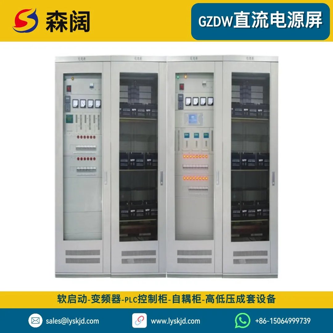
Senkuo GZDW Series High-Frequency Switching DC Power Supply Panel
System Voltage Level
Battery Capacity
Charger Capacity
Feeder Circuits
Purchase Quantity
Stock Remaining:100units

Professional Consultant for You

Product Overview
The GZDW series high-frequency switching DC power supply panel is a high-reliability DC power system designed specifically for substations, power plants, industrial and mining enterprises, and critical public facilities. It adopts advanced N+1 redundant high-frequency switching power supply technology and an intelligent monitoring management platform, providing continuous and stable DC power for control circuits, protection devices, signaling systems, emergency lighting, and circuit breaker operations. The system supports 220V/110V/48V multiple voltage levels, with capacity covering the full range from 20Ah to 3000Ah. It features automatic equalizing/floating charge conversion, online battery monitoring, insulation supervision, bus voltage anomaly alarm, and other functions. It complies with national standards including DL/T5044 Technical Code for Design of DC System in Power Engineering and GB/T19826 General Technical Conditions and Safety Requirements for DC Power Supply Equipment in Power Engineering, making it the ‘heart’ equipment ensuring safe grid operation.
N+1 Redundant Design
High-frequency switching power modules adopt N+1 hot-standby parallel operation. Single module failure automatically exits without affecting system output. Supports hot-swap replacement with MTBF >100,000 hours
Intelligent Three-Stage Charging
Fully automatic switching between main charge → equalizing charge → floating charge. Temperature-compensated charging voltage (-3mV/°C·cell) extends battery life by over 30%, effectively preventing overcharge and undercharge
Comprehensive Monitoring & Protection
Integrated AC input monitoring, module status supervision, battery inspection (individual cell voltage + temperature), bus insulation supervision (branch line selection), fault recording and SOE logs. 7-inch touchscreen real-time display, supports RS485/Ethernet remote communication
High Efficiency & Low Loss
High-frequency switching rectification efficiency ≥92%, power factor ≥0.95, total harmonic distortion THD <5%. Over 30% energy savings compared to traditional phase-controlled power supplies, significantly reducing operating costs and heat generation
Wide Range Adaptability
AC input voltage -15%~+10% (304V~456V AC), frequency 45Hz~65Hz, operating ambient temperature -10°C~+45°C, altitude ≤2000m without derating, suitable for various harsh conditions
Flexible Configuration & Expansion
Standard modular cabinet structure, freely combinable charging cabinet, feeder cabinet, and battery cabinet quantities. Reserved expansion interfaces support future smooth capacity upgrades or additional feeder circuits, protecting existing investment
Product Structure
The GZDW series DC power supply panel consists of three major functional units: charging cabinet, feeder cabinet, and battery cabinet. It adopts GGD standard cabinet dimensions (800mm×600mm×2260mm) or custom non-standard sizes, with overall layout following the 'top-in bottom-out' wiring principle. Core components include: (1) **High-frequency switching power modules** — converting three-phase AC380V to DC220V/110V/48V, each module independently controlled with multiple units in parallel current sharing; (2) **Monitoring unit** — ARM architecture industrial-grade controller responsible for data acquisition, logic judgment, HMI, and communication management; (3) **Silicon chain voltage regulator** — automatically adjusting the voltage difference between closing bus and control bus to ensure stable control bus voltage; (4) **Insulation supervision device** — real-time monitoring of DC system ground insulation resistance, automatic line selection and positioning upon ground fault; (5) **Battery patrol instrument** — detecting each battery terminal voltage and internal resistance (optional) to identify weak batteries early; (6) **Flash device** — providing pulse power required for circuit breaker position indicator lights; (7) **Voltage monitoring relay** — overvoltage/undervoltage alarm and trip output. The cabinet uses 2mm cold-rolled steel plate bent and welded, with epoxy resin powder spray anti-corrosion treatment. The front door has an observation window for viewing instrument readings and module status indicators. The top has a cooling air duct, and the bottom has cable entry/exit ports with sealing strips. Protection rating IP30/IP40 optional.
- **Charging Cabinet**: Houses N+1 high-frequency switching power modules (typically 10A/20A each), main monitoring unit, AC incoming switch, silicon chain voltage regulator, voltage monitoring relays, etc. Responsible for converting AC to DC and intelligent battery charging management
- **Feeder Cabinet**: Configured with DC circuit breakers (C-type/miniature MCBs), fuses, shunts, terminal blocks, etc. Divided into control feeders (powering protection/measurement devices) and closing feeders (powering circuit breaker spring charging motors/trip-close coils) on two bus sections. Each feeder circuit has status indicator lights and auxiliary contacts for telemetry acquisition
- **Battery Cabinet**: Houses valve-regulated sealed lead-acid batteries (VRLA) or lithium-ion battery packs. Depending on capacity, may occupy 1-4 cabinets. Equipped with battery inspection sensors (attached to each battery surface), temperature probes, ventilation fans (forced ventilation for large-capacity battery packs), and hydrogen detectors (lead-acid battery room safety monitoring)
- **Monitoring System**: Hardware level includes main monitoring board, LCD touchscreen (HMI), keypad operation panel, audible/visual alarm, RS485 communication expansion board, Ethernet interface, USB interface (for data export and firmware upgrade); Software level implements data acquisition and display, charging program control, fault diagnosis and alarm, historical data storage (up to 1 year), permission management (operator/engineer/administrator three-level passwords)
- **Auxiliary Accessories**: Including lightning protection modules (AC side B+C grade composite surge protection devices), isolation transformer (suppressing common-mode interference), EMI filter (purifying power quality), distributed power interface (DC-DC converter providing 48V for communication equipment), inverter power module (converting DC to AC 220V for UPS/computers and other critical loads)
GZDW Series DC Panel Model Numbering Rules and Technical Parameter Tables
Model Naming Example
GZDW - □ / □ - □ / □
 │      │   │    │    │
 │      │   │    │    └── Special identifier (optional)
 │      │   │    └─────── Feeder circuit count (e.g., 16 = control 8 + closing 8)
 │      │   └──────────── Battery capacity (Ah)
 │      └──────────────── System voltage (V)
 └──────────────────────── High-frequency switching DC power supply panel code
Example interpretation: GZDW-220/100-32 represents a DC power supply panel with 220V system, 100Ah battery capacity, 32 feeder circuits.
Standard Configuration Quick Reference (Common Specifications)
220V System Configuration List
| System Model | Battery Configuration | Charging Module Configuration | Cabinet Count | Feeder Circuits | Application Scenario |
|---|---|---|---|---|---|
| GZDW-220/20-8 | 20Ah × 54 cells (1 group) | 2×10A (1+1 redundant) | 2 (combined charging+feeder) | Control 4 + Closing 4 | Small distribution station/box substation |
| GZDW-220/40-12 | 40Ah × 54 cells (1 group) | 3×10A (2+1) | 2-3 | Control 6 + Closing 6 | 35kV substation/switching station |
| GZDW-220/65-16 | 65Ah × 54 cells (1 group) | 4×10A (3+1) | 3 | Control 8 + Closing 8 | 66kV substation/small hydropower |
| GZDW-220/100-24 | 100Ah × 54 cells (1 group) | 5×20A (4+1) | 4 | Control 12 + Closing 12 | 110kV substation/medium factory |
| GZDW-220/200-32 | 200Ah × 108 cells (2 groups parallel) | 8×20A (7+1) | 5-6 | Control 16 + Closing 16 | 220kV substation/large industrial |
| GZDW-220/300-40 | 300Ah × 108 cells (2 groups) | 10×20A (9+1) | 6-7 | Control 20 + Closing 20 | 500kV substation/hub station |
| GZDW-220/500-48 | 500Ah × 216 cells (4 groups parallel) | 14×20A (13+1) | 8-10 | Control 24 + Closing 24 | UHV station/large power plant |
110V System Configuration List (same feeder circuit count, battery quantity halved)
| System Model | Battery Configuration | Charging Module Configuration | Cabinet Count | Notes |
|---|---|---|---|---|
| GZDW-110/40-12 | 40Ah × 54 cells (1 group) | 4×10A (3+1) | 2-3 | Current doubles at same capacity, modules increase accordingly |
| GZDW-110/100-24 | 100Ah × 54 cells (1 group) | 8×10A (7+1) | 4 | Most common medium station configuration |
| GZDW-110/200-32 | 200Ah × 108 cells (2 groups) | 12×10A (11+1) | 5-6 | Suitable for applications with numerous critical loads |
48V System Configuration List (primarily for communication power)
| System Model | Battery Configuration | Charging Module Configuration | Cabinet Count | Application Field |
|---|---|---|---|---|
| GZDW-48/100-8 | 100Ah × 4 cells (1 group) | 2×20A (1+1) | 1-2 (embedded) | Communication base station/small exchange room |
| GZDW-48/200-12 | 200Ah × 24 cells (1 group) | 4×20A (3+1) | 2 | Medium data center/transmission node |
| GZDW-48/500-16 | 500Ah × 24 cells (1 group) | 8×20A (7+1) | 3 | Core equipment room/IDC DC power system |
Core Subsystem Details
I. High-Frequency Switching Power Module Technical Specifications
| Parameter | Technical Specification | Notes |
|---|---|---|
| Input voltage range | 304V~456V AC (three-phase four-wire) | Wide range input accommodates grid fluctuations |
| Input frequency range | 45Hz~65Hz | Compatible with generator power supply |
| Input power factor | ≥0.95 (rated load) | Active PFC correction, grid-friendly |
| Output voltage range | 198V 99V 43V~58V continuously adjustable (48V system) | Soft start ramp prevents inrush |
| Output voltage regulation accuracy | ≤±0.5% | From 0%~100% load step |
| Output current regulation accuracy | ≤±1% | In constant current charging mode |
| Output ripple | ≤200mV (peak-to-peak) | Near-pure DC after high-frequency filtering |
| Overall efficiency | ≥91% (full load) | Advanced soft-switching resonant technology |
| Operating temperature | -10°C ~ +45°C | Built-in intelligent temperature-controlled fan |
| Cooling method | Temperature-controlled forced air (quiet design) | Fan runs at low speed below 50% load for noise reduction |
| MTBF | >100,000 hours | Military-grade component screening |
| Dimensions/Weight | 86mm(W)×260mm(H)×135mm(D) / 3.5kg | 19-inch standard 3U height, hot-swappable |
| Current sharing imbalance | ≤±3% | Automatic current sharing in parallel modules |
| Dynamic response | <10ms (0-100% step) | Voltage transient dip <5% during load step |
| Soft start time | 3-8 seconds adjustable | Output voltage ramp-up on power-on |
II. Battery Selection Guide
Valve-Regulated Sealed Lead-Acid Battery (VRLA) Classification Comparison
| Type | Advantages | Disadvantages | Life (25°C) | Price Rating | Application Scenario |
|---|---|---|---|---|---|
| AGM (Absorbent Glass Mat) | Low internal resistance, good high-current discharge performance, moderate price | Not heat-resistant, prone to water loss, limited deep cycle life | 5-7 years | ★★★☆☆ | General purpose, best cost-effectiveness |
| Gel | Non-flowing electrolyte, heat-resistant (up to 45°C), long deep cycle life, no acid mist leakage | Poor low-temperature performance (capacity drops sharply below -10°C), higher price | 8-12 years | ★★★★☆ | High-temperature environments, outdoor cabinets, low-maintenance applications |
| OPzV (Tubular flooded) | Extremely long life, deep discharge resistant, heat-resistant, can be installed horizontally | Large volume, heavy weight, expensive, requires distilled water replenishment (maintenance type) | 15-20 years | ★★★★★ | Core power stations, critical power supply, harsh conditions |
| LiFePO₄ (Lithium iron phosphate) | Ultra-long cycle life (>2000 cycles), high energy density, fast charging, environmentally friendly (no heavy metals) | Highest cost (approximately 3-4 times lead-acid), requires BMS to prevent overcharge/overdischarge, limited low-temperature performance (60% capacity at -20°C) | 10-15 years (cycle life) | ★★☆☆☆ | Space/weight sensitive, frequent cycling, premium projects |
Selection recommendations:
- General indoor substations → AGM batteries (economical, 5-7 years with proper maintenance)
- Outdoor box substations/high-temperature workshops → Gel batteries (heat-resistant, low maintenance)
- 500kV and above hub stations/nuclear power plants → OPzV tubular batteries (ultra-high reliability)
- Mobile base stations/vehicle power/frequent outage areas → Lithium batteries (clear cycle life advantage)
III. Monitoring System Functional Architecture Diagram
┌─────────────────────────────────────────────────────────┐
│              Human-Machine Interface Layer (HMI)         │
│  ┌──────────────┐  ┌──────────────┐  ┌──────────────┐  │
│  │  7" Touchscr. │  │  Keypad Panel│  │ Audible/Visual│  │
│  │ (Graphical)  │  │  (Backup)    │  │    Alarm      │  │
│  └──────┬───────┘  └──────┬───────┘  └──────┬───────┘  │
│         └────────────────┼────────────────┘             │
│                          ▼                              │
│              ┌───────────────────────┐                  │
│              │  Main Monitoring Unit  │                  │
│              │  ARM Cortex-A7 1GHz   │                  │
│              │  Linux Embedded OS    │                  │
│              └───────┬───────┬───────┘                  │
│       ┌───────────────┼───────────────┐                 │
│       ▼               ▼               ▼                 │
│  ┌─────────┐   ┌───────────┐   ┌──────────┐           │
│  │  Data    │   │  Logic    │   │Communication│          │
│  │Acquisition│  │  Control  │   │ Management │          │
│  │ (ADC/DIO)│   │(Charging) │   │(Modbus/IEC)│          │
│  └────┬────┘   └─────┬─────┘   └─────┬────┘           │
│       │              │               │                  │
│  ┌────┴──────────────┴───────────────┴────┐            │
│  │         Slave/Intelligent Device Layer  │            │
│  │ ┌─────┐┌─────┐┌─────┐┌─────┐┌─────┐  │            │
│  │ │Power││Battery││Insul.││Feeder││Environ│  │            │
│  │ │Module││Patrol││Superv.││Monitor││Sensor│  │            │
│  │ └─────┘└─────┘└─────┘└─────┘└─────┘  │            │
│  └───────────────────────────────────────┘            │
└─────────────────────────────────────────────────────────┘
Installation, Commissioning and Acceptance Specifications
Pre-Installation Preparation
Civil Works Condition Confirmation
- Floor load-bearing capacity: Battery cabinet area ≥500kg/m² (large battery banks may reach 800-1000kg/m²)
- Room clear height: ≥2800mm (facilitating hoisting and heat dissipation)
- Door and window dimensions: Ensure cabinets can be smoothly moved in (standard cabinet 800mm wide × 600mm deep × 2260mm high)
- Ventilation facilities: Room air changes ≥3 times/hour, avoiding hydrogen accumulation
- Lighting: Illumination ≥300Lux, emergency lighting functioning normally
- Fire protection: Dry chemical or gas fire extinguishing systems, no sprinklers allowed
Electrical Condition Confirmation
- AC incoming cable: Selected per system capacity (typically 10-50mm² copper cable), length as short as possible to minimize voltage drop
- Grounding system: Independent grounding electrode, ground resistance <4Ω, cabinet reliably connected to grounding busbar (yellow-green wire cross-section ≥6mm²)
- Lightning protection: B+C grade composite surge protection device (SPD) on AC incoming side, grounding wire cross-section ≥6mm²
- Distribution protection: Incoming breaker with residual current protection (recommended 4P 63A-100A C-curve), coordinated upstream-downstream protection
Detailed Installation Steps
Step 1: Foundation Preparation and Cabinet Positioning
- Clear floor debris, mark cabinet arrangement positions (front/rear/left/right maintenance clearance ≥800mm reserved)
- Construct concrete foundation or channel steel base (height 100-150mm for cable entry/exit), leveling error <2mm/m
- Use forklift or hydraulic mover to position each functional cabinet sequentially (note nameplate orientation consistency, order: charging cabinet → feeder cabinet → battery cabinet)
- Adjust cabinet verticality with spirit level (deviation <1.5mm/m), adjacent cabinet joints flat and seamless
- Secure cabinets together with M10 galvanized bolts, weld entire assembly to foundation embedded steel or lock with anchor bolts
Step 2: Primary Wiring (Main Circuits)
- AC incoming: L1/L2/L3/N/PE respectively connected to charging cabinet bottom incoming terminals, correct phase sequence (confirm with phase sequence meter), torque per specification
- DC output: Charging cabinet positive/negative busbars respectively connected to feeder cabinet control bus and closing bus, using tinned copper busbars or large cross-section cables (≥50mm²), coated with power compound to prevent oxidation
- Battery connection: Strictly follow manufacturer’s ‘battery bank wiring diagram’ for series connection (note positive/negative polarity order! Reverse connection will damage equipment). Connection bar torque uniform between each battery (approximately 8-10N·M), end leads total positive/total negative to charging cabinet battery input switch
- Insulation testing: After all wiring completed, use 2500V megger (220V system) or 1000V megger (110V system) to measure main circuit ground insulation resistance, should be >10MΩ
Step 3: Secondary Wiring (Control Circuits)
- Per drawings, connect each feeder circuit’s auxiliary contacts (NO/NC), trip coils, closing coils, etc. one-to-one to feeder cabinet terminal blocks
- Insulation supervision device balancing resistors and detection bridge wiring per manual (incorrect wiring causes false alarms!)
- Battery patrol instrument voltage acquisition wires (2 per battery) and temperature sensors (attached near battery case negative terminal post) neatly bundled and secured
- RS485 communication wiring uses shielded twisted pair (recommended RVSP 2×0.5mm²), A/B polarity correct, shield single-point grounded
- All secondary wires marked with ferrules at both ends, wiring horizontal and vertical, bends with smooth arcs, securely fastened
Step 4: Pre-Energization Inspection
- Re-verify all wiring is correct (check off against schematic diagram one by one)
- Measure AC incoming voltage with multimeter (380V±10%)
- Open all outgoing breakers and battery switches, close AC incoming main breaker
- Check charging module fan rotation direction correct (blowing outward), no unusual odor/sound/smoke
- Measure charging module output voltage (should be within set range, default floating charge 243V for 220V system)
Step 5: System Commissioning and Parameter Setting
- Monitoring initialization: Power on and enter system setup menu, set date/time, language, password (change default password!), communication address (baud rate 9600, unique device address)
- Charging parameter setting: Float voltage (220V system typically 243V i.e., 2.25V/cell), equalizing voltage (245-247V i.e., 2.27-2.29V/cell), equalizing cycle (90 days), equalizing duration (10 hours), charging current limit (0.1C10), temperature compensation coefficient (-3mV/°C·cell)
- Alarm threshold setting: Bus overvoltage (229-246V adjustable, recommended 235V), bus undervoltage (198-210V adjustable, recommended 204V), battery overtemperature (40°C alarm, 45°C shutdown), insulation degradation (25kΩ alarm, 10kΩ trip)
- Insulation supervision calibration: Execute ‘auto calibration’ command during normal system operation (if available) to eliminate inherent ground capacitance effects
- Battery commissioning: Close battery switch, observe charging current is normal (should not exceed current limit), wait for transition to floating charge state (voltage stable, current gradually decreasing to very low)
Step 6: Trial Operation and Acceptance
- 24-hour trial operation: Observe all system parameters stable without abnormal fluctuations, maintain complete operation log
- Simulation tests: Simulate AC power loss (open incoming breaker) → battery should seamlessly take over power supply, bus voltage dip <5%; Simulate module failure (remove any one module) → remaining modules automatically share load with current balancing, voltage unchanged; Simulate insulation degradation (artificial grounding via adjustable resistor) → should accurately alarm and select line (if function available)
- Capacity test (optional): For important projects, a 30%-50% capacity verification discharge test is recommended (do not fully discharge to avoid damaging new batteries), verifying actual capacity meets specification
- Documentation handover: Provide complete as-built drawings (schematic, wiring, layout), product certificates, factory test reports, type test reports, operation and maintenance manuals, warranty cards, etc.
Ordering Guide and After-Sales Service
Standard Supply Scope (Per System)
| No. | Equipment/Material Name | Specification/Model | Qty | Unit | Notes |
|---|---|---|---|---|---|
| 1 | High-frequency switching power module | 10A/20A/30A (per configuration) | N+1 | pcs | Including cooling fan, current sharing cable |
| 2 | Main monitoring unit | ARM architecture + 7-inch touchscreen | 1 | set | Including software license, permanently free |
| 3 | Charging cabinet body | 800×600×2260mm GGD | 1-2 | pcs | IP30/IP40 optional |
| 4 | Feeder cabinet body | 800×600×2260mm GGD | 1-3 | pcs | Including DC breakers/fuses |
| 5 | Battery cabinet body | 800×600×2260mm GGD | 1-4 | pcs | Including battery rack/brackets/insulation mats |
| 6 | VRLA lead-acid batteries | 2V/12V (per capacity) | 1-4 groups | group | Manufacturer selectable (Shuangdeng/Shengyang/Nandu/Lishen, etc.) |
| 7 | Silicon chain voltage regulator | Auto/manual integrated | 1 | set | 20A-100A per system capacity |
| 8 | Insulation supervision device | Balanced bridge + branch line selection (optional) | 1 | pcs | Microcomputer type or simple type |
| 9 | Battery patrol instrument | Individual cell voltage + temperature detection | 1 | pcs | Supports up to 120 cells |
| 10 | Voltage monitoring relay | Overvoltage/undervoltage/voltage loss | 1-2 | pcs | Auxiliary contact output for telemetry |
| 11 | Flash device | Pulse generator | 1 | pcs | For circuit breaker position indication |
| 12 | AC incoming breaker | 3P/4P 63A-100A | 1 | pcs | With residual current protection preferred |
| 13 | Shunt | 75mV/XXA (per current) | 1-2 | pcs | For total current measurement |
| 14 | Lightning protection module | B+C grade composite SPD | 1-2 | pcs | 1 each on AC and DC sides |
| 15 | Connection cables/busbars | Per actual requirement | 1 | lot | Including terminals, ferrules |
| 16 | Random accessories | Spare parts kit | 1 | set | Fuses, fans, common screws, etc. |
| 17 | Technical documentation | Drawings/certificates/manuals | 1 | set | Hard copy + electronic (USB drive) |
Optional Value-Added Services
| Service Item | Description | Pricing | Recommendation |
|---|---|---|---|
| On-site installation guidance | Dispatch 1-2 senior engineers to site for installation supervision, wiring guidance, parameter commissioning, and operator training (1-2 days) | ¥3,000-5,000/person/day | ⭐⭐⭐⭐⭐ (Strongly recommended for first collaboration) |
| Battery installation service | Professional team handles battery placement, connection, tightening, and labeling (physically demanding + technical work for large battery banks) | ¥500-1,000/Ah | ⭐⭐⭐⭐ (Saves effort and worry) |
| Integration commissioning service | Assist connecting DC panel to substation automation system or upper-level dispatch master station, completing point verification and transmission testing | ¥5,000-10,000/station | ⭐⭐⭐⭐ (Essential for unattended operation) |
| Annual maintenance contract | Includes quarterly inspections (cleaning/dusting, tightening connections, battery testing), annual verification discharge test, emergency fault 4-hour on-site response | 3%-5% of equipment price/year | ⭐⭐⭐⭐⭐ (Ensures long-term stability) |
| Battery recycling & replacement | Environmentally compliant disposal of old batteries (per national hazardous waste regulations) + discounted new battery supply | Partial cost offset | ⭐⭐⭐⭐ (Regulatory compliance) |
| Remote O&M platform | Cloud monitoring SaaS service, mobile APP anytime access, intelligent alarm push, monthly health report | ¥2,000-5,000/year/station | ⭐⭐⭐⭐ (Improves management level) |
| Extended warranty | Extend from original 1-year warranty to 3 or 5 years (including parts and labor) | 2%-4% of equipment price/year | ⭐⭐⭐⭐ (Recommended for critical projects) |
Delivery Terms and Payment Conditions
| Item | Terms |
|---|---|
| Standard delivery time | Standard configuration 15-25 working days; Custom configuration (special cabinet dimensions, special voltage, imported batteries, etc.) 30-45 working days |
| Packaging & transport | Wooden crate + pearl cotton cushioning + vacuum aluminum foil bag moisture protection, domestic land/sea shipping available, freight collect (negotiable for special cases) |
| Payment terms | 30% advance payment upon contract signing → 60% progress payment before shipment → 5% upon commissioning acceptance → 5% retention after warranty period (1 year) |
| Quality guarantee | 18-month free warranty for complete system (from acceptance date), 3-year separate battery warranty (per manufacturer warranty certificate) |
| Training arrangements | Free 1-day on-site training (including system principle explanation, operation demonstration, simple troubleshooting); additional days at ¥1,500/person/day |
| Technical support hotline | 7×24-hour phone support: 400-XXX-XXXX; Working hours (8:00-18:00) online remote assistance; Major faults on-site arrival within 48 hours (major domestic cities) |
Synergistic Applications with Other Products
The GZDW DC panel can be combined with other company products to form complete power automation solutions:
- High/Low Voltage Distribution Systems: Can be combined with GGD low-voltage distribution cabinets, GCK low-voltage drawer cabinets, GCS AC low-voltage withdrawable switchgear, etc. to form a complete power supply and distribution system, with the DC panel providing control and protection power
- Motor Starting and Speed Control: Can work with online soft start cabinets, high-voltage solid-state soft starters, SK600 inverters, etc., with the DC panel powering their control circuits
- Compact Drive Solutions: When space is limited, can be paired with backpack inverters for integrated solutions
- Other Power Equipment: Can complement XL21 power distribution boxes, autotransformer reduced-voltage starting cabinets, etc.
Related Products
You may also like these products
 New
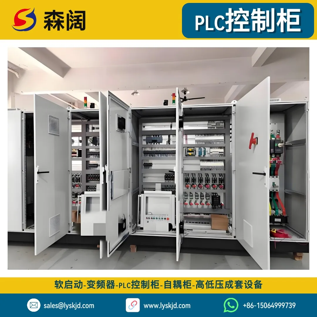
NewOMNIMECH Series PLC Control Cabinet - Industrial Automation Control System
The PLC control cabinet is an industrial automation control device centered on the Programmable Logic Controller (PLC), integrating electrical control, signal acquisition, logic operations, and communication networking. It collects on-site sensor signals and precisely controls actuators according to preset programs. It is widely used in production lines, water treatment, HVAC, power monitoring and other automation scenarios, and is a key core device for realizing intelligent and unmanned industrial production.
 New
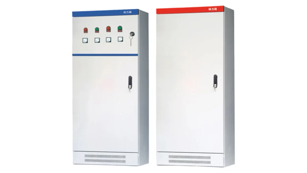
NewXL-21 AC Low Voltage Power Distribution Cabinet
XL-21 AC low voltage power distribution cabinet is suitable for power users such as power plants, substations, and industrial and mining enterprises with AC 50Hz, rated working voltage 380V, and rated working current up to 4000A. It is used for energy conversion, distribution, and control of power, lighting, and distribution equipment. The product features high breaking capacity, good dynamic and thermal stability, flexible electrical schemes, convenient combination, strong practicality, novel structure, and high protection level. It can be used as an update and replacement product for low voltage switchgear assemblies. XL-21 AC low voltage power distribution cabinet complies with IEC439 'Low-voltage Switchgear and Control Equipment', GB7251 'Low-voltage Switchgear Equipment' and other standards.
 New
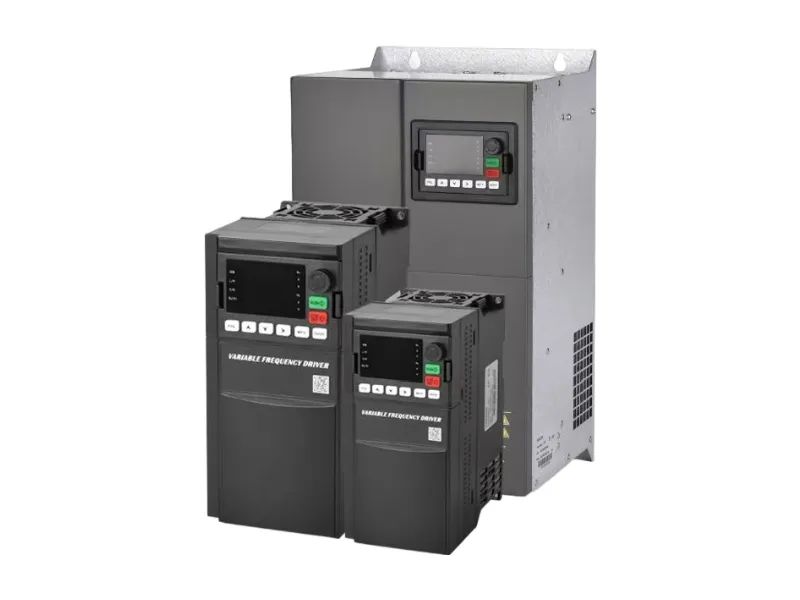
NewSenkuo SK800 Series High-Performance Low-Voltage Frequency Inverter - Vector Control Universal Inverter
The Senkuo SK800 series low-voltage frequency inverter is a high-performance vector control device designed for industrial automation, supporting both asynchronous motors and permanent magnet synchronous motors. It is suitable for various scenarios such as textiles, paper making, machine tools, fans, and pumps. Adopting advanced SVC algorithm and user-programmable functions, it provides stable and reliable driving performance.
 Hot
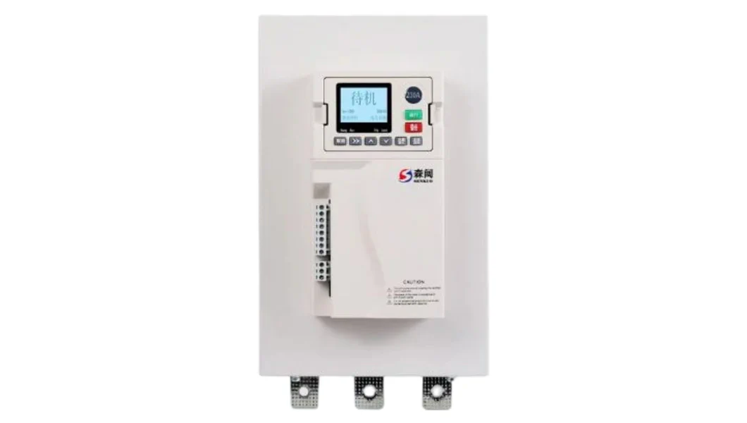
HotSenkuo SKR6800 Series Smart Online Soft Starter
The online soft starter produced by our company is a motor starting control device integrating advanced technology and reliable performance. Designed specifically for modern industrial production and various motor drive scenarios, it effectively reduces the impact on power grid and mechanical equipment during starting by smoothly controlling the motor starting current, providing a safe, stable and efficient starting solution for motors. Whether it is motor applications in industrial manufacturing, construction engineering, or commercial facilities, this soft starter can play a key role, improving equipment operation stability and extending equipment service life.
Need Customized DC System Solutions?
Our DC power technical team has extensive project experience in substations and power plants, providing professional system design, equipment selection, on-site commissioning, and lifetime technical support based on your specific requirements