# Linyi OmniMech Co., Ltd. / 临沂森阔机电有限公司 — Full Content
> Linyi OmniMech Co., Ltd. focuses on R&D and sales of high and low voltage complete sets of equipment and industrial automation products, providing complete industrial control solutions including power distribution equipment, PLC, servo systems, etc.
> 临沂森阔机电有限公司专注于高低压成套设备及工业自动化产品研发与销售,提供配电设备、PLC、伺服系统等全套工业控制解决方案。
This file contains the full text of the site's core pages, following the https://llmstxt.org specification.
中文版本(https://www.lyskjd.com/)内容与本文件一一对应,此处以英文正文为准。
---
# Careers
源地址: https://www.lyskjd.com/en/jobs/
摘要: Join us to grow together and realize your value
## About Us
Linyi OmniMech Co., Ltd. focuses on R&D and sales of high and low voltage complete sets of equipment and industrial automation products, providing complete industrial control solutions including power distribution equipment, PLC, servo systems, etc. We adhere to the business philosophy of "Integrity, Innovation, Win-Win", and are committed to providing customers with high-quality products and professional services.
## Recruitment Philosophy
Talent is the core driving force for enterprise development. We are committed to attracting and cultivating outstanding professional talents, providing employees with good development space and training opportunities, and growing together with the enterprise.
## Working Environment
- Modern office environment
- Harmonious team atmosphere
- Competitive salary and benefits
- Perfect training system
- Broad promotion space
## Contact Information
- Contact Phone:
- Recruitment Email:
- Company Address:
---
# Case Studies
源地址: https://www.lyskjd.com/en/cases/
摘要: Showcase our successful cases in different industries, including customer needs, solutions, and project results
## Our Successful Case Studies
Explore our successful projects across various industries, demonstrating how we provide tailored solutions to meet customer needs and deliver exceptional results.
## Industries We Serve
- **Manufacturing** - Industrial automation and power distribution solutions
- **New Energy** - Solar power generation and energy management systems
- **Smart Buildings** - Intelligent power distribution and building automation
- **Commercial Facilities** - Reliable power supply and energy efficiency solutions
- **Infrastructure** - Critical power systems for infrastructure projects
Each case study highlights our commitment to quality, innovation, and customer satisfaction.
---
# Download Center
源地址: https://www.lyskjd.com/en/downloads/
摘要: Provide company product manuals, technical documents, software tools and other resource downloads
## Welcome to Download Center
Here you can find product manuals, technical documents, software tools and other resources from Linyi OmniMech Co., Ltd. You can select the corresponding resources according to your needs for download.
## Resource Categories
- **Product Manuals** - Detailed product parameters and usage instructions
- **Technical Documents** - Technical white papers, industry solutions, case studies
- **Software Tools** - Device configuration software, debugging tools, monitoring software
- **Installation Drawings** - CAD drawings, installation guides, wiring diagrams
## Download Instructions
1. Click on the resource name to view detailed information
2. Click the "Download Now" button to start downloading
3. If you encounter download problems, please contact our technical support team
4. All resources are for reference only, please refer to the actual product
## Contact Information
- Phone:
- Email:
- Address:
---
# Help Center
源地址: https://www.lyskjd.com/en/docs/
摘要: Provide the latest product help, technical support, and customer service for the company
## Welcome to Help Center
Here you can find the latest product help, technical support, and customer service resources from Linyi OmniMech Co., Ltd. We are committed to providing you with comprehensive support to ensure your smooth use of our products.
## Support Resources
- **Product Manuals** - Detailed usage instructions and parameter specifications
- **Technical FAQs** - Answers to common technical questions
- **Troubleshooting Guides** - Solutions to common problems
- **Video Tutorials** - Step-by-step operation videos
- **Download Center** - Software tools and firmware updates
## Contact Support
If you need further assistance, please contact our technical support team:
- **Phone**:
- **Email**:
- **Working Hours**: ,
Our professional technical team will provide you with timely and effective support.
---
# Industrial Electrical Tools Center - Online Selection Calculators & Technical Tools
源地址: https://www.lyskjd.com/en/tools/
摘要: Professional industrial electrical tools center offering various online selection calculators and technical tools, including soft starter selection, VFD selection, cable selection, circuit breaker selection, helping engineers and technicians quickly complete electrical equipment selection and technical calculations.
## About Us
Linyi OmniMech Co., Ltd. focuses on R&D and sales of high and low voltage complete sets of equipment and industrial automation products, providing complete industrial control solutions including power distribution equipment, PLC, servo systems, etc. We adhere to the business philosophy of "Integrity, Innovation, Win-Win", and are committed to providing customers with high-quality products and professional services.
## Contact Information
- Contact Phone:
- Recruitment Email:
- Company Address:
---
# 2026 In-Depth Guide to Constant Pressure Water Supply VFD Control Cabinet Brands
源地址: https://www.lyskjd.com/en/articles/6/
摘要: China's constant pressure water supply VFD market size is expected to reach 16.83 billion RMB in 2025, with an annual growth rate of 10.5%. This growth is mainly driven by the promotion of the national 'dual carbon' goals and the acceleration of smart water utility construction, leading to continuous release of demand for industrial automation equipment. In the field of constant pressure water supply, VFD control cabinets as core equipment, their performance directly affects the stability, energy efficiency, and maintenance costs of water supply systems. This article will combine authoritative market data and expert opinions to recommend constant pressure water supply VFD control cabinet brands worth paying attention to in 2025.
## Key Points
- **Market Size**: According to the **Industrial Control Forum 2025 Annual Report**, the 2025 China [constant pressure water supply VFD]() market size is expected to reach 16.83 billion RMB, with an annual growth rate of 10.5%.
- **Competitive Landscape**: Foreign brands occupy 68% of the high-end market share, but domestic brands are accelerating substitution, with Inovance Technology maintaining the industry's first position for five consecutive years with a 24.7% market share in 2025.
- **Technology Trends**: **AI algorithms**, **edge computing**, and **digital twin technology** are reshaping the industry, with intelligent control cabinets supporting remote monitoring and predictive maintenance becoming mainstream.
- **Brand Recommendations**: Recommending 8 industry-leading brands including ABB, Siemens, Inovance Technology, and Invt, covering high, medium, and low-end market demands.
## Introduction
According to the **Industrial Control Forum 2025 Annual Report**, China's constant pressure water supply VFD market size is expected to reach 16.83 billion RMB in 2025, with an annual growth rate of 10.5%. This growth is mainly driven by the promotion of the national "dual carbon" goals and the acceleration of smart water utility construction, leading to continuous release of demand for industrial automation equipment. In the field of constant pressure water supply, [VFD control cabinets]() as core equipment, their performance directly affects the stability, energy efficiency, and maintenance costs of water supply systems. This article will combine authoritative market data and expert opinions to recommend constant pressure water supply VFD control cabinet brands worth paying attention to in 2025.
## Market Status and Competitive Landscape
### Overall Industry Development Trends
The "2024 Annual Industry Development Status" published by the **China Electrical Equipment Industry Association VFD Branch** shows that China's total installed motor capacity has reached over 400 million kW, with annual electricity consumption reaching 1.2 trillion kWh, accounting for 60% of the country's total electricity consumption and 80% of industrial electricity consumption. Motors using variable frequency speed regulation can save 15%-30% of energy, with huge energy-saving benefits. In the field of constant pressure water supply, variable frequency speed regulation technology has become mainstream, replacing traditional valve regulation methods, not only improving water supply quality but also significantly reducing energy consumption.
From the perspective of market competition landscape, foreign brands still occupy a dominant position in the high-end market. In 2024, foreign brands occupied 68% of the high-end market share, with major representative enterprises including ABB, Siemens, Danfoss, Schneider Electric, and Mitsubishi Electric. These international giants, with their long-term accumulation in core algorithms, IGBT module control, system integration capabilities, and global supply chain systems, maintain significant advantages in niche fields such as high-end industrial automation, rail transit, and new energy power generation that require extremely high reliability and precision.
However, domestic enterprises have achieved strategic extension from low-end and mid-end markets to high-end fields through continuous R&D investment and industrial chain collaboration in recent years. As a domestic leading enterprise, Inovance Technology achieved VFD business revenue of 6.87 billion RMB in 2023, a year-on-year increase of 19.4%, and for the first time surpassed Siemens with a 14.1% market share in the [general low-voltage VFD]() segment market, ranking first nationwide. Enterprises such as Invt, Xinfengguang, and Hikang New Energy are also performing actively, among which Invt has achieved domestic substitution breakthroughs in the rail transit traction VFD system field and has participated in multiple urban subway projects; Xinfengguang focuses on high-voltage VFDs, with market share steadily increasing in the power and cement industries, with high-voltage VFD shipments increasing by 26.8% year-on-year in 2023.

### Technology Development Trends
The "2024 China Low-Voltage VFD Market Research Report" by **Industrial Control Network** points out that current [constant pressure water supply VFD control cabinet]() technology development presents three major trends:
1. **Intelligence**: AI algorithms, edge computing, and digital twin technology are reshaping the industry. New-generation control cabinets are equipped with lightweight neural network models based on the TensorFlow Lite Micro framework, which can complete motor load status identification and abnormal vibration warning locally, with inference latency below 10 milliseconds and false alarm rate controlled within 0.8%.
2. **High Efficiency**: The application of wide-bandgap semiconductor materials (**SiC**/**GaN**) increases equipment efficiency to over 98.7% and reduces volume by 35%. **Tsinghua University Energy Internet Research Institute** calculations show that if the national stock of high-voltage motor systems is fully replaced with SiC-based VFD complete equipment, annual electricity savings can reach 38 billion kWh, equivalent to reducing carbon dioxide emissions by 31 million tons.

3. **Networking**: The application of industrial Ethernet protocols (PROFINET, EtherCAT, etc.) increases system data refresh rates to below 1ms, providing basic guarantees for high dynamic performance control. In 2024, the proportion of VFD cabinets using industrial Ethernet protocols exceeded 65%, effectively solving problems such as analog signals being susceptible to interference and limited transmission distance.
## Brand Recommendations and In-Depth Analysis
### High-End Market Brand Recommendations
#### 1. ABB
**Brand Introduction**: ABB is a global leading power and automation technology group, founded in 1988 and headquartered in Zurich, Switzerland. ABB's VFD products are world-renowned for their excellent performance, reliability, and innovative technology.
**Product Features**:
- **ACS880 Series**: Integrates Direct Torque Control (DTC) technology, still occupying an industry benchmark position in dynamic response and torque precision. This series of VFDs supports multiple control modes, including vector control, direct torque control, and V/F control, meeting the needs of different application scenarios.
- **High Reliability**: ABB VFDs use high-quality components and strict production processes to ensure stable operation of products even in harsh environments. The mean time between failures (MTBF) of the ACS880 series VFDs exceeds 50,000 hours.
- **Intelligent Functions**: Supports remote monitoring and predictive maintenance. Through the ABB Ability™ digital platform, users can monitor equipment operating status in real-time, discover potential faults in advance, and reduce downtime.
**Market Performance**: **International Energy Agency data** shows that ABB's application rate in China's water supply industry reaches 45%, and its latest AC800M series VFDs adopt AI algorithm-optimized control, capable of reducing energy consumption by over 20%.
#### 2. Siemens
**Brand Introduction**: Siemens is a global leading technology enterprise, founded in 1847 and headquartered in Munich, Germany. Siemens' automation products and solutions are widely used in industrial, energy, medical, and other fields.
**Product Features**:
- **Sinamics Series**: Relying on its TIA Totally Integrated Automation platform, it has significant advantages in system-level coordinated control. This series of VFDs supports multiple communication protocols, including PROFINET, PROFIBUS, and Modbus, enabling seamless integration with other devices.
- **Modular Design**: Adopts modular design philosophy, allowing users to flexibly configure VFD functions and performance according to needs. The power range of Sinamics series VFDs ranges from 0.12kW to 20MW, covering all application scenarios from small equipment to large industrial systems.
- **High Energy Efficiency**: Complies with IE5 ultra-high energy efficiency standards, capable of significantly reducing energy consumption. Siemens' VFD products fully consider energy-saving requirements in design, adopting advanced control algorithms and efficient power devices to ensure equipment always maintains optimal energy efficiency levels during operation.
**Market Performance**: Siemens maintains a leading position in high-reliability application scenarios such as process industry and rail transit, with VFD shipments in the China market increasing by approximately 6.8% year-on-year in 2024. Its MMF4 series occupies an important position in the smart building and municipal water supply fields, with a market share reaching 28%.
#### 3. Schneider Electric
**Brand Introduction**: Schneider Electric is a global leading energy management and automation solutions provider, founded in 1836 and headquartered in Rueil, France. Schneider Electric's products and solutions cover multiple fields including low-voltage power distribution, industrial automation, and building automation.
**Product Features**:
- **Altivar Series**: Adopts advanced vector control technology, capable of providing high-precision speed and torque control. This series of VFDs supports multiple motor types, including asynchronous motors, synchronous motors, and permanent magnet synchronous motors.
- **Integrated Solutions**: Provides complete solutions from VFDs to PLCs, HMIs, and sensors, achieving seamless integration of automation systems. Schneider Electric's EcoStruxure architecture can integrate IT data and OT data onto the same platform, providing excellent data collection, storage, and intelligent analysis services.
- **Eco-Friendly Design**: Complies with EU RoHS Directive and WEEE Directive requirements, using eco-friendly materials and processes to reduce environmental impact. Schneider Electric's VFD products fully consider sustainable development needs in design, committed to providing users with more eco-friendly and efficient solutions.
**Market Performance**: Schneider Electric's VFD sales in the China market are growing year by year, reaching 1.5 billion RMB in 2024, and expected to exceed 2 billion RMB by 2030. Its products are widely used in municipal water supply, wastewater treatment, and industrial automation fields.
### Mid-End Market Brand Recommendations
#### 4. Inovance Technology
**Brand Introduction**: Inovance Technology is a leading Chinese enterprise in the R&D, production, and sales of industrial automation control and new energy equipment core components, founded in 2003 and headquartered in Shenzhen. Inovance Technology's products cover multiple fields including VFDs, servo systems, PLCs, and HMIs.
**Product Features**:
- **MD800 Series**: Adopts the self-developed vector control platform IS620N, achieving high-cost-performance substitution in subdivided industries such as textiles, machine tools, and logistics. This series of VFDs supports AI edge computing, strengthening equipment predictive maintenance and remote operation and maintenance capabilities.
- **High Reliability**: Uses high-quality components and strict production processes to ensure stable operation of products even in harsh environments. Inovance Technology's VFD products have passed ISO9001 quality management system certification and CE certification, meeting international standard requirements.
- **Localized Services**: Has a complete sales and service network in China, capable of providing users with timely and professional technical support and after-sales services. Inovance Technology's "Inovance Cloud" platform has connected over 500,000 VFD devices, achieving remote parameter configuration, fault diagnosis, and energy efficiency analysis.
**Market Performance**: The "2024 China VFD Industry White Paper" released by **China Industrial Control Network** shows that Inovance Technology has maintained the first position for five consecutive years with a 24.7% market share, and its revenue in the constant pressure water supply field in 2024 is expected to exceed 1.8 billion RMB, a year-on-year increase of 23.6%.
**Application Case**: Inovance Technology provided a complete VFD control system for **Nanjing Weiyou Environmental Protection Guangxi Hezhou Slaughterhouse Wastewater Automation Project**, achieving 28% energy consumption reduction through multi-pump linkage control and increasing system stability to 99.8%.
#### 5. Invt
**Brand Introduction**: Invt is a well-known domestic provider of products and services in the field of industrial automation and energy power, founded in 2002 and headquartered in Shenzhen. Invt's business covers multiple sectors including VFDs, servo systems, and new energy vehicle electric control.
**Product Features**:
- **CHV100 Series**: Specially designed for constant pressure water supply applications, with built-in PID constant pressure control function and multi-pump alternating control logic, capable of achieving precise pressure control and efficient energy utilization. This series of VFDs supports Modbus communication, facilitating later remote centralized monitoring.
- **High Cost Performance**: While ensuring product performance and quality, Invt's VFD products have high cost performance. Their product prices are typically 15%-30% lower than foreign brands, providing users with more economical and affordable choices.
- **Industry Solutions**: Provides customized solutions for different industry needs. For example, in the municipal water supply field, Invt's solutions can achieve multi-pump linkage, intelligent scheduling, and remote monitoring, improving the stability and energy efficiency of water supply systems.
**Market Performance**: Research by the **China Survey and Design Association Building Water Supply and Drainage Branch** shows that in 2023, in old community renovation and township water supply projects in second- and third-tier cities, Invt's winning rate exceeded 60%. Its products are widely used in municipal water supply, small and medium-sized commercial buildings, and cost-sensitive traditional manufacturing.
**Application Case**: Invt provided customized VFD solutions for **Shanghai Chunte Fluid Rwanda Water Treatment Export Project**, achieving stable operation in an extreme environment of 110°C, meeting local water supply system requirements for high reliability.
#### 6. Xinfengguang
**Brand Introduction**: Xinfengguang Electronic Technology Co., Ltd. is an enterprise specialized in the R&D, production, sales, and service of power electronic energy-saving control technology and related products, founded in 2004 and headquartered in Jining, Shandong. Xinfengguang has significant advantages in fields such as high-voltage VFDs and dynamic reactive power compensation devices (SVG).
**Product Features**:
- **High-Voltage VFD Series**: Adopts advanced vector control technology and multi-level PWM modulation technology, capable of achieving high-precision voltage and current control. This series of VFDs is suitable for speed regulation control of large water pumps, fans, and other equipment, capable of significantly reducing energy consumption.
- **Strong Grid Adaptability**: Thanks to technical accumulation in power quality governance products (such as SVG), Xinfengguang's VFD products have strong adaptability to power grid fluctuations, capable of stable operation in remote areas with unstable voltage or complex power grid environments, ensuring uninterrupted water supply systems.
- **Energy-Saving Optimization Algorithms**: Built-in advanced energy-saving optimization algorithms capable of dynamically adjusting operating status according to actual water load, achieving better energy-saving effects. Xinfengguang's VFD products fully consider energy-saving needs in design, adopting advanced control algorithms and efficient power devices to ensure equipment always maintains optimal energy efficiency levels during operation.
**Market Performance**: Statistics from the **China Electrical Equipment Industry Association VFD Branch** show that in 2023, Xinfengguang's high-voltage VFD shipments increased by 26.8% year-on-year, with market share steadily increasing in the power and cement industries. Its products are widely used in large-scale municipal engineering and industrial park water supply projects.
### Low-End Market Brand Recommendations
#### 7. Chint Electric
**Brand Introduction**: Chint Group Co., Ltd. is a globally renowned smart energy system solution provider, founded in 1984 and headquartered in Wenzhou. Chint Electric's products cover multiple fields including low-voltage electrical equipment, high-voltage electrical equipment, VFDs, and PLCs.
**Product Features**:
- **NVF Series**: Adopts V/F control mode, with simple structure and low cost, suitable for load scenarios such as fans and water pumps with low requirements for speed regulation precision. This series of VFDs supports PID constant pressure control function, capable of achieving basic constant pressure water supply control.
- **High Cost Performance**: Chint Electric's VFD products have high cost performance, with prices typically 30%-50% lower than foreign brands, providing users with more economical and affordable choices. Their product quality is reliable, having passed ISO9001 quality management system certification and CE certification.
- **Wide Application**: Chint Electric's VFD products are widely used in fields such as municipal water supply, rural drinking water, and small industrial equipment. Their products have high visibility and market share in the domestic market and are one of the mainstream brands in the low-end market.
**Market Performance**: The "2025 Top 10 VFD Control Cabinet Brands Ranking" shows that Chint Electric ranks sixth with a brand index of 9.1, and its products have high recognition and market share in the low-end market.
#### 8. Delixi Electric
**Brand Introduction**: Delixi Electric Co., Ltd. is a well-known Chinese low-voltage electrical equipment manufacturer, founded in 2007 and headquartered in Wenzhou. Delixi Electric's products cover multiple fields including low-voltage electrical equipment, VFDs, PLCs, and HMIs.
**Product Features**:
- **CDI-E Series**: Adopts advanced vector control technology, capable of providing high-precision speed and torque control. This series of VFDs supports multiple control modes, including vector control, V/F control, and torque control, meeting the needs of different application scenarios.
- **High Reliability**: Uses high-quality components and strict production processes to ensure stable operation of products even in harsh environments. Delixi Electric's VFD products have passed ISO9001 quality management system certification and CE certification, meeting international standard requirements.
- **Localized Services**: Has a complete sales and service network in China, capable of providing users with timely and professional technical support and after-sales services. Delixi Electric's products have high visibility and market share in the domestic market and are one of the mainstream brands in the low-end market.
**Market Performance**: The "2025 Top 10 VFD Control Cabinet Brands Ranking" shows that Delixi Electric ranks third with a brand index of 9.6, and its products have high recognition and market share in the low-end market.
## Brand Selection Guide

### High-End Market Selection
If your project has high requirements for equipment performance, reliability, and intelligence, it is recommended to choose foreign brands such as ABB, Siemens, or Schneider Electric. These brands' products have excellent performance, reliability, and innovative technology, capable of meeting the needs of high-end application scenarios. At the same time, they must comply with **IEEE 519 standard** requirements for harmonic control (THD voltage ≤5%) and **ISO 61800-3** EMC standards. These brands have complete sales and service networks in China, capable of providing users with timely and professional technical support and after-sales services.
### Mid-End Market Selection
If your project has high requirements for equipment cost performance and localized services, it is recommended to choose domestic brands such as Inovance Technology, Invt, or Xinfengguang. These brands' products have high cost performance while ensuring performance and quality, and can provide more timely and professional localized services. These brands have high visibility and market share in the domestic market and are mainstream brands in the mid-end market.
### Low-End Market Selection
If your project has high requirements for equipment cost control, it is recommended to choose domestic brands such as Chint Electric or Delixi Electric. These brands' products have high cost performance, with prices typically 30%-50% lower than foreign brands, while meeting basic constant pressure water supply control needs. These brands have high visibility and market share in the domestic market and are mainstream brands in the low-end market.
## Future Development Trends
### Technology Trends
1. **Widespread Application of AI Algorithms**: In the future, AI algorithms will be more widely applied in constant pressure water supply VFD control cabinets, achieving more precise pressure control and energy efficiency optimization. For example, through machine learning algorithms, VFDs can automatically learn water usage patterns and achieve adaptive adjustment, improving the stability and energy efficiency of water supply systems.
2. **Edge Computing and Digital Twin Technology**: Edge computing and digital twin technology will become future industry development trends. By deploying edge computing nodes at the equipment end, achieving local data processing and analysis, reducing dependence on cloud servers, and improving system response speed and reliability. Digital twin technology can achieve real-time synchronization between physical devices and virtual models, providing more efficient means for equipment design, debugging, and maintenance.
3. **Application of Wide-Bandgap Semiconductor Materials**: The application of wide-bandgap semiconductor materials (SiC/GaN) will further improve VFD performance and energy efficiency. These materials have higher switching frequencies, lower losses, and higher temperature tolerance, capable of achieving smaller size, higher efficiency, and longer service life.
### Market Trends
1. **Accelerated Domestic Substitution**: With the continuous improvement of domestic brand technical strength and continuous expansion of market share, the domestic substitution trend will further accelerate. It is expected that by 2030, the domestic VFD market share will exceed 65%, and the share in the high-end market will also gradually increase.
2. **Service Transformation**: In the future, the industry will transform from pure product sales to service-oriented, providing more comprehensive solutions and value-added services. For example, through services such as remote monitoring, predictive maintenance, and energy efficiency management, helping users improve equipment operation efficiency and reliability and reduce operation and maintenance costs.
3. **Green and Low-Carbon Development**: With the promotion of the national "dual carbon" goals, green and low-carbon development will become an important industry trend. As a core component of motor system energy saving, the market demand for VFDs will continue to release. At the same time, the industry will pay more attention to product environmental performance and sustainable development capabilities, promoting the industry's transformation towards green and low-carbon directions.
## Conclusion
In summary, the constant pressure water supply VFD control cabinet market is in a stage of rapid development, with market size continuously expanding, technology constantly innovating, and competitive landscape constantly changing. When selecting brands, comprehensive consideration should be given to factors such as the project's actual needs, budget, and performance requirements. For the high-end market, foreign brands such as ABB, Siemens, and Schneider Electric are good choices; for the mid-end market, domestic brands such as Inovance Technology, Invt, and Xinfengguang have high cost performance and localized service advantages; for the low-end market, domestic brands such as Chint Electric and Delixi Electric provide more economical and affordable choices.
In the future, with the continuous application of AI algorithms, edge computing, and digital twin technology, as well as the widespread use of wide-bandgap semiconductor materials, the performance and energy efficiency of constant pressure water supply VFD control cabinets will be further improved, and the industry will develop towards intelligence, high efficiency, and green low-carbon directions. At the same time, the domestic substitution trend will further accelerate, and domestic brands will occupy a more important position in the market.
As **Schneider Electric Vice President Zhang Lei** said: "AI is reconstructing the efficiency genes of manufacturing. The real transformation breakthrough point is not in technology itself, but in how to well harness the 'three carriages' of data, scenarios, and talent. The mutual integration of these three elements will jointly promote the systematic transformation of manufacturing." In the field of constant pressure water supply, enterprises also need to keep up with technology development trends, strengthen technological innovation and talent cultivation, and promote the industry's development to a higher level.
---
# AC Contactor Selection Calculator - Intelligent Contactor Model Recommendation Tool
源地址: https://www.lyskjd.com/en/tools/contactor-selection-calculator/
摘要: Professional AC contactor selection calculator that quickly selects suitable AC contactors based on load characteristics, power, voltage and other parameters, providing accurate model recommendations and detailed technical parameters to help engineers complete contactor selection and system design.
Quickly select suitable AC contactors based on load characteristics
Parameter Settings
Please enter parameters and click the calculate button
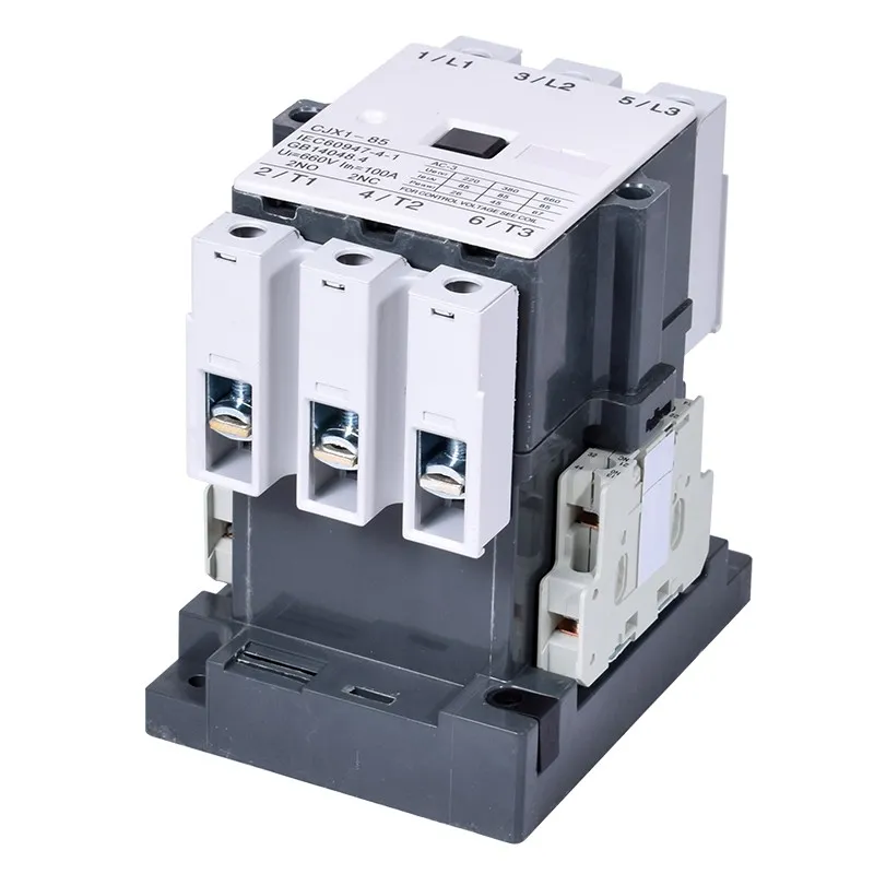
CJX2-32
32AAC-3
The most suitable contactor model for your load conditions
Technical Parameters
Rated Operating Current (AC-3)
32A
Rated Insulation Voltage
690V
Coil Voltage
220V/380V
Auxiliary Contacts
1NO+1NC
Mechanical Life
10 Million Cycles
Electrical Life (AC-3)
1 Million Cycles
Alternative Options
Calculation Parameters Details
Load Type
Motor Load
Calculation Power
7.5 kW
Rated Voltage
380 V
Rated Current
14.5 A
Start Current
87 A
Usage Category
AC-3
Selection Factor
1.5
Calculated Contactor Current
21.8 A
Current Curve
Electrical Symbols and Wiring Diagrams
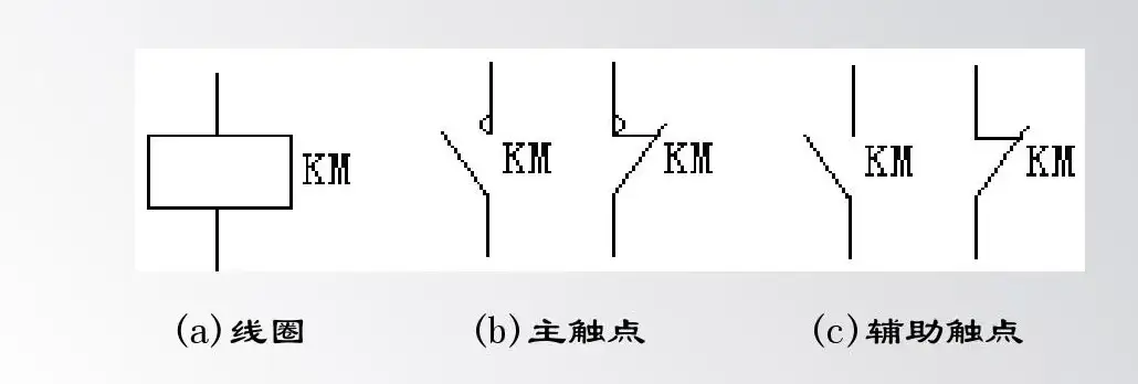
Electrical Symbol
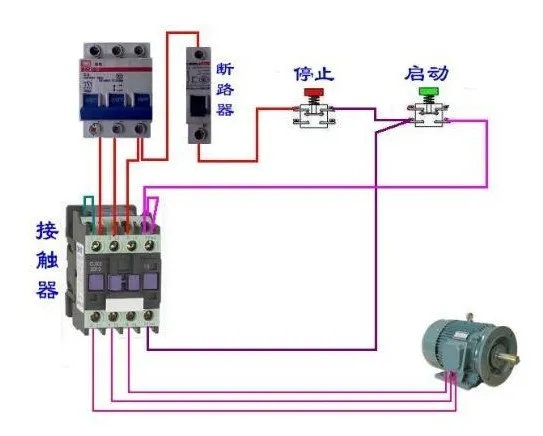
Direct Start Wiring Diagram
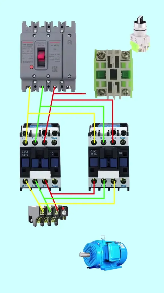
Star-Delta Start Wiring Diagram
Wiring Instructions
Main circuit power should be connected from the top of the contactor, and the load from the bottom
Control circuit should be wired correctly according to the coil voltage
Auxiliary contacts can be used for self-locking, interlocking or signal indication
Be sure to install appropriate protective devices (such as fuses, thermal relays)
After wiring is completed, check the insulation resistance to ensure safety
Disclaimer
This tool is for reference only. Actual selection should be verified according to specific application scenarios and relevant standards. It is recommended to use under the guidance of professional electrical engineers. This website assumes no responsibility for any consequences arising from the use of this tool.
---
# Application and Advantages of Smart Power Distribution Systems in Modern Factories
源地址: https://www.lyskjd.com/en/articles/2/
摘要: With the advancement of Industry 4.0, smart power distribution systems have become the core of energy management in modern factories. This article combines practical cases to analyze how smart power distribution systems achieve energy monitoring, load management, and fault warning, as well as the energy-saving benefits they bring to enterprises.
With the rapid development of Industry 4.0 and intelligent manufacturing, traditional power distribution systems can no longer meet the needs of modern factories for energy management, equipment monitoring, and fault warning. As an important part of industrial automation, smart power distribution systems are gradually becoming the core solution for energy management in modern factories.
## 1. Core Components of Smart Power Distribution Systems
Smart power distribution systems are integrated systems that incorporate multiple advanced technologies, mainly composed of the following core components:
### 1. Smart Power Distribution Equipment
Including smart circuit breakers, smart switchgear, smart meters, smart sensors, etc. These devices have data acquisition, communication, and remote control functions, and can real-time monitor equipment operating status and power quality.
### 2. Communication Network
Using industrial Ethernet, fieldbus, and other communication technologies to realize data transmission and interconnection between devices, building a reliable industrial communication network.
### 3. Monitoring and Management Platform
A monitoring and management platform based on cloud computing and big data technology, which can realize data acquisition, real-time monitoring, data analysis, fault warning, and report generation functions, providing users with comprehensive energy management solutions.
### 4. Edge Computing Nodes
Deploy computing nodes at the edge close to the equipment to realize local processing and real-time analysis of data, reducing data transmission delay and improving system response speed.
## 2. Main Functions of Smart Power Distribution Systems
### 1. Real-time Energy Monitoring
Smart power distribution systems can real-time monitor the power consumption of various areas and equipment in the factory, including voltage, current, power factor, harmonics, and other power quality parameters, helping enterprises fully understand energy usage conditions.
### 2. Load Management and Optimization
Through analysis of load data, the system can identify energy waste points and optimization opportunities, provide load optimization suggestions, help enterprises rationally allocate energy resources, and reduce energy consumption.
### 3. Fault Warning and Diagnosis
The system can real-time monitor equipment operating status, and through data analysis and machine learning algorithms, predict possible faults in advance, and provide fault diagnosis and maintenance suggestions, reducing equipment downtime and improving production efficiency.
### 4. Power Quality Analysis
Smart power distribution systems can comprehensively analyze power quality, including harmonics, voltage fluctuations, frequency deviations, etc., helping enterprises identify power quality problems and take corresponding governance measures.
### 5. Remote Control and Management
Users can remotely control power distribution equipment through the monitoring and management platform, realizing operations such as remote closing and opening, reducing on-site operations and improving management efficiency.
## 3. Application Cases of Smart Power Distribution Systems in Modern Factories
### Case 1: A Automotive Parts Manufacturing Factory
After adopting the smart power distribution system, the factory achieved the following effects:
- Energy consumption reduced by 15%, saving about 2 million yuan in electricity costs annually
- Equipment failure downtime reduced by 30%, improving production efficiency
- Power quality problems were effectively managed, and equipment life was extended by 20%
- Realized digitalization and visualization of energy management, improving management efficiency
### Case 2: An Electronic Manufacturing Factory
After introducing the smart power distribution system, the factory achieved remarkable results:
- Through load optimization, peak electricity demand was reduced by 12%, reducing demand electricity costs
- Realized real-time monitoring and fault warning of key equipment, avoiding multiple major equipment failures
- Through energy data analysis, identified multiple energy waste points, and saved a lot of energy costs after optimization
- Established a complete energy management system and passed ISO 50001 energy management system certification
## 4. Advantages of Smart Power Distribution Systems
### 1. Energy Saving and Consumption Reduction
Through real-time monitoring and load optimization, smart power distribution systems can help enterprises reduce energy consumption and energy cost expenditure.
### 2. Improve Equipment Reliability
Through fault warning and diagnosis functions, the system can detect equipment fault hidden dangers in advance, reduce equipment downtime, and improve production efficiency.
### 3. Improve Power Quality
Smart power distribution systems can comprehensively monitor and analyze power quality, helping enterprises solve power quality problems and extend equipment life.
### 4. Improve Management Efficiency
Through digital and visual management platforms, enterprises can realize automation and intelligence of energy management, improve management efficiency, and reduce management costs.
### 5. Support Intelligent Manufacturing
As an important part of Industry 4.0, smart power distribution systems can be integrated with other intelligent manufacturing systems to support enterprises in achieving comprehensive digital transformation.
## 5. Development Trends of Smart Power Distribution Systems
### 1. Wide Application of Edge Computing
With the development of edge computing technology, more and more data analysis and processing will be completed at the edge, improving system response speed and reliability.
### 2. Deep Integration of Artificial Intelligence and Machine Learning
By introducing artificial intelligence and machine learning algorithms, smart power distribution systems will have stronger predictive analysis capabilities, and can more accurately predict equipment faults and energy demand.
### 3. Application of 5G Communication Technology
The high bandwidth and low latency characteristics of 5G communication technology will provide more reliable communication support for smart power distribution systems, realizing more real-time data transmission and remote control.
### 4. Construction of Energy Internet
Smart power distribution systems will be integrated with renewable energy, energy storage systems, etc., to build an energy internet, realizing efficient utilization and optimal configuration of energy.
### 5. Standardization and Modular Design
Future smart power distribution systems will adopt standardized and modular design, improving system scalability and compatibility, reducing system integration difficulty and cost.
## 6. Conclusion
As the core solution for energy management in modern factories, smart power distribution systems have many advantages such as energy saving and consumption reduction, improving equipment reliability, improving power quality, and improving management efficiency. With the development of Industry 4.0 and intelligent manufacturing, the application of smart power distribution systems will become more and more widespread, becoming an important part of enterprises' digital transformation.
For enterprises, introducing smart power distribution systems can not only reduce energy costs and improve production efficiency, but also enhance enterprises' competitiveness and sustainable development capabilities. Therefore, enterprises should actively embrace smart power distribution technology, accelerate the digital transformation of energy management, and contribute to the realization of green manufacturing and sustainable development.
---
# Application and Development of Smart Power Distribution Systems in Industrial Fields
源地址: https://www.lyskjd.com/en/articles/smart-power-distribution-industrial/
摘要: This article details the current application status, technical characteristics, advantages, and future development trends of smart power distribution systems in industrial fields, providing a reference for industrial enterprises to achieve efficient, safe, and reliable power management.
## 1. Introduction
With the arrival of the Industry 4.0 era, industrial enterprises have put forward higher requirements for the reliability, safety, and energy efficiency management of power supply. Traditional power distribution systems can no longer meet the needs of modern industrial production, and smart power distribution systems have emerged. This article will deeply explore the current application status, core technologies, advantages, and future development trends of smart power distribution systems in industrial fields. Smart power distribution systems integrate a variety of advanced electrical equipment, including [High Voltage Switchgear](), [Low-Voltage Distribution Cabinets](), and support [Photovoltaic Power Generation]() and other new energy access.
## 2. Core Technologies of Smart Power Distribution Systems
### 2.1 IoT Technology
IoT technology is the foundation of smart power distribution systems, realizing interconnection and data sharing between devices by installing sensors and communication modules on power distribution equipment. It mainly includes:
- Wireless Sensor Networks (WSN)
- Industrial Ethernet
- 5G communication technology
- Low-power wide-area network technologies such as LoRaWAN
### 2.2 Big Data and Cloud Computing
The massive data generated by smart power distribution systems needs to be processed through big data analysis and cloud computing technologies to achieve:
- Real-time data collection and monitoring
- Fault prediction and diagnosis
- Energy efficiency analysis and optimization
- Trend prediction and decision support
### 2.3 Artificial Intelligence and Machine Learning
The applications of AI technology in smart power distribution systems mainly include:
- Anomaly detection and fault diagnosis
- Load forecasting and optimal scheduling
- Intelligent protection and self-healing control
- Predictive maintenance
## 3. Application Scenarios of Smart Power Distribution Systems in Industrial Fields
### 3.1 Industrial Enterprise Main Substation
In industrial enterprise main substations, smart power distribution systems can achieve:
- Intelligent monitoring and protection of high-voltage switchgear
- Condition monitoring and life management of transformers
- Intelligent control of reactive power compensation
- Harmonic monitoring and governance
### 3.2 Workshop Power Distribution Systems
At the workshop level, smart power distribution systems can achieve:
- Real-time monitoring of low-voltage distribution cabinets
- Intelligent control and protection of motors
- Dynamic monitoring and analysis of workshop loads
- Quick fault location and isolation
### 3.3 New Energy Access and Microgrids
For industrial enterprises connected to new energy sources, smart power distribution systems can achieve:
- Intelligent access to new energy sources such as photovoltaic and wind power
- Optimal scheduling of energy storage systems
- Coordinated control of microgrids
- Smooth switching between grid-connected and off-grid modes
## 4. Advantages of Smart Power Distribution Systems
### 4.1 Improved Power Supply Reliability
- Real-time monitoring of equipment status, early detection of potential faults
- Quick fault location and isolation, reducing power outage time
- Realization of self-healing control of power distribution systems
### 4.2 Enhanced Energy Efficiency Management
- Precise monitoring of energy consumption in each link, identifying energy-saving potential
- Optimized load distribution, reducing losses
- Realization of dynamic adjustment of reactive power compensation
### 4.3 Enhanced Operational Safety
- Real-time monitoring of electrical parameters, preventing overload, short circuit and other faults
- Realization of remote operation, reducing the risk of on-site operations for personnel
- Establishment of a complete safety early warning mechanism
### 4.4 Reduced Operation and Maintenance Costs
- Implementation of predictive maintenance, reducing unnecessary inspections
- Remote monitoring and diagnosis, reducing manual inspection costs
- Optimization of equipment operation, extending equipment service life
## 5. Case Study: Smart Power Distribution System for a Automobile Manufacturing Plant
### 5.1 Project Background
A large automobile manufacturing plant had problems such as aging equipment, backward monitoring methods, and lack of energy efficiency management in its original power distribution system, and planned to upgrade to a smart power distribution system.
### 5.2 System Architecture
- **Perception Layer**: Install smart meters, temperature sensors, humidity sensors, vibration sensors and other equipment
- **Network Layer**: Adopt industrial Ethernet and wireless communication technologies to realize equipment interconnection
- **Platform Layer**: Establish a smart power distribution monitoring platform to realize data collection, storage, analysis and visualization
- **Application Layer**: Provide functions such as equipment monitoring, energy efficiency management, fault diagnosis, and report analysis
### 5.3 Implementation Effects
- Power supply reliability improved to 99.99%
- Energy utilization rate increased by 15%
- Operation and maintenance costs reduced by 30%
- Fault response time shortened by 80%
## 6. Future Development Trends of Smart Power Distribution Systems
### 6.1 Digital Transformation
With the development of digital twin technology, smart power distribution systems will realize real-time mapping between physical devices and digital models, improving the system's visualization and simulation capabilities.
### 6.2 Deep Integration with Edge Computing
Edge computing technology will be widely used in smart power distribution systems, realizing local data processing and real-time decision-making, reducing network latency and bandwidth pressure.
### 6.3 Multi-energy Coordination and Integrated Energy Management
Smart power distribution systems will deeply integrate with heating, gas supply and other systems, realizing coordinated optimization and integrated management of multiple energy sources.
### 6.4 Standardization and Openness
Future smart power distribution systems will pay more attention to standardization and openness, supporting interconnection and interoperability of equipment from different manufacturers.
## 7. Conclusion
Smart power distribution systems are an important means for industrial fields to achieve efficient, safe, and reliable power management, with broad application prospects. With the continuous development of IoT, big data, AI and other technologies, smart power distribution systems will develop in a more intelligent, digital, and standardized direction, providing strong support for the digital transformation of industrial enterprises.
## 8. References
1. "Smart Grid Technology Standard System"
2. "Industrial Internet of Things White Paper"
3. "Smart Power Distribution System Design Specification"
4. "Power System Automation" journal
## 9. Related Reading
- [Key Points of Smart Building Power Distribution System Design](/articles/smart-building-power-distribution)
- [Analysis of Industrial Automation Development Trends](/articles/industrial-automation-trends)
- [Research on New Energy Grid Connection Technology](/articles/new-energy-grid-connection)
---
# Application and Optimization of Photovoltaic Power Generation Technology in Industrial Field
源地址: https://www.lyskjd.com/en/articles/industrial-pv-generation-applications/
摘要: This article discusses the application status, system design points, economic benefit analysis, and future development trends of photovoltaic power generation technology in the industrial field, providing references for industrial enterprises to achieve green energy transformation.
## 1. Introduction
With the increasingly serious global energy crisis and environmental problems, industrial enterprises are facing enormous pressure to save energy and reduce emissions. As a clean and renewable energy form, photovoltaic power generation is gradually becoming an important choice for industrial enterprises to achieve green energy transformation. This article will deeply discuss the application status, system design points, economic benefit analysis, and future development trends of photovoltaic power generation technology in the industrial field.
## 2. Basic Principles and Development Status of Photovoltaic Power Generation Technology
### 2.1 Basic Principles of Photovoltaic Power Generation
Photovoltaic power generation is a technology that directly converts solar energy into electrical energy using the photovoltaic effect of semiconductor materials. Its basic principle is: when sunlight irradiates on photovoltaic cells, photons interact with electrons in semiconductor materials, causing electrons to gain enough energy to escape from atoms, forming free electrons and holes, thereby generating electromotive force.
### 2.2 Development Status of Photovoltaic Power Generation Technology
In recent years, photovoltaic power generation technology has developed rapidly, mainly manifested in:
- Continuous improvement of photovoltaic cell conversion efficiency, with monocrystalline silicon cell efficiency exceeding 26%
- Continuous decline in component costs, dropping by more than 90% in the past 10 years
- Increasingly mature system integration technology, with continuous improvement of power generation efficiency
- Rapid development of energy storage technology, solving the intermittency problem of photovoltaic power generation
## 3. Design Points of Photovoltaic Power Generation Systems in Industrial Field
### 3.1 Site Selection and Site Evaluation
When constructing photovoltaic power generation systems, industrial enterprises need to consider the following factors:
- Roof area and load-bearing capacity
- Solar resource conditions
- Grid connection conditions
- Surrounding environmental impact
### 3.2 System Capacity Design
System capacity design needs to consider:
- Enterprise electricity load characteristics
- Available roof area
- Local solar conditions
- Investment budget and payback period
### 3.3 Component Selection
Component selection needs to consider:
- Photovoltaic cell type (monocrystalline silicon, polycrystalline silicon, thin film)
- Component efficiency and lifespan
- Mechanical properties such as wind resistance and snow resistance
- Temperature coefficient and low-light performance
### 3.4 Inverter Selection
Inverter selection needs to consider:
- Inverter type (centralized, string, micro-inverter)
- Conversion efficiency
- Reliability and lifespan
- Grid connection performance and power quality
### 3.5 System Integration and Installation
System integration and installation need to consider:
- Component arrangement and tilt angle design
- Bracket system selection
- Cable routing and protection
- Grounding and lightning protection design
## 4. Application Cases of Photovoltaic Power Generation Systems in Industrial Field
### 4.1 Roof Photovoltaic Power Generation Project of an Electronic Factory
#### Project Overview
- Installed capacity: 5MWp
- Component type: Monocrystalline silicon components
- Inverter type: String inverter
- Annual power generation: About 5.5 million kWh
- Floor area: About 45,000 square meters
#### Implementation Effect
- Annual electricity cost saving: About 3.85 million yuan
- Annual carbon dioxide emission reduction: About 4,400 tons
- Investment payback period: About 5.5 years
- Equipment utilization rate: About 98%
### 4.2 Distributed Photovoltaic Power Generation Project of an Automotive Parts Manufacturer
#### Project Overview
- Installed capacity: 2MWp
- Component type: High-efficiency monocrystalline silicon components
- Inverter type: Centralized inverter
- Annual power generation: About 2.2 million kWh
- Floor area: About 18,000 square meters
#### Implementation Effect
- Annual electricity cost saving: About 1.54 million yuan
- Annual carbon dioxide emission reduction: About 1,760 tons
- Investment payback period: About 6 years
- Self-consumption rate: About 95%
## 5. Economic Benefit Analysis of Industrial Photovoltaic Power Generation Systems
### 5.1 Investment Cost Composition
The investment cost of industrial photovoltaic power generation systems mainly includes:
- Photovoltaic component cost (about 50%)
- Inverter cost (about 15%)
- Bracket and installation cost (about 15%)
- Cable and electrical equipment cost (about 10%)
- Design, commissioning, and operation and maintenance cost (about 10%)
### 5.2 Revenue Sources
The revenue of industrial photovoltaic power generation systems mainly includes:
- Saved electricity expenses
- National and local subsidy policies
- Carbon trading revenue
- Peak-valley electricity price difference revenue
### 5.3 Investment Return Analysis
Investment return analysis needs to consider:
- Initial investment cost
- Annual power generation and revenue
- Operation and maintenance costs
- Inflation rate
- Discount rate
## 6. Optimization Strategies for Industrial Photovoltaic Power Generation Systems
### 6.1 Improving System Power Generation Efficiency
- Select high-efficiency photovoltaic components
- Optimize component arrangement and tilt angle
- Adopt tracking systems
- Strengthen component cleaning and maintenance
### 6.2 Improving Self-consumption Rate
- Combine with enterprise electricity load characteristics to optimize system design
- Configure energy storage systems to achieve peak-valley regulation
- Adopt intelligent control systems to optimize energy dispatching
### 6.3 Reducing Operation and Maintenance Costs
- Adopt intelligent operation and maintenance management systems
- Implement remote monitoring and diagnosis
- Establish predictive maintenance mechanisms
### 6.4 Improving System Reliability
- Select high-reliability equipment
- Optimize system design to improve redundancy
- Strengthen lightning protection, bird prevention, and pollution prevention measures
## 7. Future Development Trends of Industrial Photovoltaic Power Generation
### 7.1 Technology Development Trends
- Further improvement of photovoltaic cell efficiency
- Wide application of bifacial power generation technology
- Commercialization of new battery technologies such as perovskite
- Deep integration of photovoltaics and energy storage
### 7.2 Application Model Innovation
- Building-integrated photovoltaics (BIPV)
- Photovoltaic + energy storage + microgrid mode
- Virtual power plant technology application
- Green power trading mechanism
### 7.3 Policy and Market Environment
- Promotion of carbon peak and carbon neutrality policies
- Improvement of green manufacturing standard system
- Deepening of power market reform
- Market-oriented trading of distributed energy
## 8. Conclusion
Photovoltaic power generation technology has broad application prospects in the industrial field, which can not only help industrial enterprises reduce energy costs but also reduce carbon emissions and achieve green manufacturing. With the continuous advancement of technology and policy support, photovoltaic power generation will play an increasingly important role in the industrial field. Industrial enterprises should reasonably plan and design photovoltaic power generation systems according to their actual conditions, optimize operation management, and improve economic and environmental benefits.
## 9. References
1. "Photovoltaic Power Generation System Design Specifications"
2. "Interim Measures for the Management of Distributed Photovoltaic Power Generation Projects"
3. "Industrial Energy Conservation Diagnosis Service Action Plan"
4. "14th Five-Year Plan for Solar Photovoltaic Industry Development"
## 10. Related Reading
- [Application and Development of Smart Power Distribution Systems in Industrial Field](/articles/smart-power-distribution-industrial)
- [Application and Optimization of Energy Storage Systems in Industrial Enterprises](/articles/industrial-energy-storage-optimization)
- [Evaluation Standards and Practice for Green Factories](/articles/green-factory-evaluation)
---
# Busbar Selection Calculator - Busbar Specification & Voltage Drop Calculation Tool
源地址: https://www.lyskjd.com/en/tools/busbar-calculation/
摘要: Professional busbar selection calculator, an online tool for calculating busbar specifications and voltage drop, supporting single-phase and three-phase systems, providing accurate busbar specification recommendations and voltage drop calculations to help engineers quickly complete busbar system design.
Disclaimer
This tool is for reference only. Please verify actual selection according to specific application scenarios and relevant standards. It is recommended to use under the guidance of a professional electrical engineer. This website does not assume any responsibility for any consequences arising from the use of this tool.
---
# Cable Ampacity Calculator - Cable Allowable Ampacity Calculation Tool
源地址: https://www.lyskjd.com/en/tools/cable-ampacity-calculator/
摘要: Professional cable ampacity calculator that calculates the allowable ampacity of cables based on conductor material, insulation type, installation method, ambient temperature and other parameters, providing accurate ampacity calculation results and selection recommendations to help engineers quickly complete cable system design.
Calculation Results
Ampacity Parameters
Base Ampacity
-
Ambient Temperature Correction Factor
-
Conductor Count Correction Factor
-
Allowable Ampacity
-
Selection Suggestions
Recommended Maximum Load Current
-
Recommended Breaker Rated Current
-
Spacing Requirement
-
Temperature Limit
-
Calculation Instructions
-
Disclaimer
This tool is for reference only. Please verify actual selection according to specific application scenarios and relevant standards. It is recommended to use under the guidance of a professional electrical engineer. This website does not assume any responsibility for any consequences arising from the use of this tool.
---
# Cable Selection Calculator - Cable Cross-sectional Area & Voltage Drop Calculation Tool
源地址: https://www.lyskjd.com/en/tools/cable-selection/
摘要: Professional cable selection calculator, an online tool for calculating cable cross-sectional area and voltage drop, supporting single-phase and three-phase systems, with copper and aluminum materials optional, providing accurate cable size recommendations and voltage drop calculations.
Disclaimer
This tool is for reference only. Please verify actual selection according to specific application scenarios and relevant standards. It is recommended to use under the guidance of a professional electrical engineer. This website does not assume any responsibility for any consequences arising from the use of this tool.
---
# Circuit Breaker Selection Calculator - Intelligent Circuit Breaker Model Recommendation Tool
源地址: https://www.lyskjd.com/en/tools/circuit-breaker-selection/
摘要: Professional circuit breaker selection calculator that recommends appropriate circuit breaker models based on load current, voltage, trip characteristic and other parameters, providing accurate circuit breaker selection results and professional suggestions to help engineers quickly complete circuit breaker system design.
Selection Results
Recommended Model
Rated Current
Trip Characteristic
Number of Poles
-
-
-
-
Selection Suggestions
-
Disclaimer
This tool is for reference only. Please verify actual selection according to specific application scenarios and relevant standards. It is recommended to use under the guidance of a professional electrical engineer. This website does not assume any responsibility for any consequences arising from the use of this tool.
---
# Complete PLC Control Cabinet Guide: From Working Principles to Industrial Applications
源地址: https://www.lyskjd.com/en/articles/plc-control-system-guide/
摘要: PLC (Programmable Logic Controller) is the core brain of industrial automation. This article explains in plain language the definition, working principles, hardware structure, programming languages, application scenarios, and selection points of PLCs, and compares PLCs with relays, microcontrollers, and industrial PCs, helping readers with zero foundation quickly build a complete understanding of PLC control systems.
If you walk into any modern factory, you can almost always find a metal cabinet filled with buttons, indicator lights, and cables, quietly running and directing the rhythm of the entire production line — this is the **PLC control cabinet**. It is the "brain" of the industrial automation system, determining when machines start, stop, and alarm. This article will use plain language to help you understand PLC control cabinets from scratch.

## I. What is a PLC? — Installing a "Brain" for Industrial Machines
### 1.1 Definition of PLC
A PLC (Programmable Logic Controller) is a digital electronic operating system designed specifically for industrial environments. It internally stores instructions for performing logic operations, sequential control, timing, counting, and arithmetic operations, and controls various types of mechanical equipment or production processes through digital or analog inputs and outputs.
Simply put, a PLC is an **"industrial-grade mini-computer"**, but it's more rugged than a regular computer — it can operate stably in harsh environments with dust, vibration, high temperatures, and electromagnetic interference.
### 1.2 The Birth of PLC: Starting from the Automotive Production Line
The story of PLC begins with the American automotive industry in the 1960s. At that time, General Motors (GM) had to rewire relay control cabinets every time they changed production line models — often involving hundreds or thousands of relays, and changing wiring once meant weeks of downtime, wasting time and effort.
In 1968, GM published the famous "Ten Specifications," hoping to find a controller that was as flexible as a computer and as reliable as a relay. In 1969, Bedford Associates delivered the world's first PLC — the MODICON 084. From then on, **changing a production line only required modifying the program, not rewiring**, and industrial control entered the software era.
> 💡 Interestingly, the "Controller" in PLC's English name Programmable Logic Controller was deliberately chosen over "Computer" in early patents to emphasize that it is a "controller" rather than a "computer" — reliability was the top priority.
## II. How Does a PLC Work? — The Mystery of the Scan Cycle
The key to understanding how a PLC works lies in one word: **Scan Cycle**.
### 2.1 The Three-Step Loop
Unlike the human brain which responds "at any time," a PLC works in a **cyclic scanning** mode. Each scan cycle includes three phases:
1Input Sampling Phase: The PLC reads the status of all input terminals (whether buttons are pressed, whether sensors are triggered) and stores the results in the "input image register." Changes in external signals are not immediately responded to at this point.
2Program Execution Phase: The PLC executes the user-written program from top to bottom, left to right, performing logic operations based on the input image register and internal states, and writes the results to the "output image register."
3Output Refresh Phase: The PLC sends the contents of the output image register to the output terminals to drive actuators such as contactors and solenoid valves. Then it enters the next scan cycle.
### 2.2 How Fast is the Scan Cycle?
Modern PLC scan cycles are typically between **1~50 milliseconds**, meaning the PLC can complete dozens to hundreds of "read-compute-output" cycles per second. For most industrial processes (such as temperature control, production line tempo), this speed is more than sufficient.
> ⚠️ But note: if the program is too long or too complex, the scan cycle will lengthen, which may cause delayed response to fast signals. Therefore, PLC programming emphasizes "concise and efficient."
## III. Opening Up a PLC Control Cabinet: What's Inside?

A complete [PLC control cabinet]() consists of the following main parts, from outside to inside:
### 3.1 PLC Host (CPU Module)
This is the "brain core" of the control cabinet, responsible for storing programs, executing operations, and scheduling communications. CPUs of different levels vary significantly in scan speed, program capacity, and instruction set:
| CPU Level | Scan Cycle | Program Capacity | Typical Application |
|-----------|-----------|-----------------|---------------------|
| Small | 0.5~2ms | Several KB~tens of KB | Single equipment, small lines |
| Medium | 0.1~0.5ms | Tens of KB~hundreds of KB | Medium lines, process control |
| Large | <0.1ms | Hundreds of KB~several MB | Large factories, distributed systems |
### 3.2 I/O Modules — The PLC's "Eyes" and "Hands"
I/O (Input/Output) modules are the bridge for communication between the PLC and field devices:
- **Digital Input (DI)**: Receives on/off signals from buttons, limit switches, proximity switches
- **Digital Output (DO)**: Drives contactors, relays, solenoid valves, indicator lights
- **Analog Input (AI)**: Collects continuously changing signals such as temperature, pressure, flow, level (4-20mA/0-10V)
- **Analog Output (AO)**: Outputs continuous control signals, such as sending speed commands to a VFD

### 3.3 Communication Modules — Letting Devices "Talk"
Modern industry emphasizes "networking." PLCs exchange data with host computers, VFDs, touch screens and other devices through communication modules. Common protocols include:
- **Modbus RTU/TCP**: The most universal industrial protocol, supported by almost all devices
- **Profibus/Profinet**: Mainstream protocols in the Siemens ecosystem
- **Ethernet**: Used for remote monitoring and big data acquisition
For the application of communication networking in smart power distribution systems, see [Application and Development of Smart Power Distribution Systems in Industrial Fields]().
### 3.4 HMI Human-Machine Interface — The Window Between Human and Machine
The HMI (Human-Machine Interface) is typically a color touch screen that displays process flowcharts, operating parameters, and alarm information in real time. Operators can start/stop equipment and modify parameters on the screen. It makes complex control systems "visualized."
### 3.5 Electrical Control Components
The cabinet is also equipped with circuit breakers, contactors, thermal relays, switching power supplies and other electrical components for switching, protection, and isolation of the main circuit. For the selection methods of these components, see [Industrial Low-Voltage Distribution Cabinet Selection Guide and Application Practice]().

## IV. What Language Does a PLC Use? — Five Languages of IEC 61131-3
Many people think PLC programming is difficult, but the international standard IEC 61131-3 defines five programming languages, each with its own characteristics — there's always one for you:
### 4.1 Ladder Diagram (LD) — The Electrician's Favorite
The ladder diagram looks like a relay control circuit diagram, with two vertical lines on the left and right like the sides of a "ladder," and contacts and coils in between. It's intuitive and easy to understand, making it the **most commonly used PLC programming language**, especially popular among electrical engineers.
```
| Start Btn Stop Btn Coil |
|----[ ]--------[/]-------------( )---|
| | |
| Seal-in Contact |
|----[ ]------------------------------|
```
### 4.2 Function Block Diagram (FBD) — Building Block Programming
FBD combines logic using "function blocks" like building blocks. Each block performs a function (such as timing, counting, PID), and outputs can be connected to other blocks' inputs. It's suitable for modular design of complex logic.
### 4.3 Sequential Function Chart (SFC) — Flowchart Thinking
SFC describes process flows using "steps" and "transitions," particularly suitable for sequential control scenarios (such as a filling line: bottle in → fill → cap → bottle out).
### 4.4 Instruction List (IL) — The PLC's "Assembly Language"
IL is similar to assembly language, written with text instructions. It has high execution efficiency but poor readability and is now rarely used.
### 4.5 Structured Text (ST) — Like Writing C
ST is a high-level text language that supports IF/THEN, FOR loops, and function calls. It's suitable for complex algorithms and data processing, and is increasingly favored by young engineers.
> 💡 In practice, engineers typically **mix multiple languages**: main logic in ladder diagram, complex calculations in structured text, flow control in sequential function chart — each playing to its strengths.
## V. What Can a PLC Do? — Five Application Scenarios

### 5.1 Production Line Automation
This is the PLC's most classic battlefield. From food filling to automotive assembly, PLCs control conveyor belt start/stop, robotic arm grasping, and workstation tempo. A modern production line may have dozens of PLCs working together, achieving whole-line linkage through industrial Ethernet.
### 5.2 Water Treatment and Environmental Protection
The influent pumps, aeration fans, dosing pumps, and dewatering machines of a sewage treatment plant are all automatically regulated by PLCs according to process curves. Combined with a SCADA host system, **unattended** operation can be achieved. PLCs can also adjust dosing amounts in real time based on influent/effluent water quality, ensuring compliance while saving chemicals.
### 5.3 HVAC
In large shopping mall central air conditioning systems, PLCs control the number of operating units and speeds of chillers, cooling towers, and water pumps based on return water temperature, achieving constant temperature and humidity while significantly saving energy. Here, PLCs often work with VFDs. For the principles of variable frequency speed regulation, see [Complete VFD Selection Guide]().
### 5.4 Power Monitoring
In power distribution rooms, PLCs collect voltage, current, and power factor of each circuit, achieving load monitoring, reactive power compensation, and fault alarms. Together with [Low-Voltage Distribution Cabinets]() and [XL-21 Power Distribution Cabinets](), they form a complete smart power distribution system.
### 5.5 Buildings and Municipal
Elevator control, traffic signals, bridge lighting, landscape fountains... these facilities we encounter daily all have PLCs behind them. It's reliable, durable, and programmable — the ideal choice for municipal engineering.
## VI. PLC vs Relay vs Microcontroller vs Industrial PC
Beginners often ask: since they're all control devices, why does industry specifically choose PLCs? Let's make it clear with one table:
Dimension
Relay Control
Microcontroller
PLC
Industrial PC
Reliability
Medium (contact wear)
Low (self-designed EMI)
High (industrial-grade)
Medium (fans/HDD)
Flexibility
Poor (rewire to change logic)
High (change program)
Highest
Dev Difficulty
Low
High (HW+SW)
Medium (LD easy to learn)
High (programming)
Cost
Low (simple logic)
Lowest
Medium
High
Scale
Simple logic
Small-batch products
Medium-large industrial
Complex data
Maintainability
Poor
Poor
Good (diagnostics)
Medium
In summary: **relays suit simple fixed logic, microcontrollers suit low-cost batch products, industrial PCs suit complex data processing, while PLCs are the best balance point for industrial field control** — reliable, flexible, easy to learn, and easy to maintain.
## VII. How Do PLCs Work with VFDs and Soft Starters?

In real engineering, PLCs rarely "fight alone." They typically serve as **upper-level controllers**, directing VFDs, soft starters, and other devices:
### 7.1 PLC + VFD
The PLC sends speed commands to the [VFD Control Cabinet]() through analog signals (0-10V/4-20mA) or communication (Modbus/Profinet), and the VFD adjusts motor speed accordingly. Meanwhile, the PLC reads the VFD's operating current and fault codes for closed-loop control and interlock protection.
Typical application: In a constant pressure water supply system, the PLC performs PID calculations based on pressure sensor feedback and outputs frequency commands to the VFD to maintain constant water pressure. For detailed principles, see [How VFDs Achieve Constant Pressure Water Supply: Principles and Practice]().
### 7.2 PLC + Soft Starter
For high-power motors that don't need speed regulation but need smooth starting, the PLC controls the start/stop of the [Online Soft Starter]() and receives its running/fault status signals. For soft starter selection methods, see [Complete Soft Starter Selection Guide]().
### 7.3 PLC + Distribution Cabinet
The PLC control cabinet itself requires a stable power supply, typically provided by [Low-Voltage Distribution Cabinets]() or [XL-21 Distribution Cabinets](). The three form a complete "distribution — control — drive" hierarchy, which is the standard architecture of industrial electrical systems.
## VIII. PLC Control Cabinet Selection Points

If you're considering purchasing a PLC control cabinet, focus on the following:
### 8.1 I/O Points — Leave Sufficient Margin
Count all digital input/output and analog input/output points on site, and **reserve 15%~20% expansion margin**. Production lines may add inspection stations or actuators later; without margin, you'd have to replace the CPU or add racks, which costs more.
### 8.2 CPU Performance — Match the Process
Simple logic can use a small CPU; when PID closed-loop, high-speed counting, or motion control is involved, a mid-to-high-end CPU is needed. Don't blindly pursue high performance — enough is good.
### 8.3 Communication Needs — Integration-Oriented
Clarify whether you need to connect to SCADA/MES systems, and whether you need to network with VFDs/instruments. Confirm communication protocols in advance to avoid "can't talk to each other" later.
### 8.4 Protection Grade — Depends on Environment
IP20 is sufficient for clean control rooms; IP54 for dusty workshop environments; IP65 and above for outdoor or wash-down environments. Our [OMNIMECH Series PLC Control Cabinet]() offers IP54/IP65 and other protection grades.
### 8.5 Brand and Ecosystem — Consider Maintenance
When choosing a PLC brand, consider the company's existing equipment system (same brand facilitates spare parts sharing and personnel maintenance), local technical support capabilities, and ease of use of programming software. Mainstream brands include Siemens, Mitsubishi, Schneider, Omron, and domestic brands such as Inovance and Xinje.
## IX. The Future of PLC: From "Island" to "Cloud"

With the advancement of Industry 4.0 and smart manufacturing, PLCs themselves are evolving:
### 9.1 Enhanced Edge Computing
New-generation PLCs have built-in web servers and database interfaces, enabling local data preprocessing to reduce reliance on the cloud and lower latency.
### 9.2 Deep Integration with IT Systems
Traditional PLCs were products of the OT (Operational Technology) world. Now they're connecting with the IT world's ERP, MES, and cloud platforms through protocols like OPC UA and MQTT, achieving "IT-OT convergence."
### 9.3 More Open Programming
Structured text based on IEC 61131-3 is becoming increasingly popular. Some manufacturers also support Python and C programming, lowering the barrier for IT talent to enter the industrial field.
### 9.4 Safety and Cybersecurity
In the past, PLCs mostly ran in closed intranets. Now that they're networked, they face cyber attack risks. Functional safety (SIL) and industrial cybersecurity have become new dimensions in PLC selection.
## X. Conclusion
The PLC control cabinet is the "brain" of industrial automation. With reliable hardware, flexible software, and rich I/O, it turns complex process flows into lines of executable logic. From automotive production lines to sewage treatment plants, from central air conditioning to power monitoring, PLCs are everywhere, guarding the operation of modern industry.
If you're planning an automation project, welcome to learn about our [OMNIMECH Series PLC Control Cabinet]() — supporting multi-brand PLC integration including Siemens, Mitsubishi, and Schneider, providing full-process customized services from requirement research, program writing to on-site commissioning. We can also provide supporting equipment such as [VFD Control Cabinets](), [Low-Voltage Distribution Cabinets](), and [Online Soft Starters]() to build a complete industrial automation solution.
> 📖 **Further Reading**
> - Want to learn about motor speed control? Read [Complete VFD Selection Guide]()
> - Want to learn about motor start protection? Read [Complete Soft Starter Selection Guide]()
> - Want to learn about distribution system design? Read [Industrial Low-Voltage Distribution Cabinet Selection Guide]()
> - Want to learn about smart distribution trends? Read [Application and Development of Smart Power Distribution Systems in Industrial Fields]()
Choosing the right PLC means installing a smart and reliable brain for your industrial system. We hope this article helps you build a complete understanding of PLC control systems.
---
# Complete Soft Starter Selection Guide: From Parameters to Applications
源地址: https://www.lyskjd.com/en/articles/soft-starter-selection-guide/
摘要: Soft starter selection is a critical step in industrial electrical design. Incorrect selection can lead to startup failure, equipment damage, or even safety incidents. This article systematically explains the core principles and common pitfalls of soft starter selection from the perspectives of motor parameters, load types, starting modes, protection functions, and environmental conditions, helping engineers make accurate and efficient selections.
Soft starter selection is one of the most overlooked yet unforgiving aspects of industrial electrical design. Undersize it, and the motor fails to start or trips repeatedly; oversize it, and you waste money while losing protection sensitivity; choose the wrong type, and you risk shortening equipment life or even causing safety incidents. Drawing from real-world engineering experience, this article walks you through every critical step of soft starter selection, helping you avoid 90% of common mistakes. If you need quick selection results, you can use our [Soft Starter Intelligent Selection Calculator]() to get precise model recommendations by simply entering motor parameters.

## I. Three Core Parameters You Must Know Before Selection
### 1.1 Motor Rated Power — The Starting Point
Motor rated power is the most fundamental basis for soft starter selection. The soft starter's rated power must be greater than or equal to the motor's rated power, with appropriate margins based on load type.
Light-load starting (fans, water pumps): Soft starter power ≥ motor power, no additional upsizing needed
Medium-load starting (compressors, conveyors): Upsize soft starter by 1~2 power ratings
Heavy-load starting (crushers, ball mills): Upsize soft starter by 2~3 power ratings, or choose a heavy-duty model
> ⚠️ Common Pitfall: Many engineers habitually upsize the soft starter by one rating "just in case." However, for light loads, excessive upsizing actually reduces overload protection sensitivity, making it impossible to effectively protect the motor.
### 1.2 Motor Rated Voltage — Determines the Product Series
Motor rated voltage directly determines which soft starter product series to choose:
| Voltage Level | Applicable Product Series | Typical Applications |
|--------------|--------------------------|---------------------|
| 380V | Low-voltage soft starters | Factory distribution, pump rooms, HVAC systems |
| 660V | Low-voltage soft starters (special specs) | Mines, metallurgy |
| 3kV/6kV/10kV | High-voltage solid-state soft starter cabinets | Large pump stations, mine main fans, cement mills |
For 380V low-voltage applications, our [GE300 Series Intelligent Bypass Soft Starter]() and [GE300 Series Intelligent Online Soft Starter]() cover the 18.5kW~630kW power range, meeting the vast majority of low-voltage application needs. For high-voltage applications, the [SKR-HV Series High-Voltage Solid-State Soft Starter Cabinet]() supports 3kV/6kV/10kV voltage levels with maximum power up to 3200kW.

### 1.3 Motor Rated Current — The Hard Constraint
Motor rated current is a hard constraint for soft starter selection. The soft starter's rated current must be greater than or equal to the motor's rated current — this is the basic prerequisite for ensuring safe equipment operation.
In practice, we recommend calculating as follows:
**Soft Starter Rated Current ≥ Motor Rated Current × Load Factor**
Where the load factor varies by load type:
- Standard loads: 1.0
- Heavy-duty loads: 1.1~1.3
- Frequent starting: 1.2~1.5
You can use the [Motor Starting Current Calculator]() to quickly calculate starting current and provide data support for your selection.
## II. Load Type — Determines Starting Mode and Selection Direction
Load type is the most critical factor in soft starter selection. Different loads have dramatically different starting characteristics, which directly determine the choice of starting mode and soft starter configuration.
### 2.1 Common Load Classification and Starting Characteristics
Load Type
Typical Equipment
Starting Torque Demand
Recommended Starting Mode
Selection Advice
Fans
Centrifugal fans, induced draft fans
Low→High (square torque)
Voltage ramp start
Standard model sufficient
Pumps
Centrifugal pumps, deep-well pumps
Low→Medium
Current limit + soft stop
Soft stop required (prevent water hammer)
Compressors
Air compressors, refrigeration compressors
Medium→High
Current limit / kick start
Upsize 1~2 ratings
Conveyors
Belt conveyors, chain conveyors
High (large static friction)
Kick + voltage ramp
Heavy-duty, upsize 2 ratings
Crushers
Jaw crushers, cone crushers
Very high
Kick + current limit
Heavy-duty, upsize 2~3 ratings
### 2.2 Special Requirements for Pump Loads — Soft Stop
Water pumps are one of the most common applications for soft starters, but many people focus only on "soft starting" while overlooking the importance of "soft stopping."
When a pump stops suddenly, the high-speed water flowing through the pipeline continues forward due to inertia, creating a massive pressure wave at the valve — this is the **water hammer effect**. Water hammer can cause pipeline vibration and noise in mild cases, and pipeline rupture, valve damage, or pump impeller deformation in severe cases.
Therefore, soft starters for pump applications **must have a soft stop function**. Soft stopping gradually reduces the motor terminal voltage, causing the pump speed to decrease slowly and the water flow in the pipeline to decelerate smoothly, thereby eliminating the water hammer effect.
Our [SKR6800 Series Intelligent Online Soft Starter]() and [SKR300 Series Intelligent Online Soft Starter Cabinet]() both come standard with soft stop functionality, with stop time adjustable from 0 to 60 seconds, perfectly suited for all types of pump applications.

### 2.3 Kick Start for Heavy-Duty Loads
Heavy-duty equipment such as crushers and ball mills have enormous static friction between the load and drive shaft when at rest. Standard voltage ramp starting may not overcome this static friction, causing the motor to stall.
**Kick start** mode applies a short-duration (0.1~2 seconds adjustable) high-voltage pulse at the beginning of the start sequence, generating sufficient starting torque to overcome static friction. Once the load "breaks free," it smoothly transitions to normal voltage ramp starting.
## III. Bypass Type vs. Online Type — The Critical Selection Decision
Soft starters are divided into **bypass type** and **online type** based on their operating mode. This is the most commonly confused concept in selection, as the two differ significantly in structure, performance, and applicable scenarios.

### 3.1 Bypass Type Soft Starter
After the motor starts, a bypass type soft starter shorts out the thyristors through a built-in bypass contactor, and the motor runs directly from the utility power supply.
**Advantages:**
- Low operating energy consumption — bypass contactor conduction resistance is far lower than thyristors, resulting in minimal operating losses
- Low thyristor heat generation — thyristors disengage after starting, reducing cooling requirements
- Lower cost — relatively simple structure, more affordable pricing
**Applicable Scenarios:** Situations requiring only starting protection without speed regulation or continuous protection during operation, such as standard fans, pumps, and air compressors.
Recommended Product: [GE300 Series Intelligent Bypass Soft Starter]()
### 3.2 Online Type Soft Starter
After the motor starts, an online type soft starter keeps the thyristors fully conducting, and the motor always runs through the thyristors.
**Advantages:**
- Real-time protection — continuously monitors motor operating status and can respond instantly to overload, phase loss, and other faults
- Soft stop function — enables smooth stopping, eliminating water hammer effect
- Comprehensive operating monitoring — real-time display of current, voltage, power, and other operating parameters
- Strong communication capability — supports RS485/Modbus and other communication protocols for easy system integration
**Applicable Scenarios:** Situations requiring real-time protection, soft stopping, or remote monitoring, such as water supply pump stations, fire pumps, and central air conditioning systems.
Recommended Products: [GE300 Series Intelligent Online Soft Starter](), [SKR6800 Series Intelligent Online Soft Starter]()

### 3.3 How to Choose?
Comparison Dimension
Bypass Type
Online Type
Operating Energy Consumption
Very low (bypass contactor conduction)
Slightly higher (thyristor full conduction voltage drop)
Real-time Protection
Effective during starting phase
Effective throughout operation
Soft Stop
Not supported
Supported
Operating Monitoring
Basic parameters
Comprehensive monitoring + communication
Price
Lower
Slightly higher
Typical Applications
Fans, air compressors
Pumps, fire pumps, HVAC
> 💡 Selection Advice: If you only need starting protection, the bypass type is more economical. If you need soft stopping, real-time protection, or remote monitoring, you must choose the online type. For more technical details on bypass vs. online types, refer to [Soft Starter Core Advantages Comparison: Redefining Efficiency and Reliability in Motor Control]().
## IV. Protection Functions — The Safety Baseline for Selection
A soft starter's protection functions are the last line of defense for safe motor operation. Protection capabilities vary significantly between brands and models, so you must verify the following core protection functions during selection:
### 4.1 Essential Protection Functions
Overload Protection: Prevents motor from running overloaded for extended periods, which can burn out windings. Overload class should be adjustable (typically 1~30 classes) to match different load characteristics
Phase Loss Protection: Input/output phase loss detection, prevents motor burnout from single-phase operation
Overvoltage/Undervoltage Protection: Monitors power grid voltage anomalies, prevents motor operation under abnormal voltage
Three-Phase Imbalance Protection: Detects three-phase current imbalance, prevents motor damage from unbalanced operation
### 4.2 Advanced Protection Functions
For critical equipment or harsh operating conditions, also consider these advanced protection functions:
- **Stall/Jam Protection**: Rapidly cuts power when motor speed stagnates during starting
- **Ground Fault Protection**: Detects motor winding ground faults
- **Underload Protection**: Detects pump dry-running, belt breakage, and other underload conditions
- **Phase Sequence Protection**: Prevents motor reverse rotation due to incorrect power phase sequence
- **External Fault Interface**: Receives external temperature, pressure, and other sensor signals to trigger protection
Our GE300 series soft starters feature **24 comprehensive protection functions** covering all the above protection needs. For detailed information, refer to the [GE300 Series Soft Starter User Manual]().
## V. Environmental Conditions — The Often-Overlooked Factor
### 5.1 Ambient Temperature
A soft starter's rated current is specified at a reference ambient temperature (typically 40°C). When the installation ambient temperature exceeds 40°C, derating must be applied as follows:
**Actual Available Current = Rated Current × Derating Factor**
| Ambient Temperature | Derating Factor |
|--------------------|----------------|
| ≤40°C | 1.0 |
| 45°C | 0.95 |
| 50°C | 0.90 |
| 55°C | 0.85 |
| 60°C | 0.80 |
> ⚠️ If the ambient temperature exceeds 60°C, we recommend selecting a soft starter one size larger or improving ventilation and cooling conditions in the installation environment.
### 5.2 Altitude
Above 1000 meters altitude, reduced air density decreases cooling capacity and air insulation strength. Derating is required above 1000 meters:
- 1000~2000m: Current derating 5%
- 2000~3000m: Current derating 10%
- Above 3000m: Consult the manufacturer for customized solutions
### 5.3 Protection Rating
Choose the appropriate protection rating based on the installation environment:
- **IP20**: Installation inside standard distribution cabinets, dry and clean environments
- **IP40**: Environments with higher dust protection requirements
- **IP54**: Humid, dusty environments such as pump rooms and outdoor installations
For applications requiring standalone installation (not inside a distribution cabinet), we recommend the [SKR300 Series Intelligent Online Soft Starter Cabinet](), whose cabinet design provides a higher protection rating and more comprehensive cooling solution.

## VI. Soft Starter vs. VFD — When Should You Choose a VFD?
During the selection process, many engineers struggle with the question: should I choose a soft starter or a VFD? The core difference between the two is:
- **Soft Starter**: Only controls the starting/stopping process; the motor runs at full speed during operation — **no speed regulation capability**
- **VFD (Variable Frequency Drive)**: Controls motor speed throughout operation, enabling **stepless speed adjustment**, but at a higher cost
### 6.1 When to Choose a Soft Starter
- The motor always runs at rated speed with no need for speed adjustment
- You only need to solve starting current impact issues
- Budget is limited, seeking cost-effectiveness
- The installation environment has strict harmonic requirements (soft starters produce no harmonics)
For more advantages of soft starters compared to VFDs, refer to [Soft Starter Core Advantages Comparison: Stability as the Core, Building the Foundation of Industrial Operation]().
### 6.2 When to Choose a VFD
- You need to adjust motor speed based on process requirements (e.g., constant pressure water supply, fan airflow regulation)
- Significant energy savings are needed (fan and pump speed regulation can save 20%~50% energy)
- Precise speed control or torque control is required
If you determine that a VFD is needed, you can use the [VFD Selection Tool]() for quick selection, or learn about our [SK600 Series General-Purpose Vector VFD]() and [VFD Control Cabinet]() product lines. For VFD applications in constant pressure water supply, refer to [How VFDs Achieve Constant Pressure Water Supply: Principles and Practice]().

## VII. Selection Process Summary
Combining all the factors above, soft starter selection can follow this standardized process:
1Determine Motor Parameters: Rated power, rated voltage, rated current, power factor
2Analyze Load Type: Light/medium/heavy load, whether soft stop or kick start is needed
3Choose Operating Mode: Bypass type (economical) or online type (full-featured)
6Finalize Specifications: Integrate all factors to determine the soft starter model and power rating
## VIII. Common Selection Mistakes and How to Avoid Them
### Mistake 1: Bigger Is Always Better
Many engineers habitually upsize the soft starter by 2~3 power ratings for "insurance." In reality, excessive upsizing leads to:
- Reduced overload protection sensitivity, making it impossible to effectively protect the motor
- Decreased starting current limiting precision
- Wasted cost
**Correct Approach**: Choose the appropriate upsizing factor based on load type — no upsizing for light loads, 1~3 ratings for heavy loads.
### Mistake 2: Ignoring Starting Frequency
If the motor requires frequent starting (e.g., more than 10 starts per hour), the soft starter's thyristors generate substantial heat. A standard soft starter may fail to operate properly due to overheat protection.
**Correct Approach**: For frequent starting applications, choose a heavy-duty model or one with enhanced cooling specifications, and inform the supplier of the actual starting frequency during selection.
### Mistake 3: Confusing Bypass and Online Types
Some users purchase a bypass type soft starter but expect it to provide soft stop functionality — this is impossible. In a bypass type, the thyristors are shorted out after starting, so the stopping process cannot be controlled.
**Correct Approach**: When soft stop functionality is required, you must choose an online type soft starter.
### Mistake 4: Neglecting Grid Capacity
In weak grid environments (small transformer capacity or long power supply lines), even with a soft starter, the starting current may still cause grid voltage dips that affect other equipment on the same grid.
**Correct Approach**: In weak grid environments, use current limit starting mode and set the current limit multiplier to a lower level (e.g., 2× rated current). If necessary, consult the power utility to confirm grid capacity. For the role of soft starters in smart power distribution systems, refer to [Application and Advantages of Smart Power Distribution Systems in Modern Factories]() and [Application and Development of Smart Power Distribution Systems in Industrial Fields]().
## IX. Quick Selection Reference Table
## X. Final Thoughts
Soft starter selection may seem straightforward, but it actually involves comprehensive consideration across multiple dimensions: motor parameters, load characteristics, operating mode, protection requirements, and environmental conditions. The core principle of selection is: **choose the type based on load characteristics, choose the specifications based on motor parameters, and make corrections based on environmental conditions**.
If you still have questions during the selection process, here are ways to get professional support:
1. Use the [Soft Starter Intelligent Selection Calculator]() for quick selection recommendations
2. Refer to the [GE300 Series Soft Starter User Manual]() for detailed technical parameters
3. Contact our technical advisors for one-on-one selection guidance
For overall low-voltage distribution system selection, refer to [Industrial Low-Voltage Distribution Cabinet Selection Guide and Application Practice](); for high-voltage distribution equipment selection, refer to [Technical Features and Selection Guide for High Voltage Switchgear](); for comparison with traditional reduced-voltage starting solutions, learn about the technical features of the [Autotransformer Reduced Voltage Starting Cabinet]().
Choosing the right soft starter is not just about protecting your equipment — it's about safeguarding the stable operation of your entire production system. We hope this article helps you avoid common pitfalls and get it right the first time.
---
# Complete VFD Selection Guide: From Load Analysis to Model Determination
源地址: https://www.lyskjd.com/en/articles/vfd-selection-guide/
摘要: VFD selection is a core aspect of industrial automation projects. Incorrect selection can lead to unstable operation, reduced energy savings, equipment damage, or even production line shutdowns. This article systematically explains the key principles and common pitfalls of VFD selection from the perspectives of load characteristics, control methods, power matching, environmental conditions, and communication requirements, helping engineers make accurate and efficient selections.
Variable Frequency Drives (VFDs) are among the most widely used motor control devices in industrial automation, but the problems caused by incorrect selection are equally common — from unstable operation and diminished energy savings to frequent tripping, equipment damage, and production line shutdowns. Unlike soft starters, VFDs not only control the starting process but also regulate motor speed throughout operation, making selection more multidimensional and technically demanding. This article walks you through every critical step of VFD selection based on real-world engineering experience. If you need quick selection results, you can use our [VFD Intelligent Selection System]() to get precise model recommendations by simply entering motor parameters.

## I. Selection Step One: Understand Your Load Characteristics
Load characteristics are the fundamental starting point for VFD selection. Different loads impose completely different requirements on the VFD. Before selecting, you must answer one question: **Is your load constant torque or variable torque?**
### 1.1 Constant Torque Loads
Constant torque loads are characterized by the fact that regardless of speed changes, the torque required by the load remains essentially constant. Typical equipment includes:
- Conveyors, belt conveyors
- Extruders, injection molding machines
- Hoists, cranes
- Mixers, internal mixers
**Selection Key Points**: Constant torque loads require sufficient torque output across the entire speed range. The VFD must be selected based on the motor's rated current, with particular attention to low-frequency torque output capability. We recommend choosing a VFD that supports vector control, such as the [SK600 Series General-Purpose Vector VFD](), which can output 150% starting torque at 0.5Hz (SVC mode), fully meeting the drive requirements of constant torque loads.
### 1.2 Variable Torque Loads (Fans and Pumps)
Variable torque loads are characterized by torque being proportional to the square of speed and power being proportional to the cube of speed. Typical equipment includes:
- Centrifugal fans, induced draft fans
- Centrifugal pumps, deep-well pumps
- HVAC units, cooling towers
**Selection Key Points**: Variable torque loads require very little torque at low-frequency operation, so low-frequency torque requirements for the VFD are not demanding — V/F control is usually sufficient. More importantly, the **energy savings** are significant — according to the affinity laws, a 20% reduction in speed can reduce power consumption by approximately 50%. This is the core reason VFDs are widely applied in fan and pump applications. For detailed information on VFD applications in constant pressure water supply, refer to [How VFDs Achieve Constant Pressure Water Supply: Principles and Practice]().

### 1.3 Quick Comparison of Selection Differences
Comparison Dimension
Constant Torque Load
Variable Torque Load
Recommended Control Method
Vector Control (SVC/FVC)
V/F Control
Power Selection
≥ Motor power, upsize 1~2 ratings for heavy loads
≥ Motor power sufficient
Low-Frequency Torque Requirement
High (150%+ starting torque needed)
Low (light load at low frequency)
Speed Range
Typically 1:10~1:50
Typically 1:2~1:4
Energy Savings Potential
Limited (mainly through process optimization)
Significant (20%~50%)
Typical Applications
Conveyors, extruders, hoists
Fans, pumps, HVAC
## II. Power Matching — The Hard Metric for Selection
Power matching is the most fundamental and critical aspect of VFD selection. Many engineers habitually match motor power "one-to-one," but actual selection is far more complex.
### 2.1 Core Principle: Current First, Not Power
The core principle of VFD selection is **VFD Rated Current ≥ Motor Rated Current × Load Factor**, rather than simply comparing power ratings. The reasons are:
- Motors of the same power may have significantly different rated currents due to varying efficiency and power factor
- VFD overload capacity is specified based on current
- Current is the direct factor determining VFD heating and safety
**Load Factor Recommendations:**
You can use the [VFD Intelligent Selection System]() to enter motor parameters — the system will automatically calculate the required current and recommend matching models.
### 2.2 G-Type vs. P-Type VFDs
The SK600 series VFDs come in **G-Type** and **P-Type** specifications, which are easily confused during selection:
| Comparison Item | G-Type (Constant Torque) | P-Type (Variable Torque) |
|----------------|--------------------------|--------------------------|
| Applicable Load | Constant torque loads | Variable torque loads (fans & pumps) |
| Overload Capacity | 150% rated current for 60s | 120% rated current for 60s |
| Rated Current at Same Power | Higher | Lower |
| Price at Same Power | Slightly higher | Slightly lower |
**Selection Advice**: Constant torque loads must use G-Type VFDs; variable torque loads can choose P-Type to reduce cost, but if short-term overload conditions exist, G-Type is still recommended.

### 2.3 Multi-Motor Parallel Drive Selection
When one VFD drives multiple motors in parallel (e.g., multiple identical pumps), the selection must satisfy:
**VFD Rated Current ≥ Sum of All Driven Motors' Rated Currents × 1.1**
Also note:
- Motor power and parameters should be as consistent as possible
- The VFD can only use V/F control mode (vector control for individual motors is not possible)
- Each motor needs a separate thermal relay for overload protection
- Cable length between VFD and motors should not be excessive
For multi-pump constant pressure water supply systems, we recommend the [SKBG Series VFD Control Cabinet](), which features built-in multi-pump control logic for automatic switching and cyclic operation.
## III. Control Method — The Key Choice Determining Performance and Cost
The VFD's control method directly determines speed regulation accuracy, dynamic response, and cost — it is a technical parameter that must be clearly defined during selection.
### 3.1 V/F Control
V/F control (constant voltage-to-frequency ratio control) is the most basic VFD control method, controlling the motor by maintaining a fixed ratio between output voltage and frequency.
**Characteristics:**
- Simple structure, low cost
- Speed regulation accuracy approximately 1%~2%
- Weak low-frequency torque, requires torque boost compensation
- Suitable for applications with low precision requirements
**Applicable Scenarios**: Standard fans, pumps, simple conveyor drives
### 3.2 Open-Loop Vector Control (SVC)
Open-loop vector control (sensorless vector control) estimates rotor flux position through a motor mathematical model, achieving decoupled control of torque and flux.
**Characteristics:**
- Speed regulation accuracy approximately 0.5%, speed ratio 1:100
- Strong low-frequency torque, 150% rated torque output at 0.5Hz
- No encoder required, simple installation and maintenance
- Supports torque control function
**Applicable Scenarios**: Conveyors, mixers, extruders, and other applications requiring low-speed performance
### 3.3 Closed-Loop Vector Control (FVC)
Closed-loop vector control (vector control with speed sensor) installs an encoder on the motor shaft to directly obtain speed feedback, achieving the highest precision speed and torque control.
**Characteristics:**
- Speed regulation accuracy <0.5%, speed ratio 1:1000
- 180% rated torque output at 0Hz
- Supports high-precision torque control and position control
- Requires encoder installation, increasing system complexity
**Applicable Scenarios**: CNC machines, precision machining, high-speed paper making, wire drawing machines, and other high-precision applications
### 3.4 Comparison of Three Control Methods
Comparison Dimension
V/F Control
Open-Loop Vector (SVC)
Closed-Loop Vector (FVC)
Speed Regulation Accuracy
1%~2%
Approx. 0.5%
<0.5%
Speed Range
1:10
1:100
1:1000
Starting Torque
100%/3Hz
150%/0.5Hz
180%/0Hz
Torque Control
Not supported
Supported (±5% accuracy)
Encoder
Not required
Not required
Required
Cost
Lowest
Medium
Highest
Typical Applications
Fans, pumps
Conveyors, mixers
CNC machines, wire drawing
> 💡 Selection Advice: Don't blindly pursue high-precision control. When V/F control meets the requirements, choosing vector control only increases cost and commissioning difficulty. Selecting the control method based on actual process requirements is the most economical approach.
## IV. Voltage Level — A Matching Condition That Cannot Be Overlooked
The VFD's voltage level must match the power supply and motor voltage — this is a basic prerequisite for selection and a common source of errors.
### 4.1 Common Voltage Levels
| Voltage Level | Power Source Type | Suitable Motor | Typical Applications |
|--------------|-------------------|---------------|---------------------|
| Single-phase 220V | Residential/commercial single-phase | Single-phase 220V motor | Small fans, home appliances |
| Three-phase 220V | Three-phase industrial power (imported equipment) | Three-phase 220V motor | Imported equipment |
| Three-phase 380V | Standard industrial power (China) | Three-phase 380V motor | Factories, pump rooms, HVAC |
| Three-phase 480V | North American standard industrial power | Three-phase 480V motor | Export equipment, joint venture factories |
| Three-phase 690V | High-voltage industrial power | Three-phase 690V motor | Mining, metallurgy |
| Three-phase 1140V | Special mining power | Three-phase 1140V motor | Underground coal mines |
The SK600 series VFDs support six voltage levels: single-phase 220V, three-phase 220V, three-phase 380V, three-phase 480V, three-phase 690V, and three-phase 1140V, covering the 0.75kW~450kW power range to meet the vast majority of application needs.
> ⚠️ Never connect a low-voltage VFD to a higher-voltage power supply — it will directly cause internal component burnout! When connecting a high-voltage VFD to a lower-voltage supply, output power will be proportionally limited. We recommend always choosing a VFD with a voltage level that exactly matches your system.

## V. Environmental Conditions — The Hidden Factor Affecting Lifespan and Reliability
### 5.1 Ambient Temperature
VFD rated current is specified at a reference ambient temperature of 40°C. Derating is required above 40°C:
**Actual Available Current = Rated Current × Derating Factor**
| Ambient Temperature | Derating Factor |
|--------------------|----------------|
| ≤40°C | 1.0 |
| 45°C | 0.95 |
| 50°C | 0.88 |
| 55°C | 0.82 |
| 60°C | Not recommended |
> ⚠️ VFDs generate significantly more internal heat than soft starters, making thermal design particularly critical. For cabinet installation, ensure adequate ventilation space above and below (spacing ≥30cm for models 30kW and above).
### 5.2 Altitude
Above 1000 meters, reduced air density decreases cooling capacity and air insulation strength:
- 1000~2000m: Current derating 5%
- 2000~3000m: Current derating 10%
- 3000~4000m: Current derating 15%
- Above 4000m: Consult the manufacturer
### 5.3 Protection Rating and Installation Method
| Installation Method | Protection Rating | Applicable Environment | Notes |
|--------------------|------------------|----------------------|-------|
| Wall-mount | IP20 | Inside distribution cabinet | Most common, requires dedicated cabinet |
| Wall-mount | IP40 | Dry workshops | Higher dust protection |
| Cabinet-type | IP54 | Humid/dusty | Pump rooms, outdoor |
For applications requiring standalone installation, we recommend the [SKBG Series VFD Control Cabinet](), whose cabinet design provides a higher protection rating with professionally optimized internal cooling.

## VI. Communication and Integration — New Requirements for the Smart Era
Modern industry demands increasingly strong communication capabilities from VFDs. Selection must consider integration requirements with host systems.
### 6.1 Common Communication Protocols
| Protocol | Transmission Rate | Transmission Distance | Typical Applications |
|----------|------------------|----------------------|---------------------|
| Modbus-RTU | 115.2kbps | 1200m | Most universal, supported by nearly all PLCs |
| Profibus-DP | 12Mbps | 100m | Standard for Siemens systems |
| CANopen | 1Mbps | 250m | Common in motion control |
| CANlink | 1Mbps | 250m | Senkuo proprietary protocol, multi-VFD coordination |
| Ethernet | 100Mbps | 100m | Remote monitoring, big data collection |
The SK600 series VFDs support four bus protocols: Modbus-RTU, Profibus-DP, CANlink, and CANopen, which can be flexibly configured through expansion cards to meet different system integration needs.
### 6.2 User Programmable Function
For applications with special process requirements, the SK600 series also supports **user programmable functionality** — through the PC60/PC1 user programmable card, users can perform secondary development using ladder logic and other methods to implement custom logic control without additional PLC configuration, significantly reducing system cost.
## VII. VFD vs. Soft Starter — When Should You Choose a VFD?
This is the most frequently asked question during selection. The core difference between the two is:
- **Soft Starter**: Only controls the starting/stopping process; the motor runs at full speed during operation — **no speed regulation capability**
- **VFD**: Controls motor speed throughout operation, enabling **stepless speed adjustment**, but at a higher cost
### 7.1 When to Choose a VFD
- You need to adjust motor speed based on process requirements (e.g., constant pressure water supply, fan airflow regulation)
- Significant energy savings are needed (fan and pump speed regulation can save 20%~50% energy)
- Precise speed control or torque control is required
- Frequent forward/reverse operation or rapid braking is needed
### 7.2 When to Choose a Soft Starter
- The motor always runs at rated speed with no need for speed adjustment
- You only need to solve starting current impact issues
- Budget is limited, seeking cost-effectiveness
- The installation environment has strict harmonic requirements (VFDs produce harmonics)
For detailed soft starter selection methods, refer to [Complete Soft Starter Selection Guide: From Parameters to Applications](). For advantages of soft starters compared to VFDs, refer to [Soft Starter Core Advantages Comparison: Redefining Efficiency and Reliability in Motor Control]() and [Soft Starter Core Advantages Comparison: Stability as the Core, Building the Foundation of Industrial Operation]().

## VIII. Peripheral Electrical Component Selection — The Often-Overlooked Supporting Aspect
VFD selection is not just about choosing the VFD unit itself — peripheral electrical component selection is equally important. Here are the key points for SK600 series VFD peripheral component selection:
### 8.1 Input-Side Circuit Breaker (MCCB)
Circuit breakers provide short-circuit protection and isolation on the VFD's power supply side. Selection requirements:
- Rated current ≥ 1.2~1.5× VFD input current
- Breaking capacity should exceed system short-circuit current
- C-type or D-type trip curve circuit breakers are recommended
### 8.2 Input-Side AC Contactor
Contactors are used for daily switching control of the VFD. Selection requirements:
- Rated current ≥ VFD input current
- Coil voltage should match the control circuit voltage
- Frequent VFD start/stop via contactor is not recommended (use control terminals instead)
### 8.3 Input-Side AC Reactor
Input reactors suppress harmonic currents generated by the VFD, protecting power quality:
- For VFDs ≥22kW, input reactors are strongly recommended
- Reactor impedance of 3%~5% is recommended
- When multiple VFDs operate in parallel, each must be equipped with one
### 8.4 Output-Side Components
- **Output Contactor**: Switching the output contactor while the VFD is running is not recommended — it can cause overcurrent tripping or even damage the inverter module
- **Output Reactor**: When cable length from VFD to motor exceeds 50m, an output reactor is recommended to suppress dV/dt voltage spikes
- **Braking Resistor**: Required for applications needing rapid braking or for potential energy loads (e.g., hoists, centrifuges)
> 💡 For detailed peripheral component selection parameters, refer to the [Peripheral Electrical Component Selection Table]() on the SK600 product page.

## IX. Selection Process Summary
Combining all the factors above, VFD selection can follow this standardized process:
1Analyze Load Characteristics: Constant torque or variable torque? Determine load type and operating conditions
2Determine Motor Parameters: Rated power, rated voltage, rated current, power factor, number of poles
3Choose Control Method: V/F, open-loop vector (SVC), or closed-loop vector (FVC)
4Determine Power Rating: Current-first approach, select G-Type or P-Type based on load factor
6Confirm Communication Requirements: Whether PLC/host communication is needed, select protocol
7Select Peripheral Components: Circuit breakers, contactors, reactors, braking resistors, etc.
8Finalize the Solution: Integrate all factors to determine VFD model and supporting scheme
## X. Common Selection Mistakes and How to Avoid Them
### Mistake 1: Looking Only at Power, Ignoring Current
Many engineers select VFDs by directly matching motor power "one-to-one," ignoring current matching. In reality, motors of the same power can have rated currents differing by more than 10% due to varying efficiency and power factor.
**Correct Approach**: Current first — VFD rated current ≥ Motor rated current × Load factor.
### Mistake 2: Blindly Pursuing Vector Control
Some users always choose vector control regardless of the load, thinking "higher precision is better." In reality, for standard fans and pumps, V/F control is perfectly adequate, and vector control only adds commissioning difficulty and cost.
**Correct Approach**: Select the control method based on actual process requirements — good enough is best.
### Mistake 3: Ignoring Cable Length
VFDs output PWM (pulse-width modulated) waveforms. Long cables can produce dV/dt voltage spikes at the motor terminals, potentially damaging motor insulation. When cable length exceeds 50m, an output reactor must be installed.
**Correct Approach**: No additional measures needed for cable lengths up to 50m; install output reactor for 50~100m; install sine wave filter for lengths exceeding 100m.
### Mistake 4: Neglecting Harmonic Effects
VFDs are typical non-linear loads that generate significant harmonic currents injected into the power grid, affecting other equipment on the same network. The larger the VFD power, the more severe the harmonic impact.
**Correct Approach**: For VFDs above 22kW, input reactors are recommended; for multiple VFDs in parallel or applications with strict power quality requirements, active power filters (APF) or passive filters should be installed. For harmonic mitigation in smart power distribution systems, refer to [Application and Advantages of Smart Power Distribution Systems in Modern Factories]() and [Application and Development of Smart Power Distribution Systems in Industrial Fields]().
### Mistake 5: Connecting Contactors on the Output Side
Switching output-side contactors while the VFD is running generates massive transient overcurrent — at best causing the VFD to trip, at worst damaging the inverter module.
**Correct Approach**: If load switching is required, stop the VFD output first before operating the contactor. Alternatively, use the VFD's multi-motor switching function (if supported).
## XI. Quick Selection Reference Table
## XII. Final Thoughts
VFD selection is a systems engineering effort involving comprehensive consideration across multiple dimensions: load characteristics, control methods, power matching, voltage levels, environmental conditions, communication requirements, and peripheral components. The core principle of selection is: **determine the control method based on load characteristics, determine the power rating based on current, apply derating corrections based on environmental conditions, and select communication solutions based on system integration requirements**.
If you still have questions during the selection process, here are ways to get professional support:
1. Use the [VFD Intelligent Selection System]() for quick selection recommendations
2. Use the [Motor Starting Current Calculator]() to calculate motor parameters
3. Learn about the detailed technical parameters of the [SK600 Series General-Purpose Vector VFD]()
4. Learn about the cabinet solution of the [SKBG Series VFD Control Cabinet]()
If your application only requires starting protection without speed regulation, refer to the [Complete Soft Starter Selection Guide]() for a more economical solution. For overall low-voltage distribution system selection, refer to [Industrial Low-Voltage Distribution Cabinet Selection Guide and Application Practice](); for high-voltage distribution equipment selection, refer to [Technical Features and Selection Guide for High Voltage Switchgear](); for traditional reduced-voltage starting solutions, learn about the technical features of the [Autotransformer Reduced Voltage Starting Cabinet]().
Choosing the right VFD is not just about protecting your equipment — it's about safeguarding the efficient, energy-saving, and stable operation of your entire production system. We hope this article helps you avoid common pitfalls and get it right the first time.
---
# Electrical Engineer
源地址: https://www.lyskjd.com/en/jobs/electrical-engineer/
摘要: Responsible for the design and research and development of high and low voltage complete sets of equipment
## Job Responsibilities
1. Responsible for the design, research and development, and improvement of high and low voltage complete sets of equipment
2. Write equipment technical solutions, drawings and technical documents
3. Assist the production department in solving technical problems
4. Participate in project technical exchanges and plan reviews
5. Track industry technical development trends and continuously optimize product design
## Job Requirements
1. Electrical engineering and automation related major, bachelor degree or above
2. More than 3 years of design experience in high and low voltage complete sets of equipment
3. Familiar with electrical design software (such as AutoCAD, EPLAN, etc.)
4. Understand national electrical design specifications and standards
5. Good team spirit and communication skills
6. Relevant industry certifications are preferred
## Benefits
- Salary: 8-15K/month, adjusted according to ability and experience
- Paid annual leave
- Regular training
- Festival benefits
- Promotion opportunities
---
# Energy Saving Renovation is a False Proposition (Smart People Have Long Used Fan VFDs)
源地址: https://www.lyskjd.com/en/articles/9/
摘要: Everyone is talking about energy saving, but no one dares to admit a fact: 90% of energy saving renovation projects are useless. Why didn't you save money after renovating your fans? The answer is fan VFDs - true energy saving is not about reducing consumption, but about supplying energy on demand. Fan VFDs turn energy saving from metaphysics into science.
Have you noticed a strange phenomenon?
Factory bosses are complaining about electricity bills flowing away like water, while at the same time investing疯狂 in various "energy saving renovation" projects. Today they change to LED lights, tomorrow they install solar panels, the day after tomorrow they add a waste heat recovery system. What's the result? The numbers on the electricity bill are still sky-high.
I've seen too many such scenes: the workshop director takes an energy saving renovation report to the boss to claim credit, saying "we saved another 5% on electricity this year". The boss nods, then turns around and scolds the finance department: "Why has the electricity bill increased by 30,000 this month?"
**Energy saving renovation is like a game of the emperor's new clothes.**
Everyone is talking about energy saving, but no one dares to admit a fact: 90% of energy saving renovation projects are doing useless work.
Why did you renovate your fans but didn't save money? The answer might make you doubt your life.
### You've Been Deceived, The Truth About Energy Saving Renovation Is This
I once did an energy saving diagnosis for a machinery factory with an annual output value of 500 million yuan. Their workshop was equipped with 8 large centrifugal fans, running 24 hours a day without interruption. The boss told me that the annual electricity cost for these fans alone exceeded 2 million yuan.
To save money, they just completed an energy saving renovation last year: replacing the original ordinary motors with high-efficiency motors and adding variable frequency controllers. After the renovation was completed, the supplier confidently said it could save 30% on electricity bills.
What was the result? After half a year, the electricity bill only decreased by less than 5%. The boss was so angry that he wanted to settle accounts with the supplier, but the supplier argued: "Our equipment is fine, you just don't know how to use it."
Later, when I went to the site, I found that the problem was with their usage method.
It turned out that although their fans were equipped with VFDs, the set parameters were still the same as before. During the day when production was in progress, the fans ran at full speed; at night when there was no production, the fans still kept running at low speed.
**The VFD they spent hundreds of thousands on was like a decoration.**
This is the truth about most energy saving renovation projects: they look beautiful, but they're actually useless.
Why is this happening? Because most people's understanding of energy saving is wrong.
### True Energy Saving Is Not About Reducing Consumption, But About Supplying Energy On Demand
The traditional energy saving renovation approach is: on the basis of existing equipment, reduce energy consumption through technical means. For example, replace with a more efficient motor, or optimize operating parameters.
But this approach has a fatal flaw: it doesn't solve the problem fundamentally.
90% of energy waste in industrial production is not due to low equipment efficiency, but due to "excessive supply".
Take an example: the function of a fan is to provide ventilation for the workshop. During production peak hours, both personnel and equipment in the workshop are running at full load, requiring a large amount of fresh air. But during production troughs, such as lunch break or at night, there are only a few people on duty in the workshop, who don't need that much air volume at all.
But most factories' fans run at full speed 24 hours a day. Regardless of whether there are people in the workshop or how much production tasks there are, the fans are拼命 blowing air.
This is like your home air conditioner, which is set to the lowest temperature regardless of the indoor temperature. Can the electricity bill not be high?
True energy saving is not about reducing consumption, but about supplying energy on demand.
Fan VFDs are the ultimate solution to this problem. If you want to learn more about fan VFD products, you can check our [VFD Product Center](), where there are detailed product specifications and application cases.
### Fan VFDs, Turning Energy Saving From "Metaphysics" To "Science"
The principle of fan VFDs is actually very simple: it precisely controls the speed of the fan by changing the power supply frequency of the motor.
When the workshop needs a lot of ventilation, the VFD makes the fan run at full speed; when the workshop doesn't need that much air volume, the VFD makes the fan run at reduced speed.
**Just like your home air conditioner, which automatically adjusts the cooling capacity according to the indoor temperature.**
I once did a fan VFD renovation for a chemical factory. Their workshop was equipped with 6 large axial fans, and the original operation mode was: all on during the day, 2 on at night. After renovation, we set up automatic adjustment parameters according to the actual ventilation needs of the workshop.
What was the result? In the first month after the renovation was completed, the electricity bill decreased by 42%. The boss directly gave me a 50,000 yuan red envelope.
This is not an isolated case. According to my experience, the energy saving effect of fan VFD renovation is usually between 30%-60%. And the investment return period is generally no more than 18 months.
**Installing a fan VFD is like installing an intelligent housekeeper for your factory.**
It can automatically adjust energy supply according to production needs, making every kilowatt-hour of electricity count.
### Why Do 90% Of People Fail After Installing Fan VFDs?
I've seen many factory bosses spend a lot of money on fan VFDs, but fail to achieve the expected energy saving effect.
Why is this happening? Because they made a fatal mistake: treating fan VFDs as ordinary energy saving equipment.
In fact, the energy saving effect of fan VFDs depends on two key factors:
1. **Reasonable parameter settings**
2. **Professional operation and maintenance management**
Most factories, after installing fan VFDs, just have electricians casually set some parameters and call it a day. They have no idea how to adjust the VFD's operation mode according to the actual needs of the workshop.
**It's like buying a Ferrari and using it to haul goods.**
I once met a client whose workshop was equipped with 4 fan VFDs, all set with the same parameters. But in reality, the load conditions of these 4 fans were completely different: Fan 1 was responsible for ventilating the welding workshop, Fan 2 for the assembly workshop, Fan 3 for the painting workshop, and Fan 4 for the warehouse.
Different workshops have completely different ventilation needs. The welding workshop needs a large amount of fresh air to exhaust welding fumes, while the warehouse only needs a small amount of ventilation to keep dry.
But their VFD parameters were all set the same: running at full speed during the day and at low speed at night.
With such settings, how could they possibly achieve the ideal energy saving effect?
### The Correct Way To Install Fan VFDs
So, how can we make fan VFDs achieve maximum energy saving effect?
According to my experience, the correct approach should be like this:
#### Step 1: Conduct a Comprehensive Energy Audit
Before installing fan VFDs, first conduct a comprehensive audit of the factory's energy consumption situation. Understand the energy consumption situation of each workshop and each piece of equipment, and identify the main links of energy waste.
#### Step 2: Select the Appropriate VFD
Different fans require different types of VFDs. When selecting VFDs, you should choose suitable products based on factors such as the fan's power, load characteristics, and operating environment. If you want to quickly select a VFD model suitable for fans, you can use our [VFD Selection Tool](), which can quickly recommend suitable models based on specific parameters.
#### Step 3: Carry Out Professional Installation and Commissioning
When installing VFDs, professional technical personnel should carry out installation and commissioning. According to the actual ventilation needs of the workshop, set reasonable operating parameters. If you need professional variable frequency control system solutions, you can check our [Variable Frequency Drive Control Cabinet]() product, which integrates VFDs, control systems, and protection devices to provide a complete drive solution for fans.
#### Step 4: Establish a Sound Operation and Maintenance Management System
After installing VFDs, establish a sound operation and maintenance management system. Regularly inspect and maintain VFDs, and timely adjust operating parameters according to changes in production needs.
**Remember: Fan VFDs are not a one-time solution, but an energy saving system that needs continuous optimization.**
### Conclusion: The Ultimate Answer To Energy Saving Renovation
Returning to the question at the beginning of the article: Why are most energy saving renovation projects doing useless work?
Because most people's understanding of energy saving is wrong. They treat energy saving as a technical means, not as a management concept.
True energy saving is not about reducing consumption, but about supplying energy on demand.
Fan VFDs are the best tool to achieve energy supply on demand. They can make every kilowatt-hour of electricity in your factory count, truly achieving the goal of energy saving and efficiency improvement.
**If you're still worried about your factory's electricity bills, stop wasting money on those useless energy saving renovations.**
Installing fan VFDs is the ultimate answer to solving the problem.
If you want to learn more about industrial automation and energy saving solutions, you can check our [Industrial Automation Solutions]() page, where there are more industry cases and technical solutions.
Take action now and let your factory truly achieve energy saving and efficiency improvement.
---
# Foreign Trade Sales Executive
源地址: https://www.lyskjd.com/en/jobs/foreign-trade-sales/
摘要: Responsible for international market development and sales of industrial automation products
## Job Responsibilities
1. Responsible for international market development of the company's industrial automation products and high-low voltage complete sets of equipment
2. Develop international customer resources, establish and maintain international customer relationships
3. Conduct international market research and analysis, formulate foreign trade sales strategies
4. Handle international customer inquiries, quotations, order follow-up and after-sales service
5. Responsible for the execution of international orders, including contract signing, delivery, customs declaration, payment collection, etc.
6. Participate in international exhibitions, online promotion and other foreign trade marketing activities
7. Responsible for the production and management of foreign trade documents
8. Cooperate with production, technical and other departments to ensure smooth delivery of orders
## Job Requirements
1. International trade, English or related major, bachelor degree or above
2. More than 3 years of foreign trade sales experience in industrial automation or mechanical and electrical products
3. Strong English listening, speaking, reading and writing skills, able to communicate independently with foreign customers
4. Familiar with international trade processes and related regulations
5. Good communication skills and negotiation skills
6. Strong market development ability and customer development ability
7. Familiar with foreign trade platform operations, such as Alibaba International Station, Made-in-China, etc.
8. Able to adapt to occasional business trips
## Benefits
- Salary: 8-16K/month (base salary + commission), no upper limit
- Paid annual leave
- Regular training
- Festival benefits
- Promotion opportunities
- Business trip allowance
- Good working environment and team atmosphere
---
# GCK Low Voltage Drawer Cabinet Complete Switchgear
源地址: https://www.lyskjd.com/en/products/gck-low-voltage-cabinet/
摘要: GCK type low voltage withdrawable complete switchgear is widely used in power plants, metallurgical steel rolling, petrochemical, light industry and textile, port terminals, hotels and other places as AC three-phase four-wire or five-wire system, voltage 380V, 660V, frequency 50Hz, rated current 5000A and below for power distribution and motor centralized control in power supply systems. GCK drawers have passed comprehensive type tests and obtained CCC certification, and are assembled high-level low-voltage switchgear.
### 1. Cabinet Frame
The cabinet frame is assembled with C-shaped profiles. Cabinet frame parts and special matching parts are supplied by our company to ensure the accuracy and quality of the cabinet.
1. The forming dimensions, opening dimensions and equipment intervals of parts are modularized (module E=20mm, the same below).
2. Internal structural parts are galvanized.
3. The cabinet top cover is removable, and four corners of the cabinet top are equipped with lifting rings for lifting and transportation.
4. The cabinet frame is divided into three mutually isolated compartments: busbar room, functional unit room and cable room, which can prevent accident diffusion.
### 2. Functional Units (Drawer Part)
1. The height module of drawer unit is 200mm, which is divided into five size series: 1/2 unit, 1 unit, 1.5 unit, 2 unit and 3 unit. The rated current of unit circuit is 630A and below.
2. Each MCC cabinet can install up to 9 1-unit drawers or 18 1/2-unit drawers.
3. The operating mechanism is mechanically interlocked with the drawer. The drawer cannot be pulled out when the main switch is in the closing position.
4. The operating mechanism of the drawer can be locked in the closing or opening position with a padlock, which allows safe maintenance of electrical equipment.
5. The back of the functional unit has main circuit inlet and outlet plugs, and auxiliary circuit secondary plugs.
6. Functional unit compartments are separated by metal partitions.
7. The drawer unit adopts a rotary propulsion mechanism with three-position function, which is simple and reliable to operate.
8. The GCK drawer propulsion mechanism adopts a spiral trajectory moving along the positioning part to realize the propulsion and extraction of the functional unit. During the propulsion and extraction of the functional unit, it realizes three-position display and mechanical interlocking, and is equipped with micro switches, which can perform electrical interlocking in the test position.
## Model Meaning
```
G C K - □
│ │ │ └── Main circuit scheme number
│ │ └────── System
│ └──────── Withdrawable type
└────────── Enclosed switchgear
```
## External and Installation Dimensions
| Cabinet Width (mm) | Cabinet Depth (mm) | Cabinet Height (mm) |
| :---: | :---: | :---: |
| 600 | 800 | 2200 |
| 600 | 1000 | 2200 |
| 800 | 800 | 2200 |
| 800 | 1000 | 2200 |
| 1000 | 800 | 2200 |
| 1000 | 1000 | 2200 |
## Normal Service Environment
1. The ambient air temperature shall not be higher than +40℃, not lower than -5℃, and the average temperature shall not be higher than +35℃ within 24 hours;
2. The relative humidity shall not exceed 50% at the maximum temperature of +40℃, and higher relative humidity is allowed at lower temperatures, such as 90% at +20℃;
3. Clean air, no corrosive and explosive gases, no conductive dust that can damage insulation;
4. Places without significant shaking and impact vibration, installed vertically, with an inclination not greater than 5 degrees;
5. Altitude not exceeding 2000 meters;
6. The switchgear is suitable for transportation and storage at the following temperatures: -25℃ to +55℃, and not exceeding +70℃ for a short time (not more than 24 hours);
7. If the user cannot meet the above conditions, they should consult with the manufacturer.
## Ordering Instructions
1. Product model, specification and quantity
2. Rated voltage, rated current, breaking capacity
3. Protection level requirements
4. Operation mode (manual/electric)
5. Special requirements (such as color, size, etc.)
6. Delivery time and delivery location
GCK low-voltage drawer cabinets can be used with various motor control devices, such as [online soft starters]() and [low-voltage frequency inverters](), to provide flexible starting and control solutions for motors of different powers and types. For power distribution systems that require centralized management, they can be integrated with [GGD low-voltage distribution cabinets]() to achieve efficient power distribution and equipment control.
---
# GCS AC Low Voltage Drawer Cabinet Complete Switchgear
源地址: https://www.lyskjd.com/en/products/gcs-ac-low-voltage-drawer-cabinet/
摘要: GCS type AC low voltage withdrawable complete switchgear is widely used in power plants, metallurgical steel rolling, petrochemical, light industry and textile, port terminals, hotels and other places as AC three-phase four-wire or five-wire system, voltage 380V, 660V, frequency 50Hz, rated current 5000A and below for power distribution and motor centralized control in power supply systems. GCS drawers have passed comprehensive type tests and obtained CCC certification, and are assembled high-level low-voltage switchgear. The design complies with the following standards: National Standard GB7251.1-2005 'Low Voltage Complete Switchgear Equipment', International Standard IEC60439.1-1992 'Low Voltage Switchgear and Control Equipment'
### I. Cabinet Frame
The cabinet frame is assembled from C-shaped steel, and cabinet frame parts and special matching parts are supplied by our company, ensuring the accuracy and quality of the cabinet frame.
1. Forming dimensions of parts, hole opening dimensions, equipment compartments implement modularization (modulus E=20mm, same below).
2. Internal structural components adopt galvanizing treatment.
3. The cabinet top cover is detachable, and the four corners of the cabinet top are equipped with lifting rings for lifting and transportation.
4. The cabinet frame is divided into three mutually isolated zones: busbar room, function unit room, cable room, which can prevent accident spread.
### II. Function Units (Drawer Parts)
1. Drawer unit height modulus is 200mm, divided into five size series: 1/2 unit, 1 unit, 1.5 unit, 2 unit, 3 unit. Unit circuit rated current is 630A and below.
2. Each MCC cabinet can install at most 9 drawers of 1 unit or 18 drawers of 1/2 unit.
3. The operation mechanism is mechanically interlocked with the drawer. The main switch cannot be withdrawn when in the closed position.
4. The operation mechanism of the drawer can be locked with a padlock in the closed or open position, enabling safe maintenance of electrical equipment.
5. The back of the function unit has main circuit incoming and outgoing plugs, auxiliary circuit secondary plugs.
6. The function unit compartment is separated by metal partition plates.
7. The drawer unit adopts rotary advancing mechanism with three-position function, simple and reliable operation.
8. GCS drawer advancing mechanism adopts spiral trajectory along positioning parts movement method, realizing function unit advancing and withdrawing, achieving three-position display and mechanical interlocking during function unit advancing and withdrawing process, and is equipped with micro-motion switch, electrical interlocking can be performed during test position.
## Model Meaning
```
G C S - □
│ │ │ └── Main Circuit Scheme Number
│ │ └────── System
│ └────────── Drawer Type
└─────────── Enclosed Switchgear Cabinet
```
## External Dimensions and Installation Dimensions
| Cabinet Width (mm) | Cabinet Depth (mm) | Cabinet Height (mm) |
|-------------------|---------------------|-------------------|
| 600 | 800 | 2200 |
| 600 | 1000 | 2200 |
| 800 | 800 | 2200 |
| 800 | 1000 | 2200 |
| 1000 | 800 | 2200 |
| 1000 | 1000 | 2200 |
## Normal Operating Environment
1. The ambient air temperature shall not be higher than +40°C, not lower than -5°C, and the average temperature within 24 hours shall not be higher than +35°C;
2. Relative temperature shall not exceed 50% when the maximum temperature is +40°C, and higher relative temperature is allowed at lower temperatures, such as 90% at +20°C;
3. Air is clean, without corrosive and explosive gases, without conductive and insulation-damaging dust;
4. No significant shaking and impact vibration occasions, vertical installation, inclination should not be greater than 5 degrees;
5. Altitude height shall not exceed 2000m;
6. The switchgear is suitable for the following temperature transportation and storage: -25°C to +55°C, not exceeding +70°C within a short time (not exceeding 24 hours);
7. For the above conditions that cannot be met, users shall negotiate with the manufacturer.
## Order Notes
1. Product model, specifications and quantity
2. Rated voltage, rated current, breaking capacity
3. Protection level requirements
4. Operation mode (manual/electric)
5. Special requirements (such as color, dimensions, etc.)
6. Delivery period and delivery location
GCS AC low voltage drawer cabinet can be used with various motor control devices, such as [online soft starters]() and [low voltage frequency inverters](), providing flexible starting and control solutions for motors of different powers and types. For power distribution systems requiring centralized management, it can be integrated with [GGD low voltage distribution cabinet](), achieving efficient power distribution and equipment control.
---
# GE300 Series Soft Starter-Soft Start Cabinet Manual
源地址: https://www.lyskjd.com/en/docs/ge300-series-soft-start-manual/
摘要: GE300 Series Soft Starter-Soft Start Cabinet Manual with detailed installation steps, wiring diagrams and precautions

## Preface
Thank you for choosing our [LCD Display Intelligent AC Motor Soft Starter](/products/online-soft-starter/). In order to fully utilize the functions of this product, please read this manual carefully before use. Please operate and use it correctly according to the regulations and ensure the safety of the operator. When you encounter difficult problems during use that this manual cannot provide answers to, please contact our company or agents and distributors in various places, and we will serve you wholeheartedly.
### Safety Precautions
1. This soft starter should be installed by professional technicians or under their guidance;
2. Try to ensure that the motor power and specifications match this soft starter;
3. It is strictly prohibited to connect capacitors to the output end (U.V.VV) of the soft starter;
4. The input and output connections of the soft starter should be wrapped with insulating tape;
5. The soft starter shell must be reliably grounded;
6. Before maintenance, the input power must be cut off;
7. The internal circuit board has high voltage, and non-professionals should not repair it.
## 1. Introduction to GE300 Soft Starter
[Intelligent AC Motor Soft Starter](/products/online-soft-starter/) is a new type of motor starting equipment with international advanced level designed and produced using power electronics technology, microprocessor technology and modern control theory. This product can effectively limit the starting current of asynchronous motors and can be widely used in fans, pumps, conveyors, compressors and other loads. It is an ideal replacement product for traditional star/delta conversion, autotransformer step-down, magnetic control step-down and other step-down starting equipment.
### 1.1 Functions of GE300 Series Soft Starter
- Reduce the starting current of the motor, reduce the distribution capacity, and avoid capacity increase investment;
- Reduce starting stress, extend the service life of motors and related equipment;
- Smooth starting and soft stopping avoid the surge problem and water hammer effect of traditional starting equipment;
- Multiple starting modes and wide range of current and voltage settings, can adapt to multiple load occasions, improve processes;
- Perfect and reliable protection functions, more effectively protect the safety of motors and related equipment;
- Can be used in frequent starting and stopping occasions.
### 1.2 Features of GE300 Series Soft Starter
- GE300 series intelligent AC motor soft starters adopt high-performance microprocessor technology, with higher performance and wider voltage adaptation range.
- 6 starting modes can be selected, which can maximize the best starting effect of the motor.
- Original swing starting mode, good starting effect for eccentric load.
- Can realize positive and negative rotation with step frequency conversion jog function, can realize motor positive and negative rotation jog operation;
- Three stop modes can be selected: free stop, soft stop, DC brake stop;
- Online type and bypass type can be set freely.
- Two driving modes can be selected: torque mode and smooth mode.
- Two independent programmable output relays: can easily realize interlocking control with other equipment, and has delay action function, delay time adjustable.
- Can display three-phase current values at the same time, and current values can be independently calibrated.
- Large screen LCD human-machine interface, Chinese (Chinese display) and English two display modes, easy to operate.
- Multiple protection monitoring functions, thermal overload protection can be adjusted according to load requirements, multiple protections;
- Functions can be independently selected to open and close.
- Can query the last 12 fault records, provide fault analysis basis.
- A set of 4~20mA (0~20mA) analog output;
- MODBUSRTU communication (RS485), optional. Can enter parameter settings, operation and monitoring through the host computer, to achieve high intelligent control.
- Actual power setting: When the soft starter power is larger than the actual load power, the rated current of the soft starter can be set according to the actual load, so that the actual power of the soft starter matches the load, to ensure the accuracy of starting, operation, protection and other parameters.
### 1.3 Application Scenarios
Soft starters are widely used in various industrial fields, such as pumps, fans, conveyors, compressors, etc., especially suitable for occasions that require frequent starting and stopping.

### 1.4 Notes
1. **Choose the right model**: Choose the right soft starter model according to the motor power and starting requirements.
2. **Installation and maintenance**: Install and maintain according to the manufacturer's guidance to ensure the normal operation of the equipment.
3. **Environmental factors**: Soft starters should be installed in a dry, dust-free, non-corrosive gas environment to extend the service life of the equipment.
## 2. Product Model
### 2.1 Product Label

Each [Intelligent AC Motor Soft Starter](/products/online-soft-starter/) has undergone all functional and operational tests before leaving the factory. After receiving the equipment, please check according to the following steps. If you find any problems, please contact the supplier immediately. Check the product nameplate: Confirm whether the goods you received match the products you ordered.
### 2.2 Model Meaning
* * *
SKR-37A-4 online soft starter, each part of the model represents different meanings of the soft starter:
1. **SK**: Represents the company name Senkuo.
2. **R**: Represents soft start.
3. **37**: Represents the rated power of 37KW.
4. **A**: A represents online soft starter, B represents bypass soft starter, C represents online soft start cabinet, D represents bypass soft start cabinet.
5. **4**: 2 represents 220V, 4 represents 380V, 6 represents 660V.
- Check whether the product is damaged during transportation, such as: internal parts falling off, shell depression, deformation and connection falling off and other problems.
- Product certificate and instruction manual: Each soft starter is enclosed with a product certificate and an instruction manual.
## 3. Usage Conditions and Installation
Usage conditions have a certain impact on the normal use and service life of the [soft starter](/products/online-soft-starter/), so please install the soft starter in a place that meets the following usage conditions.
### 3.1 Product Usage Conditions
Power supply: Mains electricity, self-provided power station, diesel generator set;
Input voltage: AC380V (-10%~+15%), 50Hz/60Hz;
Applicable motor: General squirrel cage asynchronous motor (please specify when ordering winding motors):
Starting frequency: Standard products are recommended to start and stop no more than 15 times per hour:
Cooling method: Forced air cooling (thyristor online type) Natural air cooling (bypass type):
Installation method: Wall-mounted;
Usage conditions: Intelligent AC motor bypass soft starter should be equipped with bypass contactor when in use;
Protection level: IP20 (55kW and below)/IP00 (75kW and above):
Environmental conditions: Altitude below 2000 meters, reduce capacity accordingly if exceeding 2000 meters: ambient temperature between -25℃~+40℃;
Relative humidity does not exceed 95% (20℃±5℃) no condensation;
No flammable, explosive, corrosive gases, no conductive dust.
Indoor installation, good ventilation. Vibration less than 0.5G.
## 4. Working Principle
[GE300 Series Intelligent AC Motor Soft Starter](/products/online-soft-starter/) adopts three pairs of anti-parallel thyristors connected in series to the stator circuit of the AC motor. Using the electronic switching function of thyristors, the conduction degree of thyristors is changed by controlling the change of their trigger angles through the microprocessor, thereby changing the input voltage of the motor to achieve the purpose of controlling the soft starting of the motor. When the starting is completed, the soft starter output reaches the rated voltage. At this time, through the bypass control signal, the three-phase bypass contactor KM is automatically controlled to close, and the motor is put into the grid operation, as shown in Figure 4-1.

## 5. Terminal Wiring Diagram and Instructions
### 5.1 Soft Starter Terminal Wiring Diagram

Note: Built-in bypass and [online soft starters](/products/online-soft-starter/) do not have L1, L2, L3 terminals, nor do they need to be connected to external AC contactor KM.
### 5.2 Soft Starter Secondary Terminal Sorting Diagram

Note 1: Terminals 1-10 internally provide power, only need to connect switching quantity externally, no need to connect power.
Note 2: 12 to 20 need to provide external power and load to connect indicator light circuit diagram, etc.
### 5.3 Soft Starter External Control Start-Stop Wiring Diagram

Note: Indicates that there are two wiring methods for external control start-stop signals. When using two-wire control, the stop terminal is connected to the start terminal.
### 5.4 Soft Starter External Terminal Instructions
| Terminal Type | Terminal No. | Terminal Name | Description |
|:---|:---|:---|:---|
| Main Circuit | R.S.T | Power Input | Soft starter three-phase AC power input |
| Main Circuit | U,V,W | Soft Starter Output | Connected to three-phase asynchronous motor |
| Main Circuit | L1,L2,L3 | Bypass Contactor Terminal | Used to connect bypass contactor. Only external bypass soft starters have this terminal, built-in bypass and thyristor online soft starters do not have this terminal |
| Digital Input | 1 | External Control Start | Short-circuit with common terminal (5, 6) to start the soft starter |
| Digital Input | 2 | External Control Stop | Disconnect with common terminal (5, 6) to stop the soft starter |
| Digital Input | 3 | External Control Jog | Short-circuit with common terminal (5, 6) to jog start the soft starter |
| Digital Input | 4 | External Control Fault Reset | Short-circuit with common terminal (5, 6) to clear the fault state when there is a fault |
| Digital Input | 5 | Digital Input Common Terminal | Common terminal for digital input terminals |
| Digital Input | 6 | Digital Input Common Terminal | Common terminal for digital input terminals |
| Analog Output | 7 | 4-20mA Output Positive | 4-20mA output, 20mA corresponding current can be adjusted through parameters C26,C27,C28 |
| Analog Output | 8 | 4-20mA Output Negative | 4-20mA output, 20mA corresponding current can be adjusted through parameters C26,C27,C28 |
| Communication | 9 | RS485+ | Used for ModBus RTU communication |
| Communication | 10 | RS485- | Used for ModBus RTU communication |
| Spare | 11 | Spare | No function, reserved |
| Programming Relay 1 | 12 | Programming Relay 1 Normally Open | Programmable output, can be selected from the following functions:0. No action 1. Power on action 2. Soft starting action 3. Bypass action4. Soft stopping action 5. Jogging action 6. Running action 7. Standby action 8. Fault action9. Thyristor breakdown action 10. Current greater than arrival value 1 11. Current greater than arrival value 2 12. Current less than arrival value 1 13. Current less than arrival value 2 |
| Programming Relay 1 | 13 | Programming Relay 1 Common | Same as above |
| Programming Relay 1 | 14 | Programming Relay 1 Normally Closed | Same as above |
| Programming Relay 2 | 15 | Programming Relay 2 Normally Open | Same as above |
| Programming Relay 2 | 16 | Programming Relay 2 Common | Same as above |
| Programming Relay 2 | 17 | Programming Relay 2 Normally Closed | Same as above |
| Bypass Relay | 18 | Bypass Relay Normally Open | Closed when bypass is running |
| Bypass Relay | 19 | Bypass Relay Common | Closed when bypass is running |
| Bypass Relay | 20 | Bypass Relay Normally Closed | Closed when bypass is running |
## 6. Keyboard Functions and Operations
### 6.1 Keyboard Hole Opening
[Soft Starter](/products/online-soft-starter/) adopts a large screen LCD display module and micro-motion buttons to form an operation display keyboard. 6 micro-motion buttons can realize the start, stop operation, parameter setting, modification, fault query, fault reset and other operations of the soft starter. See Figure 6-1 for details

Online soft start cabinet door opening size 120x75mm
Bypass soft start cabinet door opening size 110x88mm
### 6.2 Keyboard Operation
1. Press the "Program" key to enter the parameter group, press the "△" key to switch parameter groups.
2. Parameter modification, press the first step to enter the corresponding parameter, press the "Program" key to enter the parameter, press the "△" key to modify the parameter value, after modification, press the "Confirm" key to save the parameter, press the "Confirm" key again to return to the main interface.
3. Press the "Run" key to start the soft starter.
4. Press the "Stop" key to stop.
5. Press the "Confirm" key in standby state to view fault records.
6. Long press the "△" key to clear fault records.
7. Long press "V" to restore factory settings.
## 7. Soft Start Parameter Function Table
### A Basic Parameter Table
| Serial No. | Parameter Name | Parameter Range | Default Value | Notes | Attribute |
| --- | --- | --- | --- | --- | --- |
| 1 | Control Mode | 0:Prohibit start-stop1:Keyboard control only2:External control only3:Keyboard+External control4:Communication control only5:Keyboard+Communication6:External control+Communication7:Keyboard+External control+Communication | 3:Keyboard+External control | | ✅ |
| 2 | Starting Mode | 0:Current limiting start1:Voltage ramp start2:Reserved3:Jump voltage ramp start | 0:Current limiting start | | ✅ |
| 3 | Starting Current Limiting Percentage | 50%~600% | 300% | | ✅ |
| 4 | Starting Voltage Percentage | 10%~80% | 35% | | ✅ |
| 5 | Voltage Ramp Starting Time | 1s~120s | 15s | | ✅ |
| 6 | Jump Voltage | 10%~95% | 80% | | ✅ |
| 7 | Jump Time | 10ms~2000ms | 500ms | | ✅ |
| 8 | Stop Mode | 0:Free stop1:Soft stop | 0:Free stop | | ✅ |
| 9 | Soft Stop Time | 1s~60s | 5s | | ✅ |
| 10 | Soft Starter Type | 0: Online type1: Bypass type | 1: Bypass type | | ✅ |
✅:Indicates that the set value of this parameter can be changed when the soft starter is in stop or running state;
✳️:Indicates that the set value of this parameter cannot be changed when the soft starter is in running state;
❎:Indicates that the value of this parameter is an actual detection record value and cannot be changed;
### B Protection Parameter List
| Serial No. | Parameter Name | Parameter Range | Default Value | Notes | Attribute |
| --- | --- | --- | --- | --- | --- |
| 1 | Starting Overload Level | 0~30 | 10 | 0:Closed | ✅ |
| 2 | Running Overload Level | 0~30 | 10 | 0:Closed | ✅ |
| 3 | Running Overcurrent Multiple | 0%-600% | 0% | 0:Closed | ✅ |
| 4 | Running Overcurrent Protection Time | 0s-6000s | 5s | | ✅ |
| 5 | Overvoltage Protection Value | 100%~140% | 120% | 100:Closed | ✅ |
| 6 | Overvoltage Protection Time | 1s~60s | 5s | | ✅ |
| 7 | Undervoltage Protection Value | 60%-100% | 80% | 100:Closed | ✅ |
| 8 | Undervoltage Protection Time | 1s~60s | 5s | | ✅ |
| 9 | Three-Phase Imbalance Degree | 20%~100% | 40% | 100:Closed | ✅ |
| 10 | Three-Phase Imbalance Time | 0.1s~60.0s | 10.0s | | ✅ |
| 11 | Starting Timeout Time | 0s~150s | 60s | 0:Closed | ✅ |
| 12 | Jog Timeout Time | 0s~150s | 0s | 0:Closed | ✅ |
| 13 | Underload Protection Value | 0%~100% | 0% | 0:Closed | ✅ |
| 14 | Underload Protection Time | 1s~60s | 10s | | ✅ |
✅:Indicates that the set value of this parameter can be changed when the soft starter is in stop or running state;
✳️:Indicates that the set value of this parameter cannot be changed when the soft starter is in running state;
❎:Indicates that the value of this parameter is an actual detection record value and cannot be changed;
### C Advanced Function List
| Serial No. | Parameter Name | Parameter Range | Default Value | Notes | Attribute |
| --- | --- | --- | --- | --- | --- |
| 1 | Programmable Relay 1 | Function:0:No action1:Power on action2:Soft starting action3:Bypass action4:Soft stopping action5:Jogging action6:Running action7:Standby action8:Fault action9:Thyristor breakdown action | 8:Fault action | | ✳️ |
| 2 | Programmable Output Delay 1 | 0-600s | 0s | | ✳️ |
| 3 | Programmable Relay 2 | Function:0:No action1:Power on action2:Soft starting action3:Bypass action4:Soft stopping action5:Jogging action6:Running action7:Standby action8:Fault action9:Thyristor breakdown action | 6:Running action | | ✳️ |
| 4 | Programmable Output Delay 2 | 0-600s | 0s | | ✳️ |
| 5 | Communication Address | 1-127 | 1 | | ✳️ |
| 6 | Communication Baud Rate | 0:24001:48002:96003:19200 | 2:9600 | | ✳️ |
| 7 | Phase A Current Calibration Value | 10%~1000% | 100% | | ✳️ |
| 8 | Phase B Current Calibration Value | 10%~1000% | 100% | ✳️ |
| 9 | Phase C Current Calibration Value | 10%~1000% | 100% | | ✳️ |
| 10 | Input Voltage Calibration Value | 10%~1000% | 100% | | ✳️ |
| 11 | 4-20mA Lower Limit Calibration | 0%~150.0% | 20.0% | | ✳️ |
| 12 | 4-20mA Upper Limit Calibration | 0%~150.0% | 100% | | ✳️ |
| 13 | 4-20mA Upper Limit Current | 50%~500% | 200% | | ✳️ |
✅:Indicates that the set value of this parameter can be changed when the soft starter is in stop or running state;
✳️:Indicates that the set value of this parameter cannot be changed when the soft starter is in running state;
❎:Indicates that the value of this parameter is an actual detection record value and cannot be changed;
### D Status Information List
| Serial No. | Parameter Name | Parameter Range | Default Value | Notes | Attribute |
| --- | --- | --- | --- | --- | --- |
| 1 | Soft Start Rated Current | | | | ❎ |
| 2 | Soft Start Rated Voltage | | | | ❎ |
| 3 | Motor Rated Current | 10-1600A | | | ✳️ |
| 4 | Soft Start Starting Times | | | | ❎ |
| 5 | Cumulative Running Hours | | | | ❎ |
| 6 | Main Control Software Version | | | | ❎ |
✅:Indicates that the set value of this parameter can be changed when the soft starter is in stop or running state;
✳️:Indicates that the set value of this parameter cannot be changed when the soft starter is in running state;
❎:Indicates that the value of this parameter is an actual detection record value and cannot be changed;
### E Display Parameter List
| Serial No. | Parameter Name | Parameter Range | Default Value | Notes | Attribute |
| --- | --- | --- | --- | --- | --- |
| 1 | Standby Display Mode | 0:Mode 01:Mode 1 | 0:Mode 0 | | ✳️ |
| 2 | Running Display Mode | 0:Mode 01:Mode 1 | 0:Mode 0 | | ✳️ |
| 3 | Operation Language Selection | 0:English1:Chinese | 1:Chinese | | ✳️ |
| 4 | Screen Protection Time | 0s~1800s | 120s | 0:No protection | ✳️ |
| 5 | Keyboard Software Version | | | | ❎ |
| 6 | Screen Contrast | | | | ❎ |
✅:Indicates that the set value of this parameter can be changed when the soft starter is in stop or running state;
✳️:Indicates that the set value of this parameter cannot be changed when the soft starter is in running state;
❎:Indicates that the value of this parameter is an actual detection record value and cannot be changed;
## 8. Soft Start Parameter Description
### 8.1 Starting Modes
[Intelligent AC Motor Soft Starter](/products/online-soft-starter/) has the following 6 starting modes, users can choose according to their own load conditions.
0:Current limiting starting
1:Voltage ramp starting
2:Reserved
3:Jump current limiting starting
4:Jump voltage ramp starting
5:Jog starting
6:Swing starting
Except for jog starting, all starting modes are limited by B10. Starting timeout time. When the starting time exceeds the starting timeout time limit, the soft starter reports a starting timeout fault and stops. When B10 is set to 0, it means that the starting timeout protection is closed.
#### 8.1.1 Current Limiting Starting
After starting, the motor current quickly rises to the set current limiting value Im, and keeps the output current not greater than this value, so that the motor gradually accelerates and the voltage gradually rises. When the motor approaches the rated speed, the motor current quickly drops to the rated current le, completing the starting process, as shown in Figure 8-1.

Current limiting starting mode is generally used in occasions with strict requirements on starting current, especially when the grid capacity is small and the starting capacity needs to be limited. The current limiting multiple can be set according to requirements, generally between 2.5 and 3 times. If the setting is too small, it will also cause failure to start normally. When using current limiting starting, the starting time is related to the size of the current limiting multiple. The larger the current limiting multiple, the shorter the starting time, and vice versa.
Parameters related to "current limiting starting":
A01. Starting mode, A02. Starting current limiting percentage
#### 8.1.2 Voltage Ramp Starting
After starting, the soft starter outputs voltage, quickly rises to the "starting voltage" value U1, and then gradually increases the output voltage according to the "voltage ramp starting time" until the starting is completed, as shown in Figure 8-2.

Voltage ramp starting mode is suitable for large inertia loads, or occasions with no strict requirements on starting current but high requirements on starting smoothness. This starting mode can greatly reduce starting impact and mechanical stress. The larger the initial voltage U1 value, the larger the starting initial torque, but the larger the starting instant impact. Voltage ramp starting is also controlled by current limiting starting multiple, that is, the starting current will not exceed the starting current limiting value during voltage ramp starting. This measure is to prevent damage to the system due to improper parameter settings, so the starting current limiting value should be appropriately increased when using voltage ramp mode. The length of the starting process is related to the starting time setting and the weight of the load.
Parameters related to "voltage ramp starting":
A01. Starting mode, A03. Starting voltage percentage, A04. Voltage ramp starting time, A02. Starting current limiting percentage
#### 8.1.3 Jump Current Limiting Starting
For some loads with large static resistance, a larger torque is needed at the moment of starting to start normally. This starting mode can be selected. When starting, the soft starter instantly outputs a higher voltage (time can be set) to make the motor rotate, and then starts according to the current limiting starting mode until the starting is completed, as shown in Figure 8-3.

Parameters related to "jump voltage ramp starting":
A01. Starting mode, A02. Starting current limiting percentage, A05. Jump voltage, A06. Jump time
#### 8.1.4 Jump Voltage Ramp Starting
For some loads with large static resistance, a larger torque is needed at the moment of starting to start normally. This starting mode can be selected. When starting, the soft starter instantly outputs a higher voltage (time can be set) to make the motor rotate, and then starts according to the voltage ramp starting mode until the starting is completed, as shown in Figure 8-4.

Parameters related to "jump voltage ramp starting":
A01. Starting mode, A03. Starting voltage percentage, A04. Voltage ramp starting time, A02. Starting current limiting percentage, A05. Jump voltage, A06. Jump time
#### 8.1.5 Jog Starting
The jog function is mainly used for some load positioning or test run functions. This mode can be divided into step-down mode jog and step-down frequency mode jog, where step-down frequency mode jog includes three frequencies of step-down forward rotation and three modes of step-down reverse rotation. In the step-down forward rotation mode, step-down forward rotation 1 is the fastest, and step-down forward rotation 3 is the slowest; in the step-down reverse rotation mode, step-down reverse rotation 1 is the fastest, and step-down reverse rotation 3 is the slowest.
In step-down jog, the output voltage of the soft starter quickly increases to the jog voltage Up (A08) and remains unchanged. Changing the setting value of the jog voltage Up can change the output torque of the motor during jog.
In step-down frequency jog mode, the output torque of the motor can be adjusted by A09 low-frequency jog strength. The larger this value, the larger the output torque and the larger the output current.
The jog time is limited by B11. Jog timeout time. When the jog time exceeds the jog timeout time value, the soft starter reports a jog timeout fault and stops. Adjusting parameter B11 to 0 means closing the jog timeout protection.
#### 8.1.6 Swing Starting
Aiming at the problem that large inertia and eccentric loads such as ball mills are difficult to start, this series of soft starters provides a swing starting function, which can make the load start smoothly by swinging back and forth several times.
The basic starting mode adopted by swing starting is the current limiting mode, and the number of starting times can be set from 1 to 4 times. Each time, the starting time and stopping time can be set independently. The soft starter will be based on the actual completion of starting, and will not rigidly follow the set number of swings to start. For example, if 4 swing starts are set but only 2 swings are actually needed to complete the start, the soft starter will enter the running state after two starts and will not execute the remaining swing times. The swing starting mode is shown in Figure 8-5.

In the figure: 1 represents motor current, le represents motor rated current, Im represents starting current limiting value, n represents motor speed, nr represents motor rated speed, T represents starting time, Ts1, Ts2 represent first and second swing starting times, Tp1, Tp2 represent first and second swing stopping times, Tr represents starting completion time. This figure is an example of setting the number of swings to 2 times.
Parameters related to swing starting are as follows:
A01. Starting mode, A02. Starting current limiting percentage, C11. Number of swings, C12~C19. Swing starting time and swing stopping time
### 8.2 Stop Modes
The soft starter has the following three stop modes:
- 0:Free stopping
- 1:Soft stopping
- 2:DC brake stopping
#### 8.2.1 Free Stopping
When receiving a stop command, the soft starter controls the bypass contactor to disconnect, and at the same time, blocks the output voltage of the main circuit thyristor, and the motor gradually stops according to inertia.
#### 8.2.2 Soft Stopping
In this stopping mode, the motor power supply is switched from the bypass contactor to the main circuit thyristor, and the output voltage is gradually reduced until the motor stops smoothly. This mode is generally used to prevent the water hammer phenomenon that occurs at the moment when vertical water supply pipeline equipment stops horizontally, extending the service life of pipeline valves.
Parameters related to soft stopping:
A10. Stop mode, A11. Soft stop time
#### 8.2.3 DC Brake Stopping
In this stopping mode, the motor power supply is switched from the bypass contactor to the main circuit thyristor, and the soft starter controls the output of DC voltage for motor brake stopping, shortening the running time of the motor from rotating state to stationary state. This mode is generally used in occasions with requirements on motor stopping time, which can make large inertia loads completely stop in a shorter time.
C04. DC brake strength is used to control the magnitude of DC brake torque. The larger this parameter value, the larger the brake torque and brake current, and the shorter the brake time. C05. DC brake time is used to adjust the time for applying brake current. The longer the time, the lower the remaining speed of the motor after braking.
Parameters related to DC brake stopping:
A10. Stop mode, C04. DC brake strength, C05. DC brake time
### 8.3 Soft Starter Type Selection
Parameter A12. Soft starter type is used to select the soft starter type, which can be selected between online type and bypass type. The thyristor of the online soft starter remains triggered in the running state, which is used for the online operation of the soft starter. While the bypass type (including built-in bypass and external bypass) stops triggering the thyristor in the running state, and the main circuit is connected by the bypass contactor for full voltage operation of the motor.
### 8.4 Overload Protection
Overload protection adopts inverse time limit control
Protection time: t=$\frac{35*Tp}{(I/Ip)²-1}$
Where: t represents action time, Tp represents protection level, I represents running current, Ip represents motor rated current
### 8.5 Motor Overload Protection Characteristic Curve
Motor overload protection characteristic curve: Figure 8-6

#### Motor Overload Protection Characteristics

### 8.5 Current Arrival Function
The current arrival function is used with two multi-functional relays, which is divided into two modes: relay action when current is greater than arrival value and relay action when current is less than arrival value.
In the mode of relay action when current is greater than arrival value, the relay acts when the running current is greater than the current arrival setting value, and the relay recovers when the running current is less than (current arrival value - current arrival hysteresis value), as shown in Figure 8-7.

In the mode of relay action when current is less than arrival value, the relay acts when the running current is less than the current arrival setting value, and the relay recovers when the running current is greater than (current arrival value + current arrival hysteresis value), as shown in Figure 8-8.

Parameters related to the current arrival function:
C00. Programmable relay 1, C01. Programmable output delay 1, C02. Programmable relay 2, C03. Programmable output delay 2, C06. Current arrival 1, C07. Current arrival hysteresis 1, C08. Current arrival 2, C09. Current arrival hysteresis 2
In the figure: 11 represents current arrival value, Ih represents hysteresis current, ON represents relay action, OFF represents relay recovery.
### 8.6 Driving Mode
Parameter C10. Driving mode is used to select the driving mode of the soft starter, which can select 0 torque mode and 1 smooth mode. The torque mode has a larger motor starting torque, but there may be larger current fluctuations during the starting process, which is mainly used in occasions where starting is difficult and requires large starting torque; while the smooth mode has stable motor starting current, more precise control, and smaller impact on mechanical load and power grid during starting, which is suitable for most occasions.
### 8.7 Analog Current Output Function
The analog current output function can realize analog 4-20mA, 0-20mA and other current output functions.
C28.4-20mA upper limit current: used to set the soft starter current corresponding to the analog current output upper limit.
C27.4-20mA upper limit calibration: used to set the analog current output upper limit value, 100% represents 20mA.
C26.4-20mA lower limit calibration: used to set the analog current output upper limit value, 20% represents 4mA.
Example of analog current output parameter setting:
Example 1: 20mA corresponds to 2 times motor rated current, 4mA corresponds to 0A
C28=200%, C26=20%, C27=100%
Example 2: 20mA corresponds to 1 time motor rated current, 0mA corresponds to 0A
C28=100%, C26=0%, C27=100%
Note: If there is a deviation in the analog current output, parameters C26 and C27 can also be used for fine adjustment.
### 8.8 Screen Protection Time
The screen protection time is used to set the screen backlight on time. After the last keyboard operation, the screen backlight turns off after E03. Screen protection time to save energy and extend the service life of the screen backlight. Setting E03. Screen protection time to 0 can turn off this function, and the screen always remains on.
### 8.9 Screen Contrast
If the screen display is too light or too dark, you can use parameter E05. Screen contrast to adjust the screen contrast.
### 8.10 Communication Function
The soft starter can have built-in ModbusRTU communication function (please specify when ordering), please refer to the communication manual for the communication protocol.
## 9. Fault Handling
| Serial No. | Fault Name | Possible Fault Causes | Solution |
| --- | --- | --- | --- |
| 1 | Input Phase Loss | Incoming power phase loss | Check whether there is a phase loss phenomenon in the upper three-phase power supply, whether the upper power incoming line is connected well, and whether the upper circuit breaker is good |
| 2 | Output Phase Loss | Lower phase loss | Check whether the lower motor wiring is good and whether the motor has faults |
| 3 | Running Overload | 1. Motor overload operation2. Motor rated current setting is incorrect3. Running overload level selection is inappropriate4. Current display is inaccurate | 1. Check the load situation, whether there is a phenomenon of excessive load2. Check whether parameter D02 is set correctly3. Check whether parameter B01 is set appropriately4. Adjust parameters C22, C23, C24 to make the [soft starter](/products/online-soft-starter/) three-phase display current equal to the actual current |
| 4 | Starting Overload | 1. Motor overload starting2. Motor rated current setting is incorrect3. Running overload level selection is inappropriate4. Current display is inaccurate | 1. Check the load situation, whether there is a phenomenon of excessive load2. Check whether parameter D02 is set correctly3. Check whether parameter B00 is set appropriately4. Adjust parameters C22, C23, C24 to make the soft starter three-phase display current equal to the actual current |
| 5 | Soft Start Underload | 1. Incorrect motor underload parameter setting2. Inaccurate current display | 1. Adjust parameters B12, B13 to appropriate values2. Adjust parameters C22, C23, C24 to make the soft starter three-phase display current equal to the actual current |
| 6 | Current Imbalance | 1. Motor coil has problems2. Main line terminal contact is poor3. Current display is inaccurate | 1. Replace or repair the motor2. Re-tighten each terminal3. Adjust parameters C22, C23, C24 to make the soft starter three-phase display current equal to the actual current |
| 7 | Soft Start Overheating | 1. The soft starter starts too frequently2. The external environment temperature of the soft starter is too high3. There are components with large heat generation around the soft starter and the installation is too compact | 1. Increase the starting interval time, wait for the soft starter to cool down before starting next time, or add cooling devices to make the soft starter cool down more quickly2. Improve the external environment of the soft starter, or use it with reduced capacity3. Improve the layout or strengthen the cooling intensity in the cabinet |
| 8 | Overvoltage Fault | 1. Power supply voltage is too high2. Voltage display is inaccurate | 1. Adjust transformer power supply voltage2. Adjust parameter C25 to make the soft starter display voltage consistent with the actual voltage |
| 9 | Undervoltage Fault | 1. Power supply voltage is too low2. Voltage display is inaccurate | 1. Adjust transformer power supply voltage; check whether the incoming cable is too small, check whether the transformer power margin is too small2. Adjust parameter C25 to make the soft starter display voltage consistent with the actual voltage |
| 10 | Thyristor Breakdown | Two-phase thyristor breakdown, current flows through the soft starter in the stop state | If there is current in the stop state, this fault will be reported, power off, check whether two-phase thyristors have breakdown phenomenon |
| 11 | Starting Timeout | Starting time exceeds B10 setting value | 1. Check whether parameter B10 setting is appropriate2. Check whether the load is too heavy, resulting in too long starting time3. Appropriately adjust starting parameters to shorten starting time |
| 12 | Jog Timeout | Jog time exceeds B11 setting value | 1. Check whether parameter B10 setting is appropriate2. Shorten jog operation time |
| 13 | Running Overcurrent | 1. Running current is too large2. Motor rated current setting is incorrect3. Running overcurrent value setting is incorrect3. Current display is inaccurate | 1. Check the load situation, whether there is a phenomenon of excessive load2. Check whether parameter D02 is set correctly3. Check whether parameters B02, B03 are set appropriately4. Adjust parameters C22, C23, C24 to make the soft starter three-phase display current equal to the actual current |
| 14 | Internal Fault | The soft starter sends internal hardware fault | Try to power on again to see if it is solved, if not solved, please contact the manufacturer |
## 10. Operation and Daily Maintenance
### 10.1 Trial Run Inspection and Precautions
For safe operation, check according to the following items before power on.
- Does the [soft start](/products/online-soft-starter/) power match the motor power? The motor rated current can be set according to the motor nameplate current value through D02. Motor rated current item.
- Is the motor insulation up to standard?
- Is the main circuit input and output wiring correct? - Are all wiring nuts tightened?
- Use a multimeter to check whether the three-phase incoming power (R, S, T) has a short circuit phenomenon?
- After power on, displaying "Standby" indicates that it is in normal ready to start state. You can use "Jog" mode to check whether the motor rotation direction is correct. If not, you can swap any two phases at the motor end.
- During the trial run, if the motor starting state is not ideal, you can set the start-stop parameters according to the parameter table, and make corresponding modifications to the starting mode, current, voltage, time and other parameters.
- If fault protection occurs during the entire power-on and operation process, it will display the fault state. Please handle it according to the corresponding prompts in Chapter 9.
- After the soft starter is powered on, please do not open the cover to avoid electric shock.
- During the trial run, if abnormal phenomena such as abnormal sounds, smoke or abnormal smell are found, stop immediately, cut off the power supply, and check the cause.
- When the soft starter output is not connected to the motor, there will be induced voltage in U, V, W three phases, which is a normal phenomenon. This induced voltage will disappear after the motor is connected.
### 10.2 Daily Maintenance Precautions
- Induced voltage: After the intelligent AC motor soft starter is connected to the power supply at the input end, when the load is open, even in the stop state, there will be induced voltage at its output end, which is caused by the leakage current of the thyristor and is a normal phenomenon; this induced voltage will disappear after the motor is connected, so attention should be paid to the danger of electric shock during use.
- Reactive power compensation: If reactive power compensation circuit for improving power factor is needed in the distribution circuit, the reactive power compensation capacitor should be connected to the input end of the soft starter, not to its output end, otherwise it will cause damage to the power devices of the soft starter.
- Insulation test: It is strictly prohibited to use a megger to measure the insulation resistance between the input and output of the motor soft starter, otherwise the power devices and control board of the soft starter may be damaged due to overvoltage.
- Circuit wiring: The input and output of the motor soft starter cannot be connected reversely, otherwise it may damage the soft starter or motor.
- Bypass contactor wiring: When the motor soft starter is equipped with a bypass contactor, the phase sequence of the soft starter output U, V, W and bypass output L11, L21, L31 must be consistent.
- External control terminal: The external control terminals of the intelligent AC motor soft starter, start, stop, jog, reset, common, must not introduce external power supply, otherwise it will damage the soft starter control board.
- In working conditions with more dust, regular dust cleaning should be carried out, otherwise the insulation level and heat dissipation effect of the soft starter will be reduced, causing faults or damage.
- In a humid environment, if the soft starter is not used for a long time, dehumidification treatment (such as drying with a hair dryer or electric furnace) must be carried out before use, otherwise the insulation level of the soft starter will be reduced due to moisture or condensation, causing creepage, short circuit, and damage to the soft starter.
### 10.3 Ordering Instructions
- When ordering, users should inform the supplier of the product model, specification, load situation and use conditions, so as to correctly select the product.
- External products of intelligent AC motor soft starters should be equipped with bypass contactors when in use.
- Users with special use conditions or requirements for this product, please indicate when ordering.
- If the load is a wound motor, please indicate when ordering. - If RS485 communication is needed, please indicate when ordering.
## 11. Soft Start Structure and Outline Dimensions
### 11.1 Online Soft Starter Outline Dimensions
#### 5.5kW~55kW Online Soft Starter Outline Diagram

#### 75kW-630kW Online Soft Starter Outline Diagram

#### Online Soft Starter Dimension Diagram

### 11.2 Online Soft Start Cabinet Outline Dimensions
#### Online Soft Start Cabinet Outline Diagram

#### Online Soft Start Cabinet Dimension Diagram

### 11.3 Bypass Soft Starter Outline Dimensions
#### 5.5kW~75kW Bypass Soft Starter Outline Diagram

#### 90kW-630kW Bypass Soft Starter Outline Diagram

#### Bypass Soft Starter Dimension Diagram

### 11.4 Bypass Soft Start Cabinet Outline Dimensions


## 12. Get Installation Support
---
# GGD Low Voltage Open Type Complete Switchgear
源地址: https://www.lyskjd.com/en/products/low-voltage-distribution-cabinet/
摘要: GGD type low voltage withdrawable complete switchgear is suitable for AC 50Hz, rated working voltage 380V, rated working current 5000A power distribution systems of power plants, substations, industrial and mining enterprises and other power users, used for power conversion, distribution and control of power, lighting and distribution equipment. The product has the characteristics of high breaking capacity, good dynamic and thermal stability, flexible electrical scheme, convenient combination, strong practicability, novel structure and high protection level. It can be used as an updated product of low voltage complete switchgear.
### Main Components
| Component | Function Description |
|-----------|----------------------|
| Cabinet Structure | Made of high-quality cold-rolled steel, sturdy structure, standardized dimensions, easy to transport and install. |
| Main Busbar | Provides stable main power input and output for the system, usually made of copper bar material. |
| Incoming Line Unit | Responsible for introducing power from the power supply into the distribution cabinet. |
| Outgoing Line Unit | Leads power from the distribution cabinet to loads or lower-level distribution cabinets. |
| Circuit Breaker Unit | Includes molded case circuit breakers (MCCB), air circuit breakers (ACB), etc., used for protection and control of distribution circuits. |
| Protection and Control Circuit | Includes relay protection devices, current transformers, voltage transformers, indicator lights, buttons, instruments, etc. |
| Ground Wire and Grounding System | Provides reliable grounding protection, ensuring operation and safety. |
| Ventilation and Heat Dissipation System | Equipped with cooling fans or ventilation holes to ensure the temperature inside the cabinet is within a reasonable range. |
| Terminal Blocks and Wiring | Equipped with terminal blocks, wire connection boards, etc., convenient for wiring and connection. |
| Operation and Indication Mechanism | The cabinet is equipped with operating handles, opening and closing buttons, indicator lights, instruments, remote operation interfaces, etc., convenient for operation monitoring and control. |
## Model Meaning
```
G G D □ □ □
│ │ │ │ │
│ │ │ │ └── Auxiliary Circuit Scheme Code Number
│ │ │ └────── Main Circuit Scheme Code Number
│ │ └────────── Design Serial Number
│ │ 1 -- Breaking capacity is 15kA
│ │ 2 -- Breaking capacity is 30kA
│ │ 3 -- Breaking capacity is 50kA
│ └─────────────── Power Distribution Cabinet
└─────────────────── AC Low Voltage Distribution Cabinet
```
## Product Specifications
| Model | Rated Voltage (V) | Rated Current (A) | Rated Short-circuit Breaking Current (KA) | Rated Short-time Withstand Current (1s) (KA) | Rated Peak Withstand Current (KA) |
|:---:|:---:|:---:|:---:|:---:|:---:|
| GGD1 | 380 | A1000 | 15 | 15 | 30 |
| GGD1 | 380 | B600(630) | 15 | 15 | 30 |
| GGD1 | 380 | C400 | 15 | 15 | 30 |
| GGD2 | 380 | A1500(1600) | 30 | 30 | 63 |
| GGD2 | 380 | B1000 | 30 | 30 | 63 |
| GGD2 | 380 | C600 | 30 | 30 | 63 |
| GGD3 | 380 | A3200 | 50 | 50 | 105 |
| GGD3 | 380 | B2500 | 50 | 50 | 105 |
| GGD3 | 380 | C2000 | 50 | 50 | 105 |
## Normal Service Environment
1. The ambient air temperature shall not be higher than +40°C, not lower than -5°C. The average temperature within 24 hours shall not be higher than +35°C.
2. Indoor installation and use, the altitude of the use place shall not exceed 2000m.
3. The relative humidity of the ambient air shall not exceed 50% at the maximum temperature of +40°C, and higher relative humidity is allowed at lower temperatures. (e.g., 90% at +20°C) The influence of condensation that may occur due to temperature changes should be considered.
4. The inclination of the equipment when installed shall not exceed 5° from the vertical.
5. The equipment should be installed in a place without severe vibration and impact, and where electrical components are not corroded.
6. For special requirements, please consult with the manufacturer.
## Technical Parameters
| Parameter Name | Technical Index |
|---------|---------|
| Rated Voltage | AC 380V/220V |
| Rated Frequency | 50Hz |
| Rated Current | 630A-3200A |
| Rated Short-time Withstand Current | 20kA-50kA/1s |
| Rated Peak Withstand Current | 50kA-125kA |
| Protection Level | IP30-IP54 |
| Operation Mode | Manual/Electric |
| Installation Mode | Indoor Floor Type |
## Order Notes
1. Product model, specification and quantity
2. Rated voltage, rated current, short circuit withstand current
3. Operation mode (manual/electric)
4. Protection level requirements
5. Internal component configuration requirements
6. Special requirements (such as color, size, etc.)
7. Delivery period and delivery location
GGD low-voltage distribution cabinets can be used with various motor control devices, such as [online soft starters](), [low-voltage frequency inverters](), and [GCK low-voltage drawer cabinets](), to build a complete power distribution and motor control system. This combination provides flexible starting and control solutions for motors of different powers and types, ensuring efficient power distribution and equipment control.
## Service Commitment
1. Provide professional technical consultation and scheme design
2. Strictly produce and deliver according to contract requirements
3. Provide on-site installation guidance and commissioning services
4. Product quality guarantee period is 18 months
5. Provide technical support and maintenance services for life
6. Regular return visits to understand product usage
If you have any questions or needs about our products, please feel free to contact us, we will serve you wholeheartedly!
---
# Grounding Resistance Calculator - Grounding System Resistance Value Calculation Tool
源地址: https://www.lyskjd.com/en/tools/grounding-resistance-calculator/
摘要: Professional grounding resistance calculator that calculates grounding resistance values based on grounding electrode type, soil resistivity and other parameters, providing accurate grounding resistance calculation results and system suggestions to help engineers quickly complete grounding system design.
Calculation Results
Grounding Resistance
Single Grounding Electrode Resistance
-
Parallel Correction Factor
-
Total Grounding Resistance
-
Compliance with Standards
-
System Suggestions
Standard Requirement
-
Suggested Number of Grounding Electrodes
-
Suggested Grounding Electrode Length
-
Soil Improvement Suggestion
-
Calculation Instructions
-
Disclaimer
This tool is for reference only. Please verify actual selection according to specific application scenarios and relevant standards. It is recommended to use under the guidance of a professional electrical engineer. This website does not assume any responsibility for any consequences arising from the use of this tool.
---
# High and Low Voltage Complete Equipment Designer
源地址: https://www.lyskjd.com/en/jobs/lv-hv-equipment-designer/
摘要: Responsible for the design and research and development of high and low voltage complete sets of equipment
## Job Responsibilities
1. Responsible for the design and research and development of high and low voltage complete sets of equipment
2. Draw electrical schematic diagrams, wiring diagrams and layout diagrams for high and low voltage complete sets of equipment
3. Write technical solutions and design documents for high and low voltage complete sets of equipment
4. Participate in the selection and cost accounting of high and low voltage complete sets of equipment
5. Assist the production department in solving technical problems during the production process
6. Track the technical development trends of high and low voltage complete sets of equipment, and continuously optimize the design
7. Participate in on-site commissioning and acceptance of high and low voltage complete sets of equipment
8. Communicate with customers to understand needs and provide technical solutions
## Job Requirements
1. Electrical engineering and automation related major, bachelor degree or above
2. More than 3 years of design experience in high and low voltage complete sets of equipment
3. Proficient in electrical design software such as AutoCAD, EPLAN, etc.
4. Familiar with national electrical design specifications and standards
5. Familiar with the structure and working principle of high and low voltage complete sets of equipment
6. Good team spirit and communication skills
7. Relevant industry certifications are preferred
8. Able to adapt to occasional business trips
## Benefits
- Salary: 9-17K/month, adjusted according to ability and experience
- Paid annual leave
- Regular training
- Festival benefits
- Promotion opportunities
- Business trip allowance
- Good working environment and team atmosphere
---
# How VFDs Achieve Constant Pressure Water Supply: Principles and Practice
源地址: https://www.lyskjd.com/en/articles/5/
摘要: Traditional constant pressure water supply systems typically use water towers, elevated tanks, or pressure tanks, which suffer from high energy consumption, unstable water pressure, and high maintenance costs. VFDs achieve stable water pressure regulation through precise motor speed control while significantly reducing energy consumption. This article will detail how VFDs achieve constant pressure water supply and the key technical points in practical applications.
In the field of industrial automation, the application of [VFDs](https://www.lyskjd.com/en/products/vfd/) is becoming increasingly widespread, with constant pressure water supply being one of the most typical application scenarios. Traditional constant pressure water supply systems typically use water towers, elevated tanks, or pressure tanks, which suffer from high energy consumption, unstable water pressure, and high maintenance costs. VFDs achieve stable water pressure regulation through precise motor speed control while significantly reducing energy consumption. This article will detail how VFDs achieve constant pressure water supply and the key technical points in practical applications. For more applications of smart power distribution systems, please refer to [Application and Advantages of Smart Power Distribution Systems in Modern Factories]().
## Core Principles of Constant Pressure Water Supply
The core of a constant pressure water supply system is to maintain constant water pressure, stably outputting the set pressure regardless of water consumption changes. VFDs achieve this goal through the following key steps:
### Pressure Signal Acquisition and Feedback
Pressure sensors are installed on the water supply pipeline to monitor water pressure changes in real-time. The sensors convert water pressure signals into electrical signals and feed them back to the VFD's PID controller.
### PID Control Algorithm Adjustment
The built-in PID controller of the VFD automatically adjusts the output frequency based on the difference between the set pressure and the actual feedback pressure, thereby controlling the speed of the water pump motor. When water consumption increases and causes water pressure to drop, the PID controller increases the output frequency, increases the pump speed, and raises the water supply pressure. When water consumption decreases and causes water pressure to rise, the PID controller reduces the output frequency, slows down the pump speed, and maintains stable pressure.
### Multi-Pump Switching and Cycle Control
In large water supply systems, multiple pumps are typically operated in parallel. VFDs achieve automatic switching and cyclic operation of pumps through built-in multi-pump control logic, ensuring balanced operating time for each pump and extending equipment life. When a single pump cannot meet water supply demand, the VFD automatically starts the second, third pump, and so on, until the set pressure is reached.
## Key Points for VFD Selection in Constant Pressure Water Supply Systems
Selecting the appropriate VFD is crucial for the stable operation of a constant pressure water supply system. Here are several factors to consider during selection:
### Power Matching
The rated power of the VFD should be slightly greater than the rated power of the water pump motor, typically recommended to be 1.1-1.2 times the motor power. This is because water pumps may experience brief overloads during startup, requiring the VFD to have sufficient margin to handle them.
### Control Method Selection
For constant pressure water supply systems, V/F control or vector control methods are typically used. V/F control is suitable for applications with lower control precision requirements and lower cost. Vector control provides higher control precision and dynamic response speed, making it suitable for applications with higher water pressure stability requirements.
### Function Configuration
Choose a VFD with PID control and multi-pump control functions, as these are the foundation for achieving constant pressure water supply. Additionally, consider the VFD's communication interfaces, protection functions, etc., to facilitate system integration and maintenance.
### Protection Rating
Select the appropriate protection rating based on the installation environment. If installed outdoors or in humid environments, choose a VFD with a higher protection rating, such as IP54 or higher.
## Installation and Commissioning of Constant Pressure Water Supply Systems
### System Design Points
When designing a constant pressure water supply system, it's necessary to reasonably select supporting equipment such as water pumps, pipelines, and valves. The pump head and flow rate should meet maximum water supply demand, and the pipeline diameter should be determined based on flow calculations to avoid water pressure loss due to excessive pipeline resistance. For low-voltage power distribution system selection, please refer to [Industrial Low-Voltage Switchgear Selection Guide and Application Practice]().
### Installation Precautions
The VFD should be installed in a well-ventilated, dry, and corrosive-gas-free environment. Attention should be paid to heat dissipation during installation, avoiding direct sunlight and high-temperature environments. Pressure sensors should be installed on the pipeline near the pump outlet to ensure accurate water pressure signal collection.
### Commissioning Steps
1. **Parameter Setting**: Set the basic parameters of the VFD according to the rated parameters of the water pump motor and system requirements, such as rated power, rated current, rated frequency, etc.
2. **PID Parameter Adjustment**: Adjust the proportional coefficient, integral time, and derivative time of the PID controller based on actual water supply conditions to ensure stable water pressure.
3. **Multi-Pump Control Setting**: If using multi-pump operation, set the pump switching logic and cycle time to ensure balanced pump operation.
4. **Trial Run**: Start the system, observe water pressure changes and pump operation, and adjust parameters based on actual results until optimal operating status is achieved.
## Energy Saving Effects and Economic Benefits of Constant Pressure Water Supply Systems
### Energy Saving Principles
Traditional constant pressure water supply systems typically use valves to regulate flow, resulting in significant throttling losses. VFDs control flow by adjusting pump speed, avoiding throttling losses and significantly reducing energy consumption. According to actual application cases, VFD constant pressure water supply systems typically achieve energy savings of 20-40%. For energy-saving applications of smart power distribution systems, please refer to [Application and Development of Smart Power Distribution Systems in the Industrial Field]().
### Economic Benefit Analysis
Taking a medium-sized water supply system as an example, assume the system uses three 55kW water pumps, operating 20 hours per day, with an electricity price of 0.8 yuan/kWh. Under traditional methods, the system's annual electricity consumption is approximately: 3×55×20×365=1,198,500 kWh, with an annual electricity cost of approximately 958,800 yuan. After adopting a VFD constant pressure water supply system, assuming a 30% energy saving rate, the annual electricity consumption is approximately 838,950 kWh, with an annual electricity cost of approximately 671,160 yuan, saving approximately 287,640 yuan in electricity costs annually.
### Investment Return Cycle
The investment in a VFD constant pressure water supply system mainly includes equipment costs for VFDs, water pumps, pipelines, valves, etc., and installation and commissioning costs. Taking a system with an investment of approximately 300,000 yuan as an example, based on annual electricity cost savings of 287,600 yuan, the investment return cycle is approximately 1.04 years, showing significant economic benefits.
## Maintenance and Common Fault Handling of Constant Pressure Water Supply Systems
### Routine Maintenance Points
1. **Regular Inspection**: Regularly check the operating status of the VFD, including temperature, humidity, vibration, etc., to ensure normal equipment operation.
2. **Cleaning and Maintenance**: Regularly clean the VFD's cooling fan and heat sink to avoid poor heat dissipation due to dust accumulation.
3. **Parameter Backup**: Regularly backup the VFD's parameter settings to enable quick recovery in case of equipment failure or replacement.
4. **Pressure Sensor Calibration**: Regularly calibrate pressure sensors to ensure pressure signal accuracy.
### Common Fault Handling
1. **Unstable Water Pressure**: May be due to unreasonable PID parameter settings or pressure sensor failure. Check if PID parameters are appropriate and if the pressure sensor is working normally.
2. **Pump Cannot Start**: May be due to VFD failure, motor failure, or control circuit failure. Check the VFD's fault codes, motor insulation resistance, and whether control circuits are normal.
3. **VFD Overheating**: May be due to poor heat dissipation or high ambient temperature. Check if the cooling fan is operating normally, clean dust from the heat sink, and improve ventilation conditions.
4. **Multi-Pump Switching Abnormality**: May be due to unreasonable multi-pump control parameter settings or pump failure. Check if multi-pump control parameters are correct and if pump operating status is normal.
## Future Development Trends of Constant Pressure Water Supply Systems
With the development of IoT, big data, and artificial intelligence technologies, constant pressure water supply systems are also continuously upgrading and innovating. Future constant pressure water supply systems will develop towards intelligence, networking, and energy efficiency:
### Intelligent Control
By introducing artificial intelligence algorithms, intelligent prediction and optimized control of water supply systems can be achieved. The system can predict water consumption changes based on historical water usage data and real-time environmental parameters, adjust pump operating status in advance, and further improve energy saving effects and water supply stability.
### Remote Monitoring and Management
Utilizing IoT technology to achieve remote monitoring and management of water supply systems. Operators can view system operating status in real-time, adjust parameters, and handle faults through mobile phones or computers, improving management efficiency and response speed.
### Integrated Solutions
Future constant pressure water supply systems will be more integrated, combining VFDs, water pumps, sensors, controllers, and other equipment into a unified water supply solution. This will simplify system design and installation, reduce costs, and improve reliability.
### Green Energy Saving Technology
With increasing emphasis on environmental protection, future constant pressure water supply systems will focus more on green energy saving. In addition to VFD energy saving, they will also combine renewable energy sources such as solar and wind power to achieve more sustainable water supply solutions.
---
# Implementation Case of Automation Solution for 10MW Photovoltaic Power Station
源地址: https://www.lyskjd.com/en/cases/new-energy-pv-station/
摘要: Provided an automation solution for a 10MW photovoltaic power station, achieving a 15% increase in station operating efficiency, an 8% increase in power generation, a 50% reduction in operation and maintenance costs, and realizing unattended operation.
# Case Detailed Content
## 1. Client Introduction
Jiangsu Green Energy Co., Ltd. was established in 2012, specializing in the development, construction and operation of new energy power generation projects, with main businesses including photovoltaic power stations, wind farms and energy storage projects. The company currently has multiple new energy power generation projects in Jiangsu, Anhui, Shandong and other places, with a total installed capacity of over 500MW.
## 2. Project Background
The client built a new 10MW photovoltaic power station in Yancheng City, Jiangsu Province. In order to improve the station's operating efficiency, reduce operation and maintenance costs, and realize unattended operation, a complete automation solution is needed. The main needs include:
1. Realize real-time monitoring of photovoltaic arrays, inverters, combiner boxes and other equipment
2. Realize intelligent power prediction and output dispatching
3. Realize automatic fault diagnosis and alarm
4. Realize unattended operation
5. Realize docking with grid dispatching system
## 3. Solution Design
### 3.1 System Architecture
Adopt hierarchical distributed architecture design:
- **Equipment layer**: Including photovoltaic arrays, inverters, combiner boxes, weather stations and other equipment
- **Collection layer**: Collect equipment operation data through smart sensors, smart meters and other equipment
- **Control layer**: Use ZK-PLC500 series controllers to implement logic control and data processing
- **Communication layer**: Use industrial Ethernet and wireless communication technologies to realize data transmission
- **Application layer**: Photovoltaic power station automation platform, realizing data storage, analysis and visual display
### 3.2 Core Equipment
- **ZK-PLC500 Series Controllers**: Implement logic control and data processing
- **Smart Sensors**: Collect meteorological data such as temperature, humidity, wind speed, and irradiance
- **Smart Meters**: Collect electrical parameters such as current, voltage, and power
- **Video Monitoring System**: Realize video monitoring and security management of the power station
- **Photovoltaic Power Station Automation Platform**: Realize visual monitoring, data analysis and remote control
### 3.3 Main Functions
1. **Real-time Monitoring**: 24-hour real-time monitoring of all equipment operating status
2. **Intelligent Power Prediction**: Realize power prediction based on meteorological data and historical operating data
3. **Output Dispatching**: Optimize output dispatching according to grid requirements and actual station conditions
4. **Fault Diagnosis and Alarm**: Automatically diagnose equipment faults and send alarm information in time
5. **Video Monitoring**: Realize video monitoring and security management of the power station
6. **Unattended Operation**: Realize automated operation of the power station without manual attendance
7. **Grid Docking**: Realize seamless docking with grid dispatching system
8. **Data Analysis and Reports**: Generate detailed operating reports and analysis reports
## 4. Project Implementation Process
### 4.1 Demand Research and Scheme Design
The project team deeply understood the client's needs, combined with the actual situation of the photovoltaic power station, formulated a detailed solution design, including system architecture, equipment selection, function design, etc.
### 4.2 Product Selection and Procurement
According to the scheme design, core equipment such as ZK-PLC500 series controllers, smart sensors, video monitoring systems were procured, and equipment acceptance and testing were conducted.
### 4.3 On-site Installation and Commissioning
The project team conducted on-site equipment installation and system commissioning, including:
1. Equipment installation and wiring
2. System communication network construction
3. Automation platform deployment and configuration
4. Function testing and optimization
5. Docking testing with grid dispatching system
### 4.4 Personnel Training and System Launch
Operational personnel training was provided to the client's operation and maintenance staff to ensure they could skillfully use and maintain the system. After system launch, the project team conducted continuous tracking and optimization to ensure stable system operation.
## 5. Project Achievements
### 5.1 Economic Benefits
- **Power generation increased by 8%**: Improved power station efficiency through intelligent power prediction and output dispatching
- **Operation and maintenance costs reduced by 50%**: Realized unattended operation, reducing labor costs
- **Fault response time shortened**: From 2 hours to 15 minutes, reducing fault losses
- **Return on investment**: Investment payback period of about 3 years
### 5.2 Management Benefits
- **Realized unattended operation**: Improved management efficiency, reduced labor costs
- **Established a complete operation database**: Provided data support for subsequent optimization
- **Enhanced corporate image**: Demonstrated the enterprise's technical strength and innovation capability
- **Improved power station safety**: Enhanced power station safety through real-time monitoring and security management
## 6. Technical Highlights Analysis
### 6.1 Artificial Intelligence Power Prediction
Adopted artificial intelligence technology, combined with meteorological data, historical operating data and real-time monitoring data, realized power prediction with accuracy reaching over 95%, providing strong support for output dispatching.
### 6.2 Automatic Equipment Fault Diagnosis
Through analysis of equipment operating data, realized automatic diagnosis and positioning of equipment faults, reducing operation and maintenance difficulty and improving fault handling efficiency.
### 6.3 Industrial IoT Technology Application
Adopted industrial IoT technology, realizing intelligent interconnection and data sharing of equipment, improving system reliability and flexibility.
### 6.4 Full Life Cycle Management
Realized full life cycle management of photovoltaic power stations, including design, construction, operation, maintenance and other stages, improving the overall management level of the power station.
## 7. Client Feedback
The client is very satisfied with this photovoltaic power station automation solution, believing that the system runs stably with complete functions, achieving the expected results. The client stated that through this project, the power station realized unattended operation, improved power generation efficiency, and reduced operation and maintenance costs, providing strong support for the enterprise's development.
## 8. Experience Summary
Through the implementation of this project, we have accumulated rich experience in photovoltaic power station automation solutions:
1. **Deeply understand industry characteristics**: Fully understand the operating characteristics and industry needs of photovoltaic power stations
2. **Focus on system reliability**: Adopt high-reliability equipment and technology to ensure stable system operation
3. **Attach importance to data security**: Strengthen system security protection to ensure data security
4. **Continuous optimization and improvement**: After system launch, continuously track and optimize to improve system performance
## 9. Related Resources
- [White Paper on Photovoltaic Power Station Automation Solutions](https://www.example.com/whitepapers/pv-station-automation.pdf)
- [Product Manual for ZK-PLC500 Series Controllers](https://www.example.com/products/zk-plc500-manual.pdf)
- [Operation Guide for Photovoltaic Power Station Automation Platform](https://www.example.com/guides/pv-automation-platform-guide.pdf)
---
# Implementation Case of Smart Power Distribution Solution for a Commercial Complex
源地址: https://www.lyskjd.com/en/cases/smart-building-power-distribution/
摘要: Provided a smart power distribution solution for a large commercial complex, achieving a 25% reduction in energy consumption, improving power supply reliability to 99.99%, and increasing operation and maintenance efficiency by 60%, providing strong support for the intelligent operation of the commercial complex.
# Case Detailed Content
## 1. Client Introduction
Shanghai Henderson Commercial Management Co., Ltd. is an enterprise specializing in commercial real estate development and operation, with multiple commercial complex projects. This project is a new commercial complex with a construction area of 200,000 square meters, including shopping malls, office buildings, hotels and other formats.
## 2. Project Background
The commercial complex contains multiple formats with significant differences in electricity demand, and traditional power distribution systems cannot meet its intelligent operation needs. The main challenges are:
1. **Differentiated power distribution management for multiple formats**: Shopping malls, office buildings, hotels and other formats have different electricity needs, requiring differentiated management
2. **Energy consumption management**: Commercial complexes have large energy consumption, requiring refined energy consumption monitoring and management
3. **Power supply reliability**: Commercial complexes have high requirements for power supply reliability, needing to ensure uninterrupted power supply
4. **Operation and maintenance efficiency**: Traditional manual operation and maintenance have low efficiency and high cost
5. **System integration**: Need to integrate with building intelligence systems to achieve overall intelligent operation
## 3. Solution Design
### 3.1 System Architecture
Adopt hierarchical distributed architecture design:
- **Equipment layer**: Including transformers, switchgear, lighting equipment, air conditioning equipment, etc.
- **Collection layer**: Collect electricity data through smart meters, sensors and other equipment
- **Control layer**: Use ZK-PLC300 series controllers to implement logic control
- **Communication layer**: Use industrial Ethernet and wireless communication technologies to realize data transmission
- **Application layer**: Smart power distribution monitoring system and building energy management system, realizing data storage, analysis and visual display
### 3.2 Core Equipment
- **ZK-GCK Smart Low-Voltage Switchgear**: With smart monitoring, protection, communication and other functions
- **ZK-PLC300 Series Controllers**: Implement logic control and data processing
- **Smart Meters**: Collect current, voltage, power, energy and other parameters
- **Sensors**: Collect temperature, humidity and other environmental parameters
- **Smart Power Distribution Monitoring System**: Realize visual monitoring and data analysis
- **Building Energy Management System**: Realize energy consumption monitoring and energy-saving management
### 3.3 Main Functions
1. **Differentiated power distribution management for multiple formats**: Formulate differentiated power distribution strategies according to the electricity needs of different formats
2. **Energy consumption monitoring and management**: Real-time monitor energy consumption of each area and format, optimize energy utilization
3. **Power supply reliability guarantee**: Adopt redundant design to ensure uninterrupted power supply
4. **Remote monitoring and automated operation and maintenance**: Realize remote monitoring and automated operation and maintenance, improve operation and maintenance efficiency
5. **Integration with building intelligence systems**: Integrate with BMS, security systems, etc., to achieve overall intelligent operation
6. **Data analysis and reports**: Generate detailed operation reports and energy consumption analysis reports
## 4. Project Implementation Process
### 4.1 Demand Research and Scheme Design
The project team deeply understood the client's needs, combined with the actual situation of the commercial complex, formulated a detailed solution design, including system architecture, equipment selection, function design, etc.
### 4.2 Product Selection and Procurement
According to the scheme design, core equipment such as ZK-GCK smart low-voltage switchgear, ZK-PLC300 series controllers, and smart power distribution monitoring systems were procured, and equipment acceptance and testing were conducted.
### 4.3 On-site Installation and Commissioning
The project team conducted on-site equipment installation and system commissioning, including:
1. Equipment installation and wiring
2. System communication network construction
3. Smart power distribution monitoring system deployment and configuration
4. Building energy management system deployment and configuration
5. Integration testing with building intelligence systems
6. Function testing and optimization
### 4.4 Personnel Training and System Launch
Operational personnel training was provided to the client's operation and maintenance staff to ensure they could skillfully use and maintain the system. After system launch, the project team conducted continuous tracking and optimization to ensure stable system operation.
## 5. Project Achievements
### 5.1 Economic Benefits
- **Energy consumption reduced by 25%**: Saving about 3 million yuan in electricity costs annually
- **Power supply reliability improved to 99.99%**: Reducing power outage losses
- **Operation and maintenance efficiency increased by 60%**: Reducing the number of operation and maintenance personnel, lowering operation and maintenance costs
- **Return on investment**: Investment payback period of about 4 years
### 5.2 Management Benefits
- **Realized differentiated power distribution management for multiple formats**: Meeting the electricity needs of different formats
- **Improved overall intelligence level**: Seamless integration with building intelligence systems
- **Improved management efficiency**: Realized visual management and automated operation and maintenance
- **Enhanced corporate image**: Demonstrated the enterprise's intelligent operation capabilities
## 6. Technical Highlights Analysis
### 6.1 Differentiated Power Distribution Management for Multiple Formats
For the multiple formats contained in the commercial complex, differentiated power distribution management strategies were adopted to meet the electricity needs of different formats and optimize energy utilization efficiency.
### 6.2 Refined Energy Consumption Management
Realized refined monitoring and management of energy consumption, which can real-time monitor energy consumption of each area and format, generate detailed energy consumption reports, and provide data support for energy-saving management.
### 6.3 Redundant Design to Improve Reliability
Adopted redundant design, including redundant power supply, redundant communication, etc., to improve power supply reliability and ensure the normal operation of the commercial complex.
### 6.4 System Deep Integration
Realized deep integration with building intelligence systems, including BMS systems, security systems, etc., improving overall intelligence level and realizing unified management and coordinated control.
## 7. Client Feedback
The client is very satisfied with this smart power distribution solution, believing that the system runs stably with complete functions, achieving the expected results. The client stated that through this project, the commercial complex has realized intelligent power distribution management, improved power supply reliability, reduced energy consumption, and improved operation and maintenance efficiency, providing strong support for the intelligent operation of the commercial complex.
## 8. Experience Summary
Through the implementation of this project, we have accumulated rich experience in smart power distribution solutions for commercial complexes:
1. **Deeply understand the electricity needs of different formats**: Formulate differentiated power distribution strategies for different formats
2. **Focus on system integration**: Ensure seamless integration with building intelligence systems
3. **Attach importance to power supply reliability**: Adopt redundant design to ensure uninterrupted power supply
4. **Strengthen energy consumption management**: Realize refined monitoring and management of energy consumption
5. **Continuous optimization and improvement**: After system launch, continuously track and optimize to improve system performance
## 9. Related Resources
- [White Paper on Smart Power Distribution Solutions for Commercial Complexes](https://www.example.com/whitepapers/commercial-smart-power.pdf)
- [Product Manual for ZK-GCK Smart Low-Voltage Switchgear](https://www.example.com/products/zk-gck-manual.pdf)
- [Operation Guide for Building Energy Management System](https://www.example.com/guides/bems-guide.pdf)
---
# Industrial Automation Solutions
源地址: https://www.lyskjd.com/en/solutions/industrial-automation/
摘要: Combine PLC control systems, human-machine interfaces, and industrial networks to realize automated control and intelligent management of production processes, improve production efficiency, and reduce operating costs.
Industrial automation solutions are a comprehensive set of solutions integrating PLC control systems, human-machine interfaces, industrial networks, and intelligent equipment, aiming to realize automated control and intelligent management of production processes.
The solution adopts a hierarchical distributed architecture, including field equipment layer, control layer, monitoring layer, and management layer, connecting each layer through industrial networks to realize real-time collection, transmission, and analysis of data.
By implementing industrial automation solutions, enterprises can improve production efficiency, reduce operating costs, enhance product quality, and strengthen market competitiveness. Whether it is a new production line or the transformation of an existing production line, we can provide customized solutions to meet the needs of enterprises in different industries and sizes.
Our industrial automation solutions cover full-process services from equipment selection, system design, programming and debugging to on-site services, ensuring stable operation and continuous optimization of the system.
---
# Industrial Automation Solutions White Paper
源地址: https://www.lyskjd.com/en/downloads/industrial-automation-solution/
摘要: Design, implementation and optimization solutions for industrial automation systems
## Introduction
With the arrival of the Industry 4.0 era, industrial automation has become an important direction for manufacturing transformation. This white paper details the design, implementation and optimization solutions for industrial automation systems, helping enterprises achieve automation, digitalization and intelligence of production processes.
## Development Trends of Industrial Automation
1. **Intelligence**: Application of artificial intelligence and machine learning in industrial control systems
2. **Digitalization**: Popularization of digital twin, industrial IoT and other technologies
3. **Flexibility**: Adapt to the needs of multi-variety, small-batch production
4. **Greenization**: Energy conservation and emission reduction, reducing environmental pollution
5. **Collaboration**: Collaborative development within enterprises and supply chains
## Automation System Architecture
### Hierarchical Structure
1. **Field Device Layer**: Sensors, actuators, intelligent instruments, etc.
2. **Control Layer**: PLC, DCS, IPC and other control systems
3. **Monitoring Layer**: HMI, SCADA systems
4. **Management Layer**: MES, ERP systems
5. **Decision Layer**: Big data analysis, artificial intelligence
### Network Architecture
- Industrial Ethernet
- PROFINET
- MODBUS TCP/IP
- OPC UA
- Application of 5G technology in industrial fields
## Automation System Design
### Requirements Analysis
1. Production process analysis
2. Performance requirements
3. Safety requirements
4. Cost budget
5. Maintenance requirements
### Design Principles
1. Reliability
2. Safety
3. Scalability
4. Maintainability
5. Economy
## System Implementation
### Implementation Steps
1. Project planning
2. System design
3. Equipment procurement
4. Installation and commissioning
5. Personnel training
6. System acceptance
### Implementation Key Points
- Strict implementation according to design plans
- Ensure equipment installation quality
- Attach importance to system commissioning
- Strengthen personnel training
## System Optimization
### Optimization Directions
1. Improve system reliability
2. Reduce energy consumption
3. Increase production efficiency
4. Optimize process parameters
5. Improve system flexibility
### Optimization Methods
- Data analysis
- Fault diagnosis and prediction
- Control system optimization
- Process parameter adjustment
## Successful Cases
### Case 1: Automation Transformation of Automotive Parts Production Line
- **Client**: An automotive parts manufacturer
- **Problem**: Low production efficiency, unstable quality
- **Solution**: Adopt PLC+robot automated production line
- **Effect**: Production efficiency increased by 40%, defective rate reduced by 30%
### Case 2: DCS Control System for Chemical Plant
- **Client**: A large chemical enterprise
- **Problem**: Complex process, high safety requirements
- **Solution**: Install DCS distributed control system
- **Effect**: Improved production safety, reduced energy consumption
## Conclusion
Industrial automation is an inevitable trend in manufacturing transformation. Enterprises should choose appropriate automation solutions according to their own situations to achieve optimization and upgrading of production processes. Our company has rich experience in industrial automation system design and implementation, and can provide customers with comprehensive solutions and technical support.
---
# Industrial Low-Voltage Distribution Cabinet Selection Guide and Application Practice
源地址: https://www.lyskjd.com/en/articles/low-voltage-cabinet-selection-guide/
摘要: This article details the selection points, technical parameters, installation specifications, and maintenance management of industrial low-voltage distribution cabinets, providing practical reference guides for industrial electrical engineers.
## 1. Introduction
Low-voltage distribution cabinets are core equipment in industrial power distribution systems, responsible for converting high-voltage electrical energy into low-voltage electrical energy and distributing it to various electrical equipment. Correct selection and use of low-voltage distribution cabinets are crucial to ensuring safe and reliable power supply for industrial enterprises. This article will comprehensively introduce the selection points, technical parameters, installation specifications, and maintenance management of industrial low-voltage distribution cabinets. For high-voltage distribution equipment selection, you can refer to [Technical Features and Selection Guide for High Voltage Switchgear](); for smart power distribution systems, you can refer to [Application and Development of Smart Power Distribution Systems in Industrial Fields]().
## 2. Classification and Structure of Low-Voltage Distribution Cabinets
### 2.1 Classification of Low-Voltage Distribution Cabinets
According to structural forms and uses, low-voltage distribution cabinets are mainly divided into the following categories:
- **Withdrawable Distribution Cabinets**: GCK, GCS, MNS, and other series
- **Fixed Distribution Cabinets**: GGD, XL-21, and other series
- **Intelligent Distribution Cabinets**: Distribution cabinets equipped with intelligent monitoring systems
- **Reactive Power Compensation Cabinets**: Used to compensate system reactive power
- **Frequency Conversion Control Cabinets**: Used to control frequency conversion speed regulation systems
### 2.2 Basic Structure of Low-Voltage Distribution Cabinets
The basic structure of low-voltage distribution cabinets includes:
- Cabinet body: Made of metal materials, providing protection and support
- Busbar system: Including main busbar, branch busbar, and grounding busbar
- Electrical components: Circuit breakers, contactors, relays, fuses, etc.
- Secondary circuit: Control, protection, and monitoring circuits
- Auxiliary facilities: Ventilation, lighting, grounding, etc.
## 3. Selection Points for Low-Voltage Distribution Cabinets
### 3.1 Load Calculation and Capacity Determination
- Accurately calculate electrical loads, including active loads and reactive loads
- Consider the simultaneous coefficient and demand coefficient of loads
- Reserve a certain expansion space (usually 15%-30%)
- Determine the rated current and short-circuit withstand capacity of the main busbar
### 3.2 Cabinet Form Selection
- **Withdrawable vs Fixed**: Withdrawable is convenient for maintenance and component replacement but has higher cost; fixed has lower cost but is inconvenient for maintenance
- **Protection Level**: Select IP30, IP40, IP54, etc., according to the installation environment
- **Installation Method**: Floor-standing, wall-mounted, embedded, etc.
- **Size Specifications**: Determine according to site space and number of components
### 3.3 Electrical Component Selection
#### 3.3.1 Circuit Breaker Selection
- **Molded Case Circuit Breaker (MCCB)**: Used for distribution lines and motor protection
- **Air Circuit Breaker (ACB)**: Used for main incoming lines and large-capacity feeders
- **Miniature Circuit Breaker (MCB)**: Used for terminal distribution lines
- Selection points: Rated current, short-circuit breaking capacity, protection characteristics, operation mode
#### 3.3.2 Contactor Selection
- Select according to load type (motor, resistive load, etc.)
- Rated current should be greater than or equal to 1.2-1.5 times the load current
- Coil voltage should match the control circuit voltage
- Consider operation frequency and service life
#### 3.3.3 Relays and Protection Devices
- Thermal relay: Used for motor overload protection
- Intermediate relay: Used for signal amplification and conversion
- Intelligent protection device: Used for comprehensive motor protection
- Selection points: Protection functions, setting range, communication capabilities
### 3.4 Busbar System Selection
- Busbar material: Copper busbar or aluminum busbar, copper busbar has good electrical conductivity but high cost
- Busbar cross-section: Select according to rated current and temperature rise requirements
- Busbar connection: Bolt connection or welding connection
- Short-circuit withstand capacity: Should meet system short-circuit current requirements
### 3.5 Intelligent Monitoring System Selection
- Intelligent electricity meters: Used for energy metering and monitoring
- Temperature sensors: Used for busbar and circuit breaker contact temperature monitoring
- Current/voltage sensors: Used for electrical parameter monitoring
- Communication modules: Support Modbus, Profinet, and other communication protocols
- Monitoring software: Realize remote monitoring and data analysis
## 4. Installation Specifications for Low-Voltage Distribution Cabinets
### 4.1 Installation Environment Requirements
- Ambient temperature: -5℃~+40℃, 24-hour average temperature not exceeding +35℃
- Relative humidity: ≤90% (at 25℃)
- Altitude: ≤2000m
- Avoid installation in environments with dust, corrosive gases, and severe vibration
### 4.2 Pre-installation Preparation
- Check if the cabinet body is intact
- Check if electrical components are complete and intact
- Verify product qualification certificates and technical documents
- Prepare necessary installation tools and materials
### 4.3 Installation Process
- Cabinet positioning: Ensure levelness and verticality meet requirements
- Busbar connection: Connect busbars according to design requirements, ensure good contact
- Cable laying: Lay cables according to specifications, make good identification
- Secondary circuit wiring: Ensure correct and firm wiring
- Grounding system: Ensure reliable grounding, grounding resistance ≤4Ω
### 4.4 Inspection and Testing After Installation
- Appearance inspection: Check installation quality and wiring conditions
- Insulation resistance testing: Insulation resistance of each circuit should be ≥1MΩ
- Withstand voltage testing: Conduct withstand voltage testing according to specifications
- Function testing: Test the action performance of circuit breakers, contactors, and other components
- Simulation testing: Simulate various fault conditions, test protection functions
## 5. Maintenance Management of Low-Voltage Distribution Cabinets
### 5.1 Daily Maintenance
- Regularly check the appearance and protection of the cabinet body
- Check the operating status and temperature of electrical components
- Check if busbar connection parts are loose or overheated
- Check if secondary circuit wiring is firm
- Clean dust and debris inside the cabinet body
### 5.2 Regular Maintenance
- **Monthly maintenance**: Check the operating status of main electrical components, test protection functions
- **Quarterly maintenance**: Check busbar connection parts, tighten loose bolts
- **Annual maintenance**: Conduct comprehensive inspection and testing, replace aging components
- **Overhaul**: Conduct overhaul every 3-5 years, including replacement of main electrical components and busbars
### 5.3 Common Fault Handling
- **Circuit breaker tripping**: Check short-circuit, overload, and other fault causes, reclose after elimination
- **Component overheating**: Check poor contact, overload, and other causes, handle in time
- **Secondary circuit fault**: Check wiring, relays, and other components, eliminate faults
- **Communication fault**: Check communication modules and lines, reconfigure communication parameters
## 6. Application Cases of Low-Voltage Distribution Cabinets
### 6.1 Low-Voltage Distribution System of a Machinery Processing Plant
#### Project Overview
- Production workshops: 3, total electrical load: 2000kW
- Low-voltage distribution cabinet type: GCS withdrawable distribution cabinet
- Main incoming circuit breaker: Air circuit breaker, rated current 4000A
- Feeder circuits: 50, using molded case circuit breakers
- Intelligent monitoring: Equipped with intelligent electricity meters and temperature sensors, realizing remote monitoring
#### Operation Effect
- Power supply reliability: 99.98%
- Maintenance cost: Reduced by 35%
- Fault response time: Shortened by 70%
- Energy management: Realized refined management of electrical energy
### 6.2 Low-Voltage Distribution System Transformation of a Chemical Enterprise
#### Project Background
- Original distribution cabinets: GGD fixed distribution cabinets, service life over 15 years
- Existing problems: Equipment aging, imperfect protection functions, no monitoring system
#### Transformation Plan
- Replaced with GCK withdrawable distribution cabinets
- Equipped with intelligent protection devices and monitoring systems
- Optimized busbar system, improved short-circuit withstand capacity
- Added reactive power compensation devices, improved power factor
#### Transformation Effect
- Power supply reliability significantly improved
- Energy utilization rate increased by 12%
- Maintenance workload reduced by 50%
- Realized predictive maintenance
## 7. Development Trends of Low-Voltage Distribution Cabinets
### 7.1 Intelligentization
- Wide application of intelligent components
- Deep integration of Internet of Things technology
- Big data analysis and predictive maintenance
- Remote monitoring and operation
### 7.2 Modularization
- Modular design, convenient for expansion and maintenance
- Standardized components, improving interchangeability
- Quick assembly, shortening installation cycle
### 7.3 Green Environmental Protection
- Use of environmentally friendly materials, reducing environmental pollution
- Improving energy efficiency, reducing energy consumption
- Recyclable design, reducing resource waste
### 7.4 Safety Improvement
- Perfect protection functions
- Misoperation prevention design
- Arc fault detection and protection
- Insulation monitoring and early warning
## 8. Conclusion
Low-voltage distribution cabinets are key equipment in industrial power distribution systems, and correct selection, installation, and maintenance are crucial to ensuring safe and reliable power supply for industrial enterprises. With the continuous development of intelligent, modular, green environmental protection and other technologies, low-voltage distribution cabinets will develop in a more intelligent, efficient, safe, and reliable direction. Industrial electrical engineers should constantly learn and master new technologies, improve the selection and use level of low-voltage distribution cabinets, and provide strong power support for the development of industrial enterprises.
## 9. References
1. "Low-Voltage Switchgear and Controlgear Part 1: General Rules" (GB 7251.1)
2. "Design Code for Low-Voltage Distribution Cabinets" (GB 50054)
3. "Industrial and Civil Power Supply and Distribution Design Manual"
4. "Low-Voltage Electrical Equipment Selection Manual"
## 10. Related Reading
- [Application and Development of Smart Power Distribution Systems in Industrial Field](/articles/smart-power-distribution-industrial)
- [Industrial Electrical Equipment Grounding Design Specifications](/articles/industrial-electrical-grounding-design)
- [Harmonic Control Technology for Low-Voltage Distribution Systems](/articles/low-voltage-harmonic-mitigation)
---
# Lighting Load Calculation Tool - Lighting System Load & Wiring Calculation Tool
源地址: https://www.lyskjd.com/en/tools/lighting-load-calculator/
摘要: Professional lighting load calculation tool that calculates total lighting system load and selects appropriate wiring based on lamp quantity, power and other parameters, providing accurate load calculation results and wiring suggestions to help engineers quickly complete lighting system design.
Calculation Results
Load Parameters
Total Installed Power
-
Calculated Load
-
Calculated Current
-
Lamps Per Phase
-
Wiring Suggestions
Suggested Wire Cross-sectional Area
-
Breaker Rated Current
-
Estimated Voltage Drop
-
Voltage Drop Percentage
-
Design Suggestions
-
Disclaimer
This tool is for reference only. Please verify actual selection according to specific application scenarios and relevant standards. It is recommended to use under the guidance of a professional electrical engineer. This website does not assume any responsibility for any consequences arising from the use of this tool.
---
# Low Voltage Distribution Cabinet Product Manual
源地址: https://www.lyskjd.com/en/downloads/low-voltage-cabinet-manual/
摘要: Detailed Product Parameters and User Instructions for ZK-GCK Series Low Voltage Distribution Cabinets
## Product Overview
ZK-GCK series low voltage distribution cabinet is a new generation of low voltage distribution device independently developed by our company, suitable for power systems with AC 50Hz, rated voltage 660V and below, used as power distribution, lighting distribution and motor control center.
## Product Features
1. **Modular Design**: Adopts modular structure, easy for installation, maintenance and expansion
2. **Safe and Reliable**: Complies with IEC standards and relevant national standards, with complete safety protection measures
3. **High Performance**: Uses high-quality components, stable operation, high reliability
4. **Beautiful and Practical**: Beautiful appearance design, convenient operation
## Technical Parameters
| Parameter Name | Parameter Value |
|---------|-------|
| Rated Voltage | AC 380V/220V |
| Rated Frequency | 50Hz |
| Rated Insulation Voltage | 660V |
| Protection Level | IP30 |
| Main Bus Rated Current | 630-4000A |
| Branch Bus Rated Current | 100-1000A |
## Application Scope
- Power distribution systems for industrial enterprises, commercial buildings, and residential communities
- Electric power, petroleum, chemical, metallurgical, textile and other industries
- Important places such as data centers, hospitals, and schools
## Installation and Maintenance
1. Please read this manual carefully before installation
2. Ensure the installation environment meets the requirements
3. Regularly check the equipment operating status
4. Please disconnect the power supply during maintenance
## Packaging and Transportation
1. The product is packaged in wooden boxes to ensure transportation safety
2. Avoid severe vibration and impact during transportation
3. The storage environment should be dry, ventilated, and avoid direct sunlight
## Quality Assurance
The warranty period of this product is 12 months. If there are quality problems within the warranty period, our company is responsible for free repair or replacement.
---
# Marketing Specialist
源地址: https://www.lyskjd.com/en/jobs/marketing-specialist/
摘要: Responsible for the company's product market promotion and brand building
## Job Responsibilities
1. Responsible for market promotion and brand building of the company's industrial automation products
2. Formulate and implement market promotion plans to improve brand awareness and product influence
3. Plan and organize online and offline marketing activities, including exhibitions, seminars, product launches, etc.
4. Responsible for content planning and operation of the company's website, WeChat official account and other new media platforms
5. Write marketing copy such as product promotional materials, press releases, case studies, etc.
6. Analyze market data and competitor situation, put forward market strategy suggestions
7. Collaborate with the sales team to support sales work
8. Collect and organize market feedback to provide reference for product research and development
## Job Requirements
1. Marketing, advertising or related major, bachelor degree or above
2. More than 2 years of market promotion experience in industrial automation or related industries
3. Familiar with marketing planning, brand building and promotion channels
4. Good copywriting skills and creative planning ability
5. Familiar with new media operation, good at using WeChat official account, Douyin and other platforms
6. Good communication skills and team spirit
7. Strong market insight and data analysis ability
8. Able to adapt to occasional business trips
## Benefits
- Salary: 8-15K/month, adjusted according to ability and experience
- Paid annual leave
- Regular training
- Festival benefits
- Promotion opportunities
- Business trip allowance
- Good working environment and team atmosphere
---
# Motor Starting Current Calculator - Motor Starting Current & Protection Device Selection Tool
源地址: https://www.lyskjd.com/en/tools/motor-starting-current/
摘要: Professional motor starting current calculator that calculates starting current and selects protection devices based on motor power, voltage, type and other parameters, providing accurate motor starting current calculations and protection device recommendations.
Calculation Results
Current Parameters
Rated Current
-
Starting Current Ratio
-
Actual Starting Current
-
Suggested Starting Time
-
Protection Device Suggestions
Breaker Rated Current
-
Thermal Relay Rated Current
-
Fuse Rated Current
-
Cable Cross-sectional Area
-
Starting Method Explanation
-
Disclaimer
This tool is for reference only. Please verify actual selection according to specific application scenarios and relevant standards. It is recommended to use under the guidance of a professional electrical engineer. This website does not assume any responsibility for any consequences arising from the use of this tool.
---
# New Energy Grid Connection Solutions
源地址: https://www.lyskjd.com/en/solutions/new-energy-grid/
摘要: Provide grid connection control, energy storage management, and intelligent scheduling solutions for new energy power generation systems such as photovoltaic and wind power, ensuring safe and reliable grid connection of new energy and optimizing energy utilization.
New energy grid connection solutions are a comprehensive set of solutions integrating new energy power generation control, energy storage management, grid connection interfaces, and intelligent scheduling, aiming to realize safe and reliable grid connection and optimized utilization of new energy such as photovoltaic and wind power.
The solution adopts a hierarchical distributed architecture, including new energy power generation layer, energy storage layer, grid connection interface layer, and monitoring and scheduling layer, realizing efficient operation and grid-friendly grid connection of new energy systems through advanced control strategies and communication technologies.
By implementing new energy grid connection solutions, enterprises can improve new energy power generation efficiency, reduce grid connection costs, ensure grid connection safety, and provide auxiliary services for the grid, promoting large-scale application and consumption of new energy.
Our new energy grid connection solutions cover the entire process from system design, equipment selection to on-site debugging and operation and maintenance services, providing customized solutions for new energy projects of different scales and types.
---
# OMNIMECH Series PLC Control Cabinet - Industrial Automation Control System
源地址: https://www.lyskjd.com/en/products/plc-control-cabinet/
摘要: The PLC control cabinet is an industrial automation control device centered on the Programmable Logic Controller (PLC), integrating electrical control, signal acquisition, logic operations, and communication networking. It collects on-site sensor signals and precisely controls actuators according to preset programs. It is widely used in production lines, water treatment, HVAC, power monitoring and other automation scenarios, and is a key core device for realizing intelligent and unmanned industrial production.
## **1. What is a PLC Control Cabinet?**
The PLC Control Cabinet (Programmable Logic Controller Control Cabinet) is an industrial automation control device with the Programmable Logic Controller (PLC) as its core, integrating electrical control components, Human-Machine Interface (HMI), communication modules and protection devices. Its main functions include:
- **Logic Control**: Performs sequential control, interlock protection and automatic switching of field equipment according to preset programs.
- **Data Acquisition**: Real-time acquisition of analog and digital signals such as temperature, pressure, flow and level.
- **Human-Machine Interaction**: Displays process flow, operating parameters and alarm information through the touch screen, supporting operation and parameter modification.
- **Communication Networking**: Exchanges data with host computers, VFDs and instruments to build a distributed control system.
In modern industry, PLC control cabinets are widely used in manufacturing, power, water treatment, chemical, building and other fields. Used together with [Low Voltage Distribution Cabinets](), [VFD Control Cabinets]() and [Online Soft Starters](), they are the core equipment for realizing production automation and intelligence.
---
## **2. Application Fields**
PLC control cabinets have powerful functions and are applicable to various industrial scenarios, including:
- **Manufacturing**: Automatic control and process connection of assembly lines, packaging lines and machining centers.
- **Water Treatment**: Process flow control and remote monitoring of water supply/drainage pump stations and sewage treatment plants.
- **HVAC**: Linkage control and energy management of central air conditioning, cooling towers and boiler units.
- **Power & Energy**: Substation auxiliary monitoring, power distribution room environmental monitoring, and new energy power generation control.
- **Chemical & Metallurgy**: Reactor temperature control, batching metering, and conveyor system interlock protection.
Whether it is automation retrofit of single equipment or comprehensive integration of an entire production line, PLC control cabinets play a vital role.
---
## **3. Our Product Advantages**
We provide PLC control cabinets with high-quality electrical components and independent customized designs, featuring the following advantages:
1. **Brand PLC Core** Integrates internationally renowned brand PLCs such as Siemens, Mitsubishi, Schneider and Omron, with stable performance, fast operation and strong anti-interference capability, adapting to complex working conditions.
2. **Easy Operation** The control cabinet is equipped with a color touch screen HMI, displaying equipment operating status and process flow in real time, supporting multi-language operation interfaces and hierarchical permission management, enhancing user operation experience.
3. **Modular Design** I/O and communication modules can be flexibly combined and expanded, facilitating maintenance, upgrading and retrofitting, reducing later maintenance and expansion costs.
4. **Safe and Reliable** Equipped with multiple protection mechanisms including short circuit protection, overload protection, phase loss protection and emergency stop circuits, complying with international safety certifications such as ISO, CE and CCC.
5. **Intelligent Solutions** Supports remote monitoring and parameter adjustment, compatible with SCADA and MES systems, easily achieving intelligent control and data management.
---
## **4. Technical Parameters and Specifications**
According to customer needs, we provide PLC control cabinets in various models and parameter ranges to meet technical requirements of different application scenarios:
| **Parameter** | **Specification Range** |
| --- | --- |
| Working Power Supply | AC 220V / 380V three-phase four-wire |
| Control Power Supply | DC 24V switching power supply |
| Digital I/O | 16 ~ 1024 points (expandable) |
| Analog I/O | 4 ~ 128 channels (expandable) |
| Communication Protocol | Modbus RTU/TCP, Profibus, Profinet, Ethernet |
| Protection Grade | IP20 / IP54 / IP65 |
| CPU Scan Cycle | 0.05ms ~ 1ms |
| Working Temperature | -10℃ ~ +55℃ |
For special requirements, we also provide non-standard customization services.
---
## **5. Target Customer Groups**
PLC control cabinets are suitable for customers and enterprises with the following needs:
- Manufacturing enterprises needing **production line automation upgrades**.
- Engineering projects requiring **automatic process flow control**.
- Industrial users seeking **unattended and remote monitoring** solutions.
- Traditional enterprises with needs for **system integration and data acquisition**.
Whether improving production line efficiency or building an intelligent operation mode, our PLC control cabinets can provide you with strong support.
---
## **6. After-Sales Service and Support**
To maximize customer experience, we provide full-cycle technical support and after-sales service for all customers who purchase PLC control cabinets, including:
- **Installation Guidance**: On-site installation and debugging services.
- **Technical Training**: PLC programming and HMI operation guidance for operators and maintenance personnel.
- **Troubleshooting**: Rapid response after-sales team, 7×24 online support.
- **Maintenance Services**: Regular replacement and repair plans for key components.
We are committed to providing every user with an efficient, reliable and worry-free experience.
---
## **7. Why Choose Us?**
- **Rich Industry Experience**: Many years of experience in industrial automation, serving over a thousand customers.
- **Professional Team Support**: Senior electrical and automation engineering team, providing tailor-made control solutions.
- **High Cost-Effectiveness**: Reasonable prices, ensuring customers obtain maximum return on investment.
Choose our PLC control cabinets to refresh your industrial system. Efficient, stable and intelligent - this is the important direction for the future development of industrial production. Consult now for more product information and customized solutions!
> We welcome global agents, distributors, retailers and other partners to join us in developing mutually beneficial business relationships. Our products have been well received by customers in many countries and regions, and we look forward to further expanding our influence. **Consultation Hotline: +86 150-6499-9739 E-Mail: Sales@lyskjd.com**
---
# Online Sales Marketer
源地址: https://www.lyskjd.com/en/jobs/online-sales-marketer/
摘要: Responsible for the company's product online sales and digital marketing
## Job Responsibilities
1. Responsible for online sales and online customer development of the company's industrial automation products
2. Operate the company's stores on e-commerce platforms such as Alibaba and JD.com, handling product listing, updating and maintenance
3. Obtain customer leads through online channels (such as search engines, social media, industry forums, etc.)
4. Responsible for reception and follow-up of online customer consultations to promote order transactions
5. Maintain online customer relationships, improve customer satisfaction and repurchase rate
6. Analyze online sales data, optimize sales strategies and promotion plans
7. Collaborate with the marketing department to participate in the planning and execution of online marketing activities
8. Collect online market information to provide suggestions for the company's products and marketing strategies
## Job Requirements
1. Marketing, e-commerce or related major, college degree or above
2. More than 2 years of online sales experience in industrial automation or related industries
3. Familiar with e-commerce platform operation rules and online promotion channels
4. Good online communication skills and sales skills
5. Proficient in using office software and online marketing tools
6. Strong learning ability and team spirit
7. Those with industrial automation product sales experience are preferred
8. Able to adapt to occasional business trips
## Benefits
- Salary: 7-13K/month (base salary + commission), no upper limit
- Paid annual leave
- Regular training
- Festival benefits
- Promotion opportunities
- Business trip allowance
- Good working environment and team atmosphere
---
# Part-time Electrical Design Engineer
源地址: https://www.lyskjd.com/en/jobs/part-time-electrical-engineer/
摘要: Responsible for electrical design of high and low voltage complete sets of equipment
## Job Responsibilities
1. Responsible for electrical schematic diagrams and wiring diagrams design of high and low voltage complete sets of equipment
2. Draw layout diagrams and assembly diagrams of high and low voltage complete sets of equipment
3. Write electrical design solutions and technical documents
4. Participate in electrical design review and optimization
5. Provide technical support in electrical design
## Job Requirements
1. Electrical engineering and automation related major, college degree or above
2. More than 5 years of electrical design experience in high and low voltage complete sets of equipment
3. Proficient in electrical design software such as AutoCAD, EPLAN, etc.
4. Familiar with national electrical design specifications and standards
5. Good communication skills and team spirit
6. Able to independently complete electrical design tasks
7. Relevant industry certifications are preferred
8. Can work remotely, flexible working hours
## Benefits
- Project-based settlement, generous remuneration
- Flexible working hours and location
- Opportunities to participate in high-quality projects
- Opportunities to cooperate with industry experts
- Long-term stable cooperative relationship
---
# Part-time PLC Programming Engineer
源地址: https://www.lyskjd.com/en/jobs/part-time-plc-programmer/
摘要: Responsible for PLC program design and debugging of industrial automation systems
## Job Responsibilities
1. Responsible for PLC program design and development of industrial automation systems
2. Write program code and technical documents for PLC control systems
3. Participate in remote debugging and technical support of automation projects
4. Assist in solving faults and problems of PLC control systems
5. Provide technical consultation and training on PLC programming
## Job Requirements
1. Electrical engineering, automation or related major, bachelor degree or above
2. More than 5 years of PLC programming and industrial automation system design experience
3. Proficient in programming of mainstream PLCs such as Siemens, Mitsubishi, Omron, etc.
4. Familiar with industrial automation equipment such as touch screens, servo systems, frequency converters, etc.
5. Good logical thinking ability and problem-solving ability
6. Good communication skills and team spirit
7. Able to independently complete PLC programming tasks
8. Can work remotely, flexible working hours
## Benefits
- Project-based settlement, generous remuneration
- Flexible working hours and location
- Opportunities to participate in high-quality automation projects
- Opportunities to cooperate with industry experts
- Long-term stable cooperative relationship
---
# Part-time Technical Support Engineer
源地址: https://www.lyskjd.com/en/jobs/part-time-technical-support/
摘要: Responsible for remote technical support and services for industrial automation products
## Job Responsibilities
1. Responsible for remote technical support and customer service for the company's industrial automation products
2. Handle customer technical consultations, fault reports and problem solving
3. Provide remote installation guidance and debugging support for products
4. Write technical support documents and user manuals
5. Train customers to use company products and systems
6. Collect customer feedback to provide suggestions for product improvement
## Job Requirements
1. Electrical engineering, automation or related major, college degree or above
2. More than 3 years of technical support experience in industrial automation products
3. Familiar with industrial automation equipment such as PLC, servo systems, frequency converters, etc.
4. Good problem-solving ability and technical service awareness
5. Good communication skills and team spirit
6. Able to remotely assist customers in solving technical problems
7. Good document writing ability
8. Flexible time, able to respond to customer technical support requests
## Benefits
- Hourly basis, generous remuneration
- Flexible working hours and location
- Opportunities to participate in high-quality projects
- Opportunities to cooperate with industry experts
- Long-term stable cooperative relationship
---
# PLC Engineer
源地址: https://www.lyskjd.com/en/jobs/plc-engineer/
摘要: Responsible for PLC programming and industrial automation system design
## Job Responsibilities
1. Responsible for PLC program design and development of industrial automation systems
2. Write technical solutions, program codes and documents for PLC control systems
3. Participate in on-site commissioning and technical support of automation projects
4. Assist the sales team in technical exchanges and program design
5. Responsible for maintenance and troubleshooting of PLC control systems
6. Track PLC technology development trends, continuously optimize system design
7. Train customers and internal personnel to use PLC control systems
8. Collaborate with other departments to complete the implementation of automation projects
## Job Requirements
1. Electrical engineering, automation or related major, bachelor degree or above
2. More than 3 years of PLC programming and industrial automation system design experience
3. Proficient in programming of mainstream PLCs such as Siemens, Mitsubishi, Omron, etc.
4. Familiar with industrial automation equipment such as touch screens, servo systems, frequency converters, etc.
5. Good logical thinking ability and problem-solving ability
6. Good team spirit and communication skills
7. Able to travel on business
8. Those with industrial automation project experience are preferred
## Benefits
- Salary: 9-16K/month, adjusted according to ability and experience
- Paid annual leave
- Regular training
- Festival benefits
- Promotion opportunities
- Business trip allowance
- Good working environment and team atmosphere
---
# Power Factor Compensation Calculator - Reactive Power Compensation Tool
源地址: https://www.lyskjd.com/en/tools/power-factor-compensation-calculator/
摘要: Senkuo® Power Factor Compensation Calculator, professionally calculates reactive compensation capacity, improves power system efficiency, reduces electricity costs, suitable for industrial and commercial power system reactive power compensation scheme design.
Calculation Results
Compensation Parameters
Current Reactive Power
-
Target Reactive Power
-
Required Compensation Capacity
-
Compensated Apparent Power
-
Compensation Scheme Recommendations
Suggested Capacitor Bank
-
Suggested Installation Location
-
Expected Energy Saving Effect
-
Investment Payback Period
-
Power Factor Explanation
-
Disclaimer
This tool is for reference only. Actual selection should be verified according to specific application scenarios and relevant standards. It is recommended to use under the guidance of professional electrical engineers. This website assumes no responsibility for any consequences arising from the use of this tool.
---
# Privacy Policy
源地址: https://www.lyskjd.com/en/privacy/
## 1. Introduction
This privacy policy describes how we collect, use, store and protect your personal information when you use our website. Please read this policy carefully to understand our privacy practices.
## 2. Information Collection
We collect the following types of information:
### 2.1 Personal Information
When you visit our website or use our services, we may collect your personal information, including but not limited to:
- Name
- Email address
- Phone number
- Company name
- Job title
### 2.2 Non-Personal Information
We may also collect non-personal information, such as:
- IP address
- Browser type and version
- Access time and date
- Pages visited
- Operating system
## 3. Information Use
We use the collected information for the following purposes:
- Provide and improve our services
- Process your requests and inquiries
- Send information about our products and services
- Personalize your website experience
- Analyze website usage
- Ensure website security
## 4. Information Sharing
We do not sell or rent your personal information to third parties. However, we may share your information with the following parties:
- Our affiliated companies
- Service providers who help us operate our website and provide services
- When required by law, in accordance with applicable laws, regulations or legal procedures
## 5. Information Protection
We take reasonable security measures to protect your personal information from unauthorized access, use or disclosure. These measures include:
- Encryption technology
- Access control
- Regular security audits
- Employee training
## 6. Information Retention
We will retain your personal information for as long as necessary to achieve the purposes described in this policy, or as required by law.
## 7. Your Rights
Under applicable law, you may have the right to:
- Access your personal information
- Correct inaccurate personal information
- Delete your personal information
- Restrict or object to our processing of your personal information
- Data portability
## 8. Cookie Policy
We use cookies to improve your website experience. Cookies are small text files stored on your device that track your website activity. You can disable cookies in your browser settings, but this may affect website functionality.
## 9. Third-Party Links
Our website may contain links to third-party websites. This privacy policy does not apply to these third-party websites, and we recommend that you read their privacy policies.
## 10. Policy Updates
We may update this privacy policy from time to time. The updated policy will be posted on the website, and the update date will be displayed at the top of the policy.
## 11. Contact Us
If you have any questions about this privacy policy or need more information, please contact us through:
- Email: support@lyskjd.com
## 12. Applicable Law
This privacy policy is governed by the laws of the People's Republic of China, and any disputes will be submitted to the people's court with jurisdiction for resolution.
---
# Sales Manager
源地址: https://www.lyskjd.com/en/jobs/sales-manager/
摘要: Responsible for sales and customer development of industrial automation products
## Job Responsibilities
1. Responsible for sales and market development of industrial automation products
2. Develop new customers, maintain existing customer relationships
3. Formulate sales plans, achieve sales targets
4. Participate in product promotion activities and technical exchanges
5. Collect market information, analyze market trends
## Job Requirements
1. Marketing or related major, bachelor degree or above
2. More than 3 years of industrial automation product sales experience
3. Familiar with industrial automation products such as PLC, servo systems, etc.
4. Good communication skills and negotiation skills
5. Strong team spirit and pressure resistance ability
6. Able to travel on business
## Benefits
- Salary: 10-20K/month (base salary + commission), no upper limit
- Paid annual leave
- Regular training
- Festival benefits
- Promotion opportunities
- Business trip allowance
---
# Senkuo GE300 Series Intelligent Online Soft Starter
源地址: https://www.lyskjd.com/en/products/online-soft-starter/
摘要: The online soft starter produced by our company is a motor start control device that combines advanced technology and reliable performance. Designed for modern industrial production and various motor drive scenarios, it effectively reduces the impact on the power grid and mechanical equipment during startup by smoothly controlling the motor's starting current, providing a safe, stable, and efficient startup solution for motors. Whether it's motor applications in industrial manufacturing, construction projects, or commercial facilities, this soft starter plays a key role in improving equipment operational stability and extending equipment service life.
## Working Principle
- **Voltage Regulation Principle**
Online soft starter usually uses thyristor (SCR) as power control element. Thyristor has the characteristic of controlling its conduction angle. By changing the conduction angle of thyristor, the voltage applied to the motor can be adjusted. During startup, the soft starter will gradually increase the output voltage, so that the motor starts from a lower voltage, avoiding high voltage impact during direct startup.
- **Current Limiting Principle**
The soft starter realizes current limiting function by monitoring the motor current. During startup, it will limit the motor startup current within a set range. When the current exceeds the set value, the soft starter will automatically adjust the conduction angle of the thyristor, reduce the output voltage, thereby reducing the current. As the motor speed increases, the motor's back electromotive force gradually increases, the current will gradually decrease, and the soft starter will correspondingly gradually increase the output voltage, making the motor finally reach rated voltage and rated speed operation.
- **Control Principle**
There is a control circuit inside the soft starter, which can control the conduction angle of the thyristor according to preset parameters and motor operation status. The control circuit usually uses microprocessor or dedicated control chip, through processing and analyzing signals collected by various sensors, to realize precise control of the motor startup process. For example, according to factors such as motor load condition, power supply voltage, automatically adjust startup time, current limit value and other parameters to ensure that the motor can start smoothly and reliably.
Through the above working principles, online soft starter can realize soft start of motor, reduce current impact and mechanical impact during startup, extend the service life of motor and related equipment, and also reduce the impact on the power grid.
## Application Fields
1. **Industrial Manufacturing**: Widely used in the motor startup control of various industrial equipment such as fans, pumps, compressors, mixers, conveyor belts. In chemical, steel, cement, paper and other industries, intelligent bypass soft starters can effectively cope with complex load conditions, ensuring stable operation of production equipment.
2. **Construction Field**: Used for motor startup of building water supply and drainage systems, ventilation and air conditioning systems, elevators and other equipment. Its low current startup characteristic can reduce the impact on the building power grid, ensure the stability of power supply, and reduce equipment maintenance costs.
3. **Municipal Engineering**: In municipal facilities such as urban sewage treatment plants, waterworks, pumping stations, intelligent bypass soft starters can realize smooth startup of large water pump motors, improve the operational reliability and efficiency of municipal facilities, and ensure the normal operation of the city.
4. **Mining Industry**: Suitable for the startup of mining equipment, ventilation equipment, hoisting equipment and other motors. Facing the harsh working environment and heavy load startup requirements of mines, the protection functions and precise control capabilities of soft starters play an important role, improving the safety and operational stability of mining equipment.
## GE300 Series Soft Starter Peripheral Accessories Specification Parameter Table
| Soft Starter Model | Rated Power (kW) | Rated Current (A) | Circuit Breaker (MCCB)(A) | Bypass Contactor Model (KM) | Primary Line Specification (mm²) |
|-------------------|------------------|-------------------|---------------------------|-----------------------------|----------------------------------------|
| GE300-005 | 5.5 | 11 | 32 | CJ20-16 | Copper cable 2.5 |
| GE300-007 | 7.5 | 15 | 40 | CJ20-16 | Copper cable 4 |
| GE300-011 | 11 | 23 | 63 | CJ20-25 | Copper cable 6 |
| GE300-015 | 15 | 30 | 63 | CJ20-40 | Copper cable 10 |
| GE300-018 | 18.5 | 37 | 100 | CJ20-40 | Copper cable 10 |
| GE300-022 | 22 | 45 | 100 | CJ20-63 | Copper cable 16 |
| GE300-030 | 30 | 60 | 100 | CJ20-63 | Copper cable 25 |
| GE300-037 | 37 | 75 | 100 | CJ20-100 | Copper cable 35 |
| GE300-045 | 45 | 90 | 100 | CJ20-100 | Copper cable 35 |
| GE300-055 | 55 | 110 | 160 | CJ20-160 | Copper cable 35 |
| GE300-075 | 75 | 150 | 250 | CJ20-160 | Copper 35/Aluminum 50 |
| GE300-090 | 90 | 180 | 250 | CJ20-250 | Copper 50/Aluminum 70 |
| GE300-110 | 110 | 230 | 350 | CJ20-250 | Copper 70/Aluminum 95 |
| GE300-132 | 132 | 260 | 400 | CJ20-400 | Copper 95/Aluminum 120 |
| GE300-160 | 160 | 320 | 400 | CJ20-400 | Copper 95/Aluminum 150 |
| GE300-185 | 185 | 370 | 400 | CJ20-400 | Copper 120/Aluminum 185 |
| GE300-200 | 200 | 400 | 400 | CJ20-400 | Copper 150/Aluminum 185 |
| GE300-250 | 250 | 500 | 630 | CJ20-630 | Copper 185/Aluminum 240 |
| GE300-280 | 280 | 560 | 630 | CJ20-630 | Copper 240/Aluminum 300 |
| GE300-320 | 320 | 640 | 630 | CJ20-630 | Copper 240/Aluminum 400 |
**Note**:
1. Online soft starter does not require external AC contactor
2. In the primary line specification, "copper cable" is abbreviated as "copper", and aluminum cable specifications are marked separately.
3. MCCB is the distribution circuit breaker specification, and the bypass contactor should match the soft starter model.
This product can be used with various low-voltage power distribution equipment, such as [low-voltage distribution cabinets]() and [GCK low-voltage drawer cabinets](), to build a complete power distribution and motor control system. For applications requiring precise speed control, it can also be used with [low-voltage frequency inverters]() or [vector variable frequency drives]() to achieve more efficient motor drive control.
---
# Senkuo GE300 Series Smart Bypass Soft Starter
源地址: https://www.lyskjd.com/en/products/smart-bypass-soft-starter/
摘要: Smart bypass soft starters provide efficient, intelligent, and safe solutions for industrial motor starting control with their excellent performance, reliable quality, and wide application range. With the continuous improvement of industrial automation levels, smart bypass soft starters will play an important role in more fields, helping industrial enterprises achieve efficient production and sustainable development.
## Working Principle
Smart bypass soft starters mainly realize smooth adjustment of motor starting voltage by controlling the conduction angle of thyristors. At the initial stage of starting, the soft starter outputs low voltage, making the motor accelerate slowly with small current. As the motor speed gradually increases, the soft starter gradually increases the output voltage until the motor reaches rated speed, at which time the soft starter automatically switches to bypass operation mode, providing rated voltage for the motor through the contactor, completing the starting process. This starting method effectively avoids the high current impact generated in traditional direct starting methods, protecting the motor and power grid.
## Application Fields
1. **Industrial Manufacturing**: Widely used in motor starting control of various industrial equipment such as fans, pumps, compressors, mixers, conveyors, etc. In industries such as chemical, steel, cement, paper, etc., smart bypass soft starters can effectively cope with complex load conditions, ensuring stable operation of production equipment.
2. **Construction Field**: Used for motor starting of building water supply and drainage systems, ventilation and air conditioning systems, elevators and other equipment. Its low current starting characteristics can reduce the impact on the building power grid, ensure the stability of power supply, and reduce equipment maintenance costs.
3. **Municipal Engineering**: In municipal facilities such as urban sewage treatment plants, water plants, pump stations, etc., smart bypass soft starters can realize smooth starting of large pump motors, improve the operational reliability and efficiency of municipal facilities, and ensure the normal operation of cities.
4. **Mining Industry**: Applicable to motor starting of mining equipment, ventilation equipment, lifting equipment, etc. Facing the harsh working environment and heavy load starting needs of mines, the protection functions and precise control capabilities of soft starters play an important role, improving the safety and operational stability of mining equipment.
The Senkuo GE300 series smart bypass soft starter can be used with various low-voltage power distribution equipment, such as [GGD low-voltage distribution cabinets]() and [GCK low-voltage drawer cabinets](), to build a complete power distribution and motor control system. For applications requiring precise speed control, it can also be used with [low-voltage frequency inverters]() or [vector variable frequency drives]() to achieve more efficient motor drive control.
---
# Senkuo GZDW Series High-Frequency Switching DC Power Supply Panel
源地址: https://www.lyskjd.com/en/products/gzdw-dc-power-supply/
摘要: The GZDW series high-frequency switching DC power supply panel is a high-reliability DC power system designed specifically for substations, power plants, industrial and mining enterprises, and critical public facilities. It adopts advanced N+1 redundant high-frequency switching power supply technology and an intelligent monitoring management platform, providing continuous and stable DC power for control circuits, protection devices, signaling systems, emergency lighting, and circuit breaker operations. The system supports 220V/110V/48V multiple voltage levels, with capacity covering the full range from 20Ah to 3000Ah. It features automatic equalizing/floating charge conversion, online battery monitoring, insulation supervision, bus voltage anomaly alarm, and other functions. It complies with national standards including DL/T5044 Technical Code for Design of DC System in Power Engineering and GB/T19826 General Technical Conditions and Safety Requirements for DC Power Supply Equipment in Power Engineering, making it the 'heart' equipment ensuring safe grid operation.
## GZDW Series DC Panel Model Numbering Rules and Technical Parameter Tables
### Model Naming Example
```
GZDW - □ / □ - □ / □
│ │ │ │ │
│ │ │ │ └── Special identifier (optional)
│ │ │ └─────── Feeder circuit count (e.g., 16 = control 8 + closing 8)
│ │ └──────────── Battery capacity (Ah)
│ └──────────────── System voltage (V)
└──────────────────────── High-frequency switching DC power supply panel code
```
**Example interpretation**: `GZDW-220/100-32` represents a DC power supply panel with **220V system, 100Ah battery capacity, 32 feeder circuits**.
### Standard Configuration Quick Reference (Common Specifications)
#### 220V System Configuration List
| System Model | Battery Configuration | Charging Module Configuration | Cabinet Count | Feeder Circuits | Application Scenario |
|-------------|----------------------|------------------------------|--------------|----------------|---------------------|
| **GZDW-220/20-8** | 20Ah × 54 cells (1 group) | 2×10A (1+1 redundant) | 2 (combined charging+feeder) | Control 4 + Closing 4 | Small distribution station/box substation |
| **GZDW-220/40-12** | 40Ah × 54 cells (1 group) | 3×10A (2+1) | 2-3 | Control 6 + Closing 6 | 35kV substation/switching station |
| **GZDW-220/65-16** | 65Ah × 54 cells (1 group) | 4×10A (3+1) | 3 | Control 8 + Closing 8 | 66kV substation/small hydropower |
| **GZDW-220/100-24** | 100Ah × 54 cells (1 group) | 5×20A (4+1) | 4 | Control 12 + Closing 12 | 110kV substation/medium factory |
| **GZDW-220/200-32** | 200Ah × 108 cells (2 groups parallel) | 8×20A (7+1) | 5-6 | Control 16 + Closing 16 | 220kV substation/large industrial |
| **GZDW-220/300-40** | 300Ah × 108 cells (2 groups) | 10×20A (9+1) | 6-7 | Control 20 + Closing 20 | 500kV substation/hub station |
| **GZDW-220/500-48** | 500Ah × 216 cells (4 groups parallel) | 14×20A (13+1) | 8-10 | Control 24 + Closing 24 | UHV station/large power plant |
#### 110V System Configuration List (same feeder circuit count, battery quantity halved)
| System Model | Battery Configuration | Charging Module Configuration | Cabinet Count | Notes |
|-------------|----------------------|------------------------------|--------------|-------|
| **GZDW-110/40-12** | 40Ah × 54 cells (1 group) | 4×10A (3+1) | 2-3 | Current doubles at same capacity, modules increase accordingly |
| **GZDW-110/100-24** | 100Ah × 54 cells (1 group) | 8×10A (7+1) | 4 | Most common medium station configuration |
| **GZDW-110/200-32** | 200Ah × 108 cells (2 groups) | 12×10A (11+1) | 5-6 | Suitable for applications with numerous critical loads |
#### 48V System Configuration List (primarily for communication power)
| System Model | Battery Configuration | Charging Module Configuration | Cabinet Count | Application Field |
|-------------|----------------------|------------------------------|--------------|-------------------|
| **GZDW-48/100-8** | 100Ah × 4 cells (1 group) | 2×20A (1+1) | 1-2 (embedded) | Communication base station/small exchange room |
| **GZDW-48/200-12** | 200Ah × 24 cells (1 group) | 4×20A (3+1) | 2 | Medium data center/transmission node |
| **GZDW-48/500-16** | 500Ah × 24 cells (1 group) | 8×20A (7+1) | 3 | Core equipment room/IDC DC power system |
---
## Core Subsystem Details
### I. High-Frequency Switching Power Module Technical Specifications
| Parameter | Technical Specification | Notes |
|-----------|----------------------|-------|
| **Input voltage range** | 304V~456V AC (three-phase four-wire) | Wide range input accommodates grid fluctuations |
| **Input frequency range** | 45Hz~65Hz | Compatible with generator power supply |
| **Input power factor** | ≥0.95 (rated load) | Active PFC correction, grid-friendly |
| **Output voltage range** | 198V~286V continuously adjustable (220V system) 99V~143V continuously adjustable (110V system) 43V~58V continuously adjustable (48V system) | Soft start ramp prevents inrush |
| **Output voltage regulation accuracy** | ≤±0.5% | From 0%~100% load step |
| **Output current regulation accuracy** | ≤±1% | In constant current charging mode |
| **Output ripple** | ≤200mV (peak-to-peak) | Near-pure DC after high-frequency filtering |
| **Overall efficiency** | ≥91% (full load) | Advanced soft-switching resonant technology |
| **Operating temperature** | -10°C ~ +45°C | Built-in intelligent temperature-controlled fan |
| **Cooling method** | Temperature-controlled forced air (quiet design) | Fan runs at low speed below 50% load for noise reduction |
| **MTBF** | >100,000 hours | Military-grade component screening |
| **Dimensions/Weight** | 86mm(W)×260mm(H)×135mm(D) / 3.5kg | 19-inch standard 3U height, hot-swappable |
| **Current sharing imbalance** | ≤±3% | Automatic current sharing in parallel modules |
| **Dynamic response** | <10ms (0-100% step) | Voltage transient dip <5% during load step |
| **Soft start time** | 3-8 seconds adjustable | Output voltage ramp-up on power-on |
### II. Battery Selection Guide
#### Valve-Regulated Sealed Lead-Acid Battery (VRLA) Classification Comparison
| Type | Advantages | Disadvantages | Life (25°C) | Price Rating | Application Scenario |
|------|-----------|---------------|-------------|-------------|---------------------|
| **AGM (Absorbent Glass Mat)** | Low internal resistance, good high-current discharge performance, moderate price | Not heat-resistant, prone to water loss, limited deep cycle life | 5-7 years | ★★★☆☆ | General purpose, best cost-effectiveness |
| **Gel** | Non-flowing electrolyte, heat-resistant (up to 45°C), long deep cycle life, no acid mist leakage | Poor low-temperature performance (capacity drops sharply below -10°C), higher price | 8-12 years | ★★★★☆ | High-temperature environments, outdoor cabinets, low-maintenance applications |
| **OPzV (Tubular flooded)** | Extremely long life, deep discharge resistant, heat-resistant, can be installed horizontally | Large volume, heavy weight, expensive, requires distilled water replenishment (maintenance type) | 15-20 years | ★★★★★ | Core power stations, critical power supply, harsh conditions |
| **LiFePO₄ (Lithium iron phosphate)** | Ultra-long cycle life (>2000 cycles), high energy density, fast charging, environmentally friendly (no heavy metals) | Highest cost (approximately 3-4 times lead-acid), requires BMS to prevent overcharge/overdischarge, limited low-temperature performance (60% capacity at -20°C) | 10-15 years (cycle life) | ★★☆☆☆ | Space/weight sensitive, frequent cycling, premium projects |
**Selection recommendations**:
- General indoor substations → **AGM batteries** (economical, 5-7 years with proper maintenance)
- Outdoor box substations/high-temperature workshops → **Gel batteries** (heat-resistant, low maintenance)
- 500kV and above hub stations/nuclear power plants → **OPzV tubular batteries** (ultra-high reliability)
- Mobile base stations/vehicle power/frequent outage areas → **Lithium batteries** (clear cycle life advantage)
### III. Monitoring System Functional Architecture Diagram
```
┌─────────────────────────────────────────────────────────┐
│ Human-Machine Interface Layer (HMI) │
│ ┌──────────────┐ ┌──────────────┐ ┌──────────────┐ │
│ │ 7" Touchscr. │ │ Keypad Panel│ │ Audible/Visual│ │
│ │ (Graphical) │ │ (Backup) │ │ Alarm │ │
│ └──────┬───────┘ └──────┬───────┘ └──────┬───────┘ │
│ └────────────────┼────────────────┘ │
│ ▼ │
│ ┌───────────────────────┐ │
│ │ Main Monitoring Unit │ │
│ │ ARM Cortex-A7 1GHz │ │
│ │ Linux Embedded OS │ │
│ └───────┬───────┬───────┘ │
│ ┌───────────────┼───────────────┐ │
│ ▼ ▼ ▼ │
│ ┌─────────┐ ┌───────────┐ ┌──────────┐ │
│ │ Data │ │ Logic │ │Communication│ │
│ │Acquisition│ │ Control │ │ Management │ │
│ │ (ADC/DIO)│ │(Charging) │ │(Modbus/IEC)│ │
│ └────┬────┘ └─────┬─────┘ └─────┬────┘ │
│ │ │ │ │
│ ┌────┴──────────────┴───────────────┴────┐ │
│ │ Slave/Intelligent Device Layer │ │
│ │ ┌─────┐┌─────┐┌─────┐┌─────┐┌─────┐ │ │
│ │ │Power││Battery││Insul.││Feeder││Environ│ │ │
│ │ │Module││Patrol││Superv.││Monitor││Sensor│ │ │
│ │ └─────┘└─────┘└─────┘└─────┘└─────┘ │ │
│ └───────────────────────────────────────┘ │
└─────────────────────────────────────────────────────────┘
```
---
## Installation, Commissioning and Acceptance Specifications
### Pre-Installation Preparation
1. **Civil Works Condition Confirmation**
- Floor load-bearing capacity: Battery cabinet area ≥500kg/m² (large battery banks may reach 800-1000kg/m²)
- Room clear height: ≥2800mm (facilitating hoisting and heat dissipation)
- Door and window dimensions: Ensure cabinets can be smoothly moved in (standard cabinet 800mm wide × 600mm deep × 2260mm high)
- Ventilation facilities: Room air changes ≥3 times/hour, avoiding hydrogen accumulation
- Lighting: Illumination ≥300Lux, emergency lighting functioning normally
- Fire protection: Dry chemical or gas fire extinguishing systems, no sprinklers allowed
2. **Electrical Condition Confirmation**
- AC incoming cable: Selected per system capacity (typically 10-50mm² copper cable), length as short as possible to minimize voltage drop
- Grounding system: Independent grounding electrode, ground resistance <4Ω, cabinet reliably connected to grounding busbar (yellow-green wire cross-section ≥6mm²)
- Lightning protection: B+C grade composite surge protection device (SPD) on AC incoming side, grounding wire cross-section ≥6mm²
- Distribution protection: Incoming breaker with residual current protection (recommended 4P 63A-100A C-curve), coordinated upstream-downstream protection
### Detailed Installation Steps
**Step 1: Foundation Preparation and Cabinet Positioning**
- Clear floor debris, mark cabinet arrangement positions (front/rear/left/right maintenance clearance ≥800mm reserved)
- Construct concrete foundation or channel steel base (height 100-150mm for cable entry/exit), leveling error <2mm/m
- Use forklift or hydraulic mover to position each functional cabinet sequentially (note nameplate orientation consistency, order: charging cabinet → feeder cabinet → battery cabinet)
- Adjust cabinet verticality with spirit level (deviation <1.5mm/m), adjacent cabinet joints flat and seamless
- Secure cabinets together with M10 galvanized bolts, weld entire assembly to foundation embedded steel or lock with anchor bolts
**Step 2: Primary Wiring (Main Circuits)**
- **AC incoming**: L1/L2/L3/N/PE respectively connected to charging cabinet bottom incoming terminals, correct phase sequence (confirm with phase sequence meter), torque per specification
- **DC output**: Charging cabinet positive/negative busbars respectively connected to feeder cabinet control bus and closing bus, using tinned copper busbars or large cross-section cables (≥50mm²), coated with power compound to prevent oxidation
- **Battery connection**: Strictly follow manufacturer's 'battery bank wiring diagram' for series connection (note positive/negative polarity order! Reverse connection will damage equipment). Connection bar torque uniform between each battery (approximately 8-10N·M), end leads total positive/total negative to charging cabinet battery input switch
- **Insulation testing**: After all wiring completed, use 2500V megger (220V system) or 1000V megger (110V system) to measure main circuit ground insulation resistance, should be >10MΩ
**Step 3: Secondary Wiring (Control Circuits)**
- Per drawings, connect each feeder circuit's auxiliary contacts (NO/NC), trip coils, closing coils, etc. one-to-one to feeder cabinet terminal blocks
- Insulation supervision device balancing resistors and detection bridge wiring per manual (incorrect wiring causes false alarms!)
- Battery patrol instrument voltage acquisition wires (2 per battery) and temperature sensors (attached near battery case negative terminal post) neatly bundled and secured
- RS485 communication wiring uses shielded twisted pair (recommended RVSP 2×0.5mm²), A/B polarity correct, shield single-point grounded
- All secondary wires marked with ferrules at both ends, wiring horizontal and vertical, bends with smooth arcs, securely fastened
**Step 4: Pre-Energization Inspection**
- Re-verify all wiring is correct (check off against schematic diagram one by one)
- Measure AC incoming voltage with multimeter (380V±10%)
- Open all outgoing breakers and battery switches, close AC incoming main breaker
- Check charging module fan rotation direction correct (blowing outward), no unusual odor/sound/smoke
- Measure charging module output voltage (should be within set range, default floating charge 243V for 220V system)
**Step 5: System Commissioning and Parameter Setting**
- **Monitoring initialization**: Power on and enter system setup menu, set date/time, language, password (change default password!), communication address (baud rate 9600, unique device address)
- **Charging parameter setting**: Float voltage (220V system typically 243V i.e., 2.25V/cell), equalizing voltage (245-247V i.e., 2.27-2.29V/cell), equalizing cycle (90 days), equalizing duration (10 hours), charging current limit (0.1C10), temperature compensation coefficient (-3mV/°C·cell)
- **Alarm threshold setting**: Bus overvoltage (229-246V adjustable, recommended 235V), bus undervoltage (198-210V adjustable, recommended 204V), battery overtemperature (40°C alarm, 45°C shutdown), insulation degradation (25kΩ alarm, 10kΩ trip)
- **Insulation supervision calibration**: Execute 'auto calibration' command during normal system operation (if available) to eliminate inherent ground capacitance effects
- **Battery commissioning**: Close battery switch, observe charging current is normal (should not exceed current limit), wait for transition to floating charge state (voltage stable, current gradually decreasing to very low)
**Step 6: Trial Operation and Acceptance**
- **24-hour trial operation**: Observe all system parameters stable without abnormal fluctuations, maintain complete operation log
- **Simulation tests**: Simulate AC power loss (open incoming breaker) → battery should seamlessly take over power supply, bus voltage dip <5%; Simulate module failure (remove any one module) → remaining modules automatically share load with current balancing, voltage unchanged; Simulate insulation degradation (artificial grounding via adjustable resistor) → should accurately alarm and select line (if function available)
- **Capacity test (optional)**: For important projects, a 30%-50% capacity verification discharge test is recommended (do not fully discharge to avoid damaging new batteries), verifying actual capacity meets specification
- **Documentation handover**: Provide complete as-built drawings (schematic, wiring, layout), product certificates, factory test reports, type test reports, operation and maintenance manuals, warranty cards, etc.
---
## Ordering Guide and After-Sales Service
### Standard Supply Scope (Per System)
| No. | Equipment/Material Name | Specification/Model | Qty | Unit | Notes |
|-----|------------------------|---------------------|-----|------|-------|
| 1 | High-frequency switching power module | 10A/20A/30A (per configuration) | N+1 | pcs | Including cooling fan, current sharing cable |
| 2 | Main monitoring unit | ARM architecture + 7-inch touchscreen | 1 | set | Including software license, permanently free |
| 3 | Charging cabinet body | 800×600×2260mm GGD | 1-2 | pcs | IP30/IP40 optional |
| 4 | Feeder cabinet body | 800×600×2260mm GGD | 1-3 | pcs | Including DC breakers/fuses |
| 5 | Battery cabinet body | 800×600×2260mm GGD | 1-4 | pcs | Including battery rack/brackets/insulation mats |
| 6 | VRLA lead-acid batteries | 2V/12V (per capacity) | 1-4 groups | group | Manufacturer selectable (Shuangdeng/Shengyang/Nandu/Lishen, etc.) |
| 7 | Silicon chain voltage regulator | Auto/manual integrated | 1 | set | 20A-100A per system capacity |
| 8 | Insulation supervision device | Balanced bridge + branch line selection (optional) | 1 | pcs | Microcomputer type or simple type |
| 9 | Battery patrol instrument | Individual cell voltage + temperature detection | 1 | pcs | Supports up to 120 cells |
| 10 | Voltage monitoring relay | Overvoltage/undervoltage/voltage loss | 1-2 | pcs | Auxiliary contact output for telemetry |
| 11 | Flash device | Pulse generator | 1 | pcs | For circuit breaker position indication |
| 12 | AC incoming breaker | 3P/4P 63A-100A | 1 | pcs | With residual current protection preferred |
| 13 | Shunt | 75mV/XXA (per current) | 1-2 | pcs | For total current measurement |
| 14 | Lightning protection module | B+C grade composite SPD | 1-2 | pcs | 1 each on AC and DC sides |
| 15 | Connection cables/busbars | Per actual requirement | 1 | lot | Including terminals, ferrules |
| 16 | Random accessories | Spare parts kit | 1 | set | Fuses, fans, common screws, etc. |
| 17 | Technical documentation | Drawings/certificates/manuals | 1 | set | Hard copy + electronic (USB drive) |
### Optional Value-Added Services
| Service Item | Description | Pricing | Recommendation |
|-------------|-------------|---------|---------------|
| **On-site installation guidance** | Dispatch 1-2 senior engineers to site for installation supervision, wiring guidance, parameter commissioning, and operator training (1-2 days) | ¥3,000-5,000/person/day | ⭐⭐⭐⭐⭐ (Strongly recommended for first collaboration) |
| **Battery installation service** | Professional team handles battery placement, connection, tightening, and labeling (physically demanding + technical work for large battery banks) | ¥500-1,000/Ah | ⭐⭐⭐⭐ (Saves effort and worry) |
| **Integration commissioning service** | Assist connecting DC panel to substation automation system or upper-level dispatch master station, completing point verification and transmission testing | ¥5,000-10,000/station | ⭐⭐⭐⭐ (Essential for unattended operation) |
| **Annual maintenance contract** | Includes quarterly inspections (cleaning/dusting, tightening connections, battery testing), annual verification discharge test, emergency fault 4-hour on-site response | 3%-5% of equipment price/year | ⭐⭐⭐⭐⭐ (Ensures long-term stability) |
| **Battery recycling & replacement** | Environmentally compliant disposal of old batteries (per national hazardous waste regulations) + discounted new battery supply | Partial cost offset | ⭐⭐⭐⭐ (Regulatory compliance) |
| **Remote O&M platform** | Cloud monitoring SaaS service, mobile APP anytime access, intelligent alarm push, monthly health report | ¥2,000-5,000/year/station | ⭐⭐⭐⭐ (Improves management level) |
| **Extended warranty** | Extend from original 1-year warranty to 3 or 5 years (including parts and labor) | 2%-4% of equipment price/year | ⭐⭐⭐⭐ (Recommended for critical projects) |
### Delivery Terms and Payment Conditions
| Item | Terms |
|------|-------|
| **Standard delivery time** | Standard configuration 15-25 working days; Custom configuration (special cabinet dimensions, special voltage, imported batteries, etc.) 30-45 working days |
| **Packaging & transport** | Wooden crate + pearl cotton cushioning + vacuum aluminum foil bag moisture protection, domestic land/sea shipping available, freight collect (negotiable for special cases) |
| **Payment terms** | 30% advance payment upon contract signing → 60% progress payment before shipment → 5% upon commissioning acceptance → 5% retention after warranty period (1 year) |
| **Quality guarantee** | 18-month free warranty for complete system (from acceptance date), 3-year separate battery warranty (per manufacturer warranty certificate) |
| **Training arrangements** | Free 1-day on-site training (including system principle explanation, operation demonstration, simple troubleshooting); additional days at ¥1,500/person/day |
| **Technical support hotline** | 7×24-hour phone support: 400-XXX-XXXX; Working hours (8:00-18:00) online remote assistance; Major faults on-site arrival within 48 hours (major domestic cities) |
---
## Synergistic Applications with Other Products
The GZDW DC panel can be combined with other company products to form complete **power automation solutions**:
- **High/Low Voltage Distribution Systems**: Can be combined with [GGD low-voltage distribution cabinets](), [GCK low-voltage drawer cabinets](), [GCS AC low-voltage withdrawable switchgear](), etc. to form a complete power supply and distribution system, with the DC panel providing control and protection power
- **Motor Starting and Speed Control**: Can work with [online soft start cabinets](), [high-voltage solid-state soft starters](), [SK600 inverters](), etc., with the DC panel powering their control circuits
- **Compact Drive Solutions**: When space is limited, can be paired with [backpack inverters]() for integrated solutions
- **Other Power Equipment**: Can complement [XL21 power distribution boxes](), [autotransformer reduced-voltage starting cabinets](), etc.
---
# Senkuo SK320 Series High-Performance Vector Inverter - Precise Speed Control | Energy Saving | Industrial Automation Preferred
源地址: https://www.lyskjd.com/en/products/low-voltage-vfd/
摘要: Professional Variable Frequency Drive (VFD) manufacturer, providing efficient energy-saving, stable and reliable motor speed control solutions. Suitable for pumps, fans, conveyors, machine tools and other industrial equipment, reducing energy consumption by over 30% and extending equipment life.
## **1. What is a Variable Frequency Drive (VFD)?**
A Variable Frequency Drive (VFD) is a device used to control the speed and power of an electric motor. By adjusting the frequency and voltage input to the motor, the VFD achieves precise control of the motor's operating speed and significantly improves energy efficiency.
VFDs are widely used in industrial automation, not only improving production efficiency but also greatly reducing energy consumption, making them important tools for intelligent and green development in modern factories. When used with [online soft starters](), [low-voltage distribution cabinets](), and [variable frequency drive control cabinets](), they can build a complete industrial automation control system.
---
## **2. Main Functions and Advantages of VFDs**
### **(1) Energy Saving Control**
- **Dynamic Speed Regulation**: By dynamically adjusting motor speed, reduce energy waste during operation.
- **Optimize Power Consumption**: Reduce speed at low load conditions, adapt to actual working conditions, and significantly reduce power consumption.
### **(2) Equipment Protection**
- Equipped with multiple protection functions such as overload protection, short circuit protection, overvoltage/undervoltage protection, etc., to fully ensure safe operation of equipment.
- Reduce impact load during startup and shutdown, extend the service life of equipment and mechanical parts.
### **(3) Improve Production Efficiency**
- Support precise speed and torque control, achieve efficient and stable operation of equipment.
- Reduce mechanical vibration and noise, significantly improve the operational smoothness of the production line.
### **(4) Remote Monitoring and Digital Functions**
- Compatible with remote control and intelligent monitoring, achieve automated and data-driven management through integration into PLC or SCADA systems.
- Support multiple communication protocols (such as Modbus, Profibus, EtherNet/IP, etc.), facilitating industrial IoT applications.
---
## **3. Main Application Scenarios of VFDs**
Our VFD products can be applied to a variety of industrial fields, including but not limited to:
### **(1) Water Pumps and Water Supply Systems**
- Widely used in water supply enterprises, sewage treatment plants and industrial circulating pump stations, precisely adjusting pump flow and improving system energy efficiency.
### **(2) HVAC Systems**
- In central air conditioning, cooling towers and ventilation equipment, VFDs are used for speed control of fans and compressors, reducing noise and saving energy.
### **(3) Manufacturing Equipment**
- Achieve precision speed regulation of conveyors, motor sets, and high-speed processing machine tools in production lines, optimizing work efficiency.
### **(4) Elevators and Lifting Equipment**
- Frequency conversion technology makes elevators run more smoothly, while providing power output and safety guarantees, adapting to various complex lifting needs.
### **(5) Other Scenarios**
- Plastic processing, textile machinery, fuel gas pumps, compressors and other diverse industrial equipment.
---
## **4. Advantages of Our VFD Products**
Our VFDs feature industry-leading technology and design, with high performance and stability that have won the favor of many users:
1. **Diverse Control Methods**
- Support V/F control, vector control and torque control, adapting to various process requirements from simple to complex.
2. **High-Quality Hardware and Efficient Heat Dissipation Design**
- Adopt internationally advanced IGBT transistors and double-layer heat dissipation structure, providing stable performance and long-term continuous operation guarantee.
3. **Easy-to-Operate Human-Machine Interface**
- Equipped with Chinese/English bilingual display or touch screen, convenient for on-site real-time monitoring and debugging.
4. **Enhanced Intelligent Functions**
- Built-in simple PLC programming function, supporting complex process logic control.
- Support multiple input and output interfaces, easy to expand functional modules.
5. **Energy-Saving and Environmental Protection Design**
- Flexible energy-saving algorithms, reducing unnecessary energy loss and lowering overall operating costs.
6. **Stability and Safety**
- Products comply with ISO 9001, CE, CCC, UL and other international certification standards, ensuring industrial-grade stability and safety.
7. **Multiple Models and Specifications Available**
- From small power (0.4KW) to large power (500KW+), we provide a full range of VFD models to meet the needs of different industrial fields.
---
## **5. Technical Parameters and Specifications**
| **Parameter Category** | **Parameter Range** |
|------------------------|---------------------|
| **Rated Voltage** | 220V, 380V, 660V, 1140V, etc. |
| **Rated Power Range** | 0.4KW to 500KW+ |
| **Frequency Range** | 0Hz~400Hz (expandable) |
| **Operating Environment Temperature** | -10°C to 50°C |
| **Protection Level** | IP20 / IP54 / IP65 |
| **Communication Protocols** | Modbus, Profibus, CANopen, EtherNet/IP |
| **Installation Method** | Wall-mounted, floor-mounted, rack-mounted |
| **Start Method** | Shock-free start, S-curve start |
| **Cooling Method** | Air-cooled/water-cooled combined design |
Customization services are available according to actual needs to meet the technical requirements of unique application scenarios.
---
## **6. After-Sales Service and Support**
We provide comprehensive pre-sales, in-sales and after-sales services for all VFD products, ensuring that every customer can use our products without worries:
- Products provide **12 to 36 months warranty service** (extended warranty available).
- **Quick Response Service**: 7x24 hours fault diagnosis support, after-sales engineers arrange on-site service.
- **Technical Training**: Professional technical team provides convenient and systematic use and maintenance guidance for customers.
- **Original Spare Parts Support**: Long-term supply of VFD-related accessories, ensuring seamless product maintenance.
---
## **7. Our Brand Commitment**
By choosing our VFDs, you will enjoy:
1. **Cost-Effective Solutions**: Leading technology with reasonable prices, helping you save costs.
2. **Sustainable Environmental Protection Concept**: Through frequency conversion control technology, help enterprises achieve green production goals.
3. **Customized Services**: According to your industry and specific needs, create suitable motor control solutions.
4. **Excellent User Reputation**: Serving many customers in manufacturing, chemical, construction, elevator and other industries, winning unanimous praise.
---
# Senkuo SK600 High Performance General Vector Inverter
源地址: https://www.lyskjd.com/en/products/vfd/
摘要: SK600 series general inverter is a high-performance current vector control device designed for industrial automation, supporting asynchronous motor and permanent magnet synchronous motor drive, suitable for textile, paper making, machine tools, fans, pumps and other multi-scenarios. Adopting advanced SVC algorithm and user programmable functions, it provides stable and reliable drive performance.
## SK600 Inverter Series Models and Technical Parameters
|Three-phase Power: 380V, 50/60Hz|Power Capacity (KVA)|Input Current (A)|Output Current (A)|G-type Machine (KW)|P-type Machine (KW)|
|---|---|---|---|---|---|
|SK600AFT0.7GB|1.5|3.4|2.1|0.75|1|
|SK600AFT1.5GB|3.0|5.0|3.8|1.5|2|
|SK600AFT2.2GB|4.0|5.8|5.1|2.2|3|
|SK600AFT3.7GB|5.9|10.5|9.0|3.7|5|
|SK600AFT5.5GB|8.9|14.6|13.0|5.5|7.5|
|SK600AFT7.5GB|11.0|20.5|17.0|7.5|10|
|SK600AFT11GB|17.0|26.0|25.0|11.0|15|
|SK600AFT15GB|21.0|35.0|32.0|15.0|20|
|SK600AFT18.5G|24.0|38.5|37.0|18.5|25|
|SK600AFT22G|30.0|46.5|45.0|22|30|
|SK600AFT30G|40.0|62.0|60.0|30|40|
|SK600AFT37G|57.0|76.0|75.0|37|50|
|SK600AFT45G|69.0|92.0|91.0|45|60|
|SK600AFT55G|85.0|113.0|112.0|55|70|
|SK600AFT75G|114.0|157.0|150.0|75|100|
|SK600AFT90G|134.0|180.0|176.0|90|125|
|SK600AFT110G|160.0|214.0|210.0|110|150|
|SK600AFT132G|192.0|256.0|253.0|132|175|
|SK600AFT160G|231.0|307.0|304.0|160|210|
|SK600AFT200G|250.0|385.0|377.0|200|260|
|SK600AFT220G|280.0|430.0|426.0|220|300|
|SK600AFT250G|355.0|468.0|465.0|250|350|
|SK600AFT280G|396.0|525.0|520.0|280|370|
|SK600AFT315G|445.0|590.0|585.0|315|500|
|SK600AFT355G|500.0|665.0|650.0|355|420|
|SK600AFT400G|565.0|785.0|725.0|400|530|
|SK600AFT450G|630.0|883.0|820.0|450|600|
## Inverter Peripheral Electrical Component Selection Table
|Inverter Power | MCB (MCCB) A | Recommended Contactor A | Recommended Input Main Circuit Wire mm² | Recommended Output Main Circuit Wire mm²|Recommended Control Circuit Wire mm²|
|:---: | :---: | :---: | :---: | :---: |:---: |
|0.4KWT2 | 16 | 10 | 2.5 | 2.5 | 1.0 |
|0.7KWT2 | 16 | 10 | 2.5 | 2.5 | 1.0 |
|1.5KWT2 | 20 | 16 | 4.0 | 2.5 | 1.0 |
|2.2KWT2 | 32 | 20 | 6.0 | 4.0 | 1.0 |
|0.7KWT4 | 10 | 10 | 2.5 | 2.5 | 1.0 |
| 1.5KWT4 | 16 | 10 | 2.5 | 2.5 | 1.0 |
| 2.2KWT4 | 16 | 10| 2.5 | 2.5 | 1.0 |
| 3.7KWT4 | 25 | 16 | 4.0 | 4.0 | 1.0 |
| 5.5KWT4 | 32 | 25 | 4.0 | 4.0 | 1.0 |
| 7.5KWT4 | 40| 32 | 4.0 | 4.0 | 1.0 |
| 11KWT4 | 63 | 40| 4.0 | 4.0 | 1.0 |
| 15KWT4 | 63| 40 | 6.0 | 6.0 | 1.0 |
| 18.5KWT4 | 100 | 63 | 6 | 6 |1.5|
| 22KWT4 | 100 | 63 | 10 | 10 |1.5|
| 30KWT4 | 125 | 100 | 16 | 10 |1.5|
| 37KWT4 | 160 | 100 | 16 | 16 |1.5|
| 45KWT4 | 200 | 125| 25 | 25 |1.5|
| 55KWT4 | 200 | 125 | 35 | 25 |1.5|
| 75KWT4 | 250| 160| 50 | 35 |1.5|
| 90KWT4 | 250 | 160 | 70 | 35 |1.5|
| 110KWT4 | 350 | 350 | 120 | 120 |1.5|
| 132KWT4 | 400 | 400 | 150 | 150 |1.5|
| 160KWT4 | 500 | 400 | 185 | 185 |1.5|
| 200KWT4 | 600| 600 | 150*2 | 150*2 |1.5|
| 220KWT4 | 600 | 600 | 150*2 | 150*2 |1.5|
| 250KWT4 | 800 | 600 | 185*2 | 185*2 |1.5|
| 280KWT4 | 800 | 800 | 185*2| 185*2 |1.5|
| 315KWT4 | 800 | 800 | 150*3 | 150*3 |1.5|
| 355KWT4 | 800 | 800 | 150*4 | 150*4 |1.5|
| 400KWT4 | 1000 | 1000 | 150*4| 150*4|1.5|
The SK600 series inverter can be used with various motor control devices, such as [online soft starters]() and [autotransformer reduced voltage starting cabinets](), to provide flexible starting and control solutions for motors of different powers and types. For power distribution systems that require centralized management, it can be integrated with [GGD low-voltage distribution cabinets]() or [GCK low-voltage drawer cabinets]() to achieve efficient power distribution and equipment control.
---
# Senkuo SK670 High Performance General Vector Inverter
源地址: https://www.lyskjd.com/en/products/vector-variable-frequency-driver/
摘要: SK670 series general inverter is a high-performance current vector control device designed for industrial automation, supporting asynchronous motor and permanent magnet synchronous motor drive, suitable for textile, paper making, machine tools, fans, pumps and other multi-scenarios. Adopting advanced SVC algorithm and user programmable functions, it provides stable and reliable drive performance.
## SK670 Inverter Series Models and Technical Parameters
|Three-phase Power: 380V, 50/60Hz|Power Capacity (KVA)|Input Current (A)|Output Current (A)|G-type Machine (KW)|P-type Machine (KW)|
|---|---|---|---|---|---|
|SK670AFT0.7GB|1.5|3.4|2.1|0.75|1|
|SK670AFT1.5GB|3.0|5.0|3.8|1.5|2|
|SK670AFT2.2GB|4.0|5.8|5.1|2.2|3|
|SK670AFT3.7GB|5.9|10.5|9.0|3.7|5|
|SK670AFT5.5GB|8.9|14.6|13.0|5.5|7.5|
|SK670AFT7.5GB|11.0|20.5|17.0|7.5|10|
|SK670AFT11GB|17.0|26.0|25.0|11.0|15|
|SK670AFT15GB|21.0|35.0|32.0|15.0|20|
|SK670AFT18.5G|24.0|38.5|37.0|18.5|25|
|SK670AFT22G|30.0|46.5|45.0|22|30|
|SK670AFT30G|40.0|62.0|60.0|30|40|
|SK670AFT37G|57.0|76.0|75.0|37|50|
|SK670AFT45G|69.0|92.0|91.0|45|60|
|SK670AFT55G|85.0|113.0|112.0|55|70|
|SK670AFT75G|114.0|157.0|150.0|75|100|
|SK670AFT90G|134.0|180.0|176.0|90|125|
|SK670AFT110G|160.0|214.0|210.0|110|150|
|SK670AFT132G|192.0|256.0|253.0|132|175|
|SK670AFT160G|231.0|307.0|304.0|160|210|
|SK670AFT200G|250.0|385.0|377.0|200|260|
|SK670AFT220G|280.0|430.0|426.0|220|300|
|SK670AFT250G|355.0|468.0|465.0|250|350|
|SK670AFT280G|396.0|525.0|520.0|280|370|
|SK670AFT315G|445.0|590.0|585.0|315|500|
|SK670AFT355G|500.0|665.0|650.0|355|420|
|SK670AFT400G|565.0|785.0|725.0|400|530|
|SK670AFT450G|630.0|883.0|820.0|450|600|
## Inverter Peripheral Electrical Component Selection Table
|Inverter Power | MCB (MCCB) A | Recommended Contactor A | Recommended Input Main Circuit Wire mm² | Recommended Output Main Circuit Wire mm²|Recommended Control Circuit Wire mm²|
|:---: | :---: | :---: | :---: | :---: |:---: |
|0.4KWT2 | 16 | 10 | 2.5 | 2.5 | 1.0 |
|0.7KWT2 | 16 | 10 | 2.5 | 2.5 | 1.0 |
|1.5KWT2 | 20 | 16 | 4.0 | 2.5 | 1.0 |
|2.2KWT2 | 32 | 20 | 6.0 | 4.0 | 1.0 |
|0.7KWT4 | 10 | 10 | 2.5 | 2.5 | 1.0 |
| 1.5KWT4 | 16 | 10 | 2.5 | 2.5 | 1.0 |
| 2.2KWT4 | 16 | 10| 2.5 | 2.5 | 1.0 |
| 3.7KWT4 | 25 | 16 | 4.0 | 4.0 | 1.0 |
| 5.5KWT4 | 32 | 25 | 4.0 | 4.0 | 1.0 |
| 7.5KWT4 | 40| 32 | 4.0 | 4.0 | 1.0 |
| 11KWT4 | 63 | 40| 4.0 | 4.0 | 1.0 |
| 15KWT4 | 63| 40 | 6.0 | 6.0 | 1.0 |
| 18.5KWT4 | 100 | 63 | 6 | 6 |1.5|
| 22KWT4 | 100 | 63 | 10 | 10 |1.5|
| 30KWT4 | 125 | 100 | 16 | 10 |1.5|
| 37KWT4 | 160 | 100 | 16 | 16 |1.5|
| 45KWT4 | 200 | 125| 25 | 25 |1.5|
| 55KWT4 | 200 | 125 | 35 | 25 |1.5|
| 75KWT4 | 250| 160| 50 | 35 |1.5|
| 90KWT4 | 250 | 160 | 70 | 35 |1.5|
| 110KWT4 | 350 | 350 | 120 | 120 |1.5|
| 132KWT4 | 400 | 400 | 150 | 150 |1.5|
| 160KWT4 | 500 | 400 | 185 | 185 |1.5|
| 200KWT4 | 600| 600 | 150*2 | 150*2 |1.5|
| 220KWT4 | 600 | 600 | 150*2 | 150*2 |1.5|
| 250KWT4 | 800 | 600 | 185*2 | 185*2 |1.5|
| 280KWT4 | 800 | 800 | 185*2| 185*2 |1.5|
| 315KWT4 | 800 | 800 | 150*3 | 150*3 |1.5|
| 355KWT4 | 800 | 800 | 150*4 | 150*4 |1.5|
| 400KWT4 | 1000 | 1000 | 150*4| 150*4|1.5|
| 450KWT4 | 630.0| 883.0 | 820.0 | 450 | 600|
The SK670 series inverter can be used with various motor control devices, such as [online soft starters](), [autotransformer reduced voltage starting cabinets](), and [smart bypass soft starters](), to provide flexible starting and control solutions for motors of different powers and types. For power distribution systems that require centralized management, it can be integrated with [GGD low-voltage distribution cabinets]() or [GCK low-voltage drawer cabinets]() to achieve efficient power distribution and equipment control.
---
# Senkuo SK800 Series High-Performance Low-Voltage Frequency Inverter - Vector Control Universal Inverter
源地址: https://www.lyskjd.com/en/products/low-voltage-frequency-inverter/
摘要: The Senkuo SK800 series low-voltage frequency inverter is a high-performance vector control device designed for industrial automation, supporting both asynchronous motors and permanent magnet synchronous motors. It is suitable for various scenarios such as textiles, paper making, machine tools, fans, and pumps. Adopting advanced SVC algorithm and user-programmable functions, it provides stable and reliable driving performance.
## Low-Voltage Frequency Inverter Product Overview
The Senkuo SK800 series **low-voltage frequency inverter** is a high-performance vector control device designed for the industrial automation field, adopting advanced current vector control technology, which can perfectly drive asynchronous motors and permanent magnet synchronous motors. As a universal **low-voltage frequency inverter**, it is widely used in various industrial production scenarios such as fans, pumps, machine tools, textiles, paper making, and packaging, providing users with stable and reliable driving solutions.
### Core Advantages of Low-Voltage Frequency Inverters
**High Energy Efficiency**: The SK800 series **low-voltage frequency inverter** adopts advanced control algorithms, which can automatically adjust the output frequency according to load changes. Compared with traditional fixed-speed drive systems, it can save 30%-60% of electrical energy consumption, reducing operating costs for enterprises.
**Stable and Reliable**: Built-in 24 protection functions, including overvoltage, undervoltage, overheating, overload, phase loss, etc., ensuring **low-voltage frequency inverters** operate safely and stably under various complex working conditions, extending equipment service life.
**High Precision Control**: Supports three modes: open-loop vector control, closed-loop vector control, and V/F control, with a speed regulation range of up to 1:1000 and control accuracy of less than 0.5%, meeting the requirements of high-precision production equipment.
**Easy to Maintain**: Modular design, easy to install and maintain; equipped with intuitive operation panel and communication interface, supporting remote monitoring and debugging, reducing operation and maintenance costs.
### Application Fields of Low-Voltage Frequency Inverters
The SK800 series **low-voltage frequency inverter** is suitable for various industrial fields:
- **Fans and Pumps**: Used in central air conditioning, cooling towers, water supply systems, etc., to achieve precise control of flow and pressure
- **Machine Tools**: Used in lathes, milling machines, grinders, etc., providing high-precision speed control
- **Textile Machinery**: Used in spinning machines, weaving machines, etc., ensuring stable operation of the textile process
- **Packaging Machinery**: Used in filling machines, labeling machines, etc., improving packaging efficiency and accuracy
- **Food Processing**: Used in mixers, conveyors, etc., ensuring the hygiene and safety of food processing
## SK600 Frequency Inverter Series Models and Technical Parameters
|Three-phase Power Supply: 380V, 50/60Hz|Power Capacity (KVA)|Input Current (A)|Output Current (A)|G Type Machine (KW)|P Type Machine (KW)|
|---|---|---|---|---|---|
|SK800AFT0.7GB|1.5|3.4|2.1|0.75|1|
|SK800AFT1.5GB|3.0|5.0|3.8|1.5|2|
|SK800AFT2.2GB|4.0|5.8|5.1|2.2|3|
|SK800AFT3.7GB|5.9|10.5|9.0|3.7|5|
|SK800AFT5.5GB|8.9|14.6|13.0|5.5|7.5|
|SK800AFT7.5GB|11.0|20.5|17.0|7.5|10|
|SK800AFT11GB|17.0|26.0|25.0|11.0|15|
|SK800AFT15GB|21.0|35.0|32.0|15.0|20|
|SK800AFT18.5G|24.0|38.5|37.0|18.5|25|
|SK800AFT22G|30.0|46.5|45.0|22|30|
|SK800AFT30G|40.0|62.0|60.0|30|40|
|SK800AFT37G|57.0|76.0|75.0|37|50|
|SK800AFT45G|69.0|92.0|91.0|45|60|
|SK800AFT55G|85.0|113.0|112.0|55|70|
|SK800AFT75G|114.0|157.0|150.0|75|100|
|SK800AFT90G|134.0|180.0|176.0|90|125|
|SK800AFT110G|160.0|214.0|210.0|110|150|
|SK800AFT132G|192.0|256.0|253.0|132|175|
|SK800AFT160G|231.0|307.0|304.0|160|210|
|SK800AFT200G|250.0|385.0|377.0|200|260|
|SK800AFT220G|280.0|430.0|426.0|220|300|
|SK800AFT250G|355.0|468.0|465.0|250|350|
|SK800AFT280G|396.0|525.0|520.0|280|370|
|SK800AFT315G|445.0|590.0|585.0|315|500|
|SK800AFT355G|500.0|665.0|650.0|355|420|
|SK800AFT400G|565.0|785.0|725.0|400|530|
|SK800AFT450G|630.0|883.0|820.0|450|600|
## Low-Voltage Frequency Inverter Peripheral Electrical Component Selection Table
|Frequency Inverter Power | MCCB (A) | Recommended Contactor (A) | Recommended Input Main Circuit Wire (mm²) | Recommended Output Main Circuit Wire (mm²)|Recommended Control Circuit Wire (mm²)|
|:---: | :---: | :---: | :---: | :---: |:---: |
|0.4KWT2 | 16 | 10 | 2.5 | 2.5 | 1.0 |
|0.7KWT2 | 16 | 10 | 2.5 | 2.5 | 1.0 |
|1.5KWT2 | 20 | 16 | 4.0 | 2.5 | 1.0 |
|2.2KWT2 | 32 | 20 | 6.0 | 4.0 | 1.0 |
|0.7KWT4 | 10 | 10 | 2.5 | 2.5 | 1.0 |
| 1.5KWT4 | 16 | 10 | 2.5 | 2.5 | 1.0 |
| 2.2KWT4 | 16 | 10| 2.5 | 2.5 | 1.0 |
| 3.7KWT4 | 25 | 16 | 4.0 | 4.0 | 1.0 |
| 5.5KWT4 | 32 | 25 | 4.0 | 4.0 | 1.0 |
| 7.5KWT4 | 40| 32 | 4.0 | 4.0 | 1.0 |
| 11KWT4 | 63 | 40| 4.0 | 4.0 | 1.0 |
| 15KWT4 | 63| 40 | 6.0 | 6.0 | 1.0 |
| 18.5KWT4 | 100 | 63 | 6 | 6 |1.5|
| 22KWT4 | 100 | 63 | 10 | 10 |1.5|
| 30KWT4 | 125 | 100 | 16 | 10 |1.5|
| 37KWT4 | 160 | 100 | 16 | 16 |1.5|
| 45KWT4 | 200 | 125| 25 | 25 |1.5|
| 55KWT4 | 200 | 125 | 35 | 25 |1.5|
| 75KWT4 | 250| 160| 50 | 35 |1.5|
| 90KWT4 | 250 | 160 | 70 | 35 |1.5|
| 110KWT4 | 350 | 350 | 120 | 120 |1.5|
| 132KWT4 | 400 | 400 | 150 | 150 |1.5|
| 160KWT4 | 500 | 400 | 185 | 185 |1.5|
| 200KWT4 | 600| 600 | 150*2 | 150*2 |1.5|
| 220KWT4 | 600 | 600 | 150*2 | 150*2 |1.5|
| 250KWT4 | 800 | 600 | 185*2 | 185*2 |1.5|
| 280KWT4 | 800 | 800 | 185*2| 185*2 |1.5|
| 315KWT4 | 800 | 800 | 150*3 | 150*3 |1.5|
| 355KWT4 | 800 | 800 | 150*4 | 150*4 |1.5|
| 400KWT4 | 1000 | 1000 | 150*4| 150*4|1.5|
The Senkuo SK800 series low-voltage frequency inverter can be used with various motor control devices, such as [online soft starters]() and [autotransformer reduced voltage starting cabinets](), to provide flexible starting and control solutions for motors of different powers and types. For power distribution systems that require centralized management, it can be integrated with [GGD low-voltage distribution cabinets]() or [GCK low-voltage drawer cabinets]() to achieve efficient power distribution and equipment control.
---
# Senkuo SKB Series Backpack Inverter
源地址: https://www.lyskjd.com/en/products/backpack-inverter/
摘要: The SKB series backpack inverter is a compact high-performance vector control device designed for space-constrained applications. Featuring an integrated design, it can be directly mounted on motors or machinery. It supports both asynchronous motor and permanent magnet synchronous motor drives. With compact size, light weight, high protection rating, and flexible installation, it is widely used in automated production lines for textile, food, packaging, and printing industries. It adopts advanced sensorless vector control (SVC) algorithm, delivering excellent low-speed torque performance and dynamic response.
## SKB Series Backpack Inverter Models and Technical Parameters
### Three-Phase 380V Class (Heavy-Duty)
| Model | Applicable Motor Power | Rated Current | Dimensions (mm) | Weight | Protection Rating |
|-------|----------------------|---------------|-----------------|--------|-------------------|
| SKB400-4T | 0.4KW | 1.5A | 120×80×140 | 1.2kg | IP54 |
| SKB750-4T | 0.75KW | 2.5A | 145×95×160 | 1.8kg | IP54 |
| SKB1R5-4T | 1.5KW | 4.0A | 170×110×180 | 2.5kg | IP54 |
| SKB2R2-4T | 2.2KW | 5.5A | 195×125×200 | 3.2kg | IP54 |
| SKB3R7-4T | 3.7KW | 9.0A | 225×145×230 | 4.5kg | IP55 |
| SKB5R5-4T | 5.5KW | 13.0A | 255×165×260 | 6.0kg | IP55 |
| SKB7R5-4T | 7.5KW | 17.0A | 285×185×290 | 7.8kg | IP55 |
| SKB011-4T | 11KW | 25.0A | 320×210×330 | 10.5kg | IP55 |
### Single-Phase 220V Class (Light-Duty)
| Model | Applicable Motor Power | Rated Current | Dimensions (mm) | Weight | Protection Rating |
|-------|----------------------|---------------|-----------------|--------|-------------------|
| SKB400-2S | 0.4KW | 3.0A | 115×75×135 | 1.0kg | IP54 |
| SKB750-2S | 0.75KW | 5.0A | 140×90×155 | 1.5kg | IP54 |
| SKB1R5-2S | 1.5KW | 8.0A | 165×105×175 | 2.2kg | IP54 |
| SKB2R2-2S | 2.2KW | 11.0A | 190×120×200 | 3.0kg | IP54 |
## Installation Dimensions Reference
### Flange Mounting Dimensions
| Power Range | Mounting Hole Spacing A×B (mm) | Mounting Hole Diameter (mm) | Shaft Extension Length Requirement (mm) |
|-------------|-------------------------------|----------------------------|---------------------------------------|
| ≤1.5KW | 80×80 | Φ6 | ≥60 |
| 2.2KW-3.7KW | 100×100 | Φ8 | ≥75 |
| 5.5KW-7.5KW | 130×130 | Φ10 | ≥90 |
| 11KW | 150×150 | Φ12 | ≥110 |
### Terminal Block Specifications
| Terminal Type | Wire Cross-Section | Tightening Torque | Description |
|--------------|-------------------|-------------------|-------------|
| Power Input R/S/T | 0.5-6mm² | 0.8-1.0 N·m | Crimp terminals recommended |
| Motor Output U/V/W | 0.5-6mm² | 0.8-1.0 N·m | Shielded cable required |
| Control Signal | 0.2-1.5mm² | 0.3-0.5 N·m | Shielded twisted pair |
| Grounding PE | ≥1.5mm² | 1.2-1.5 N·m | Yellow-green wire |
---
## Compatibility with Other Products
The SKB series backpack inverter can be used in combination with various motor control equipment:
- **High-Power Motor Starting**: Can be paired with [online soft starters]() for smooth starting of high-power motors
- **Centralized Power Distribution**: Can be integrated with [GGD low-voltage distribution cabinets]() or [GCK low-voltage drawer cabinets]()
- **General Inverter Requirements**: For higher power or standalone installation, choose the [SK600 General Inverter]()
- **High-Voltage/High-Power Motor Drives**: For high-power applications, please refer to [online soft starters]() or [online soft start cabinets]()
## Selection Guide
### Selection by Application Scenario
| Application Scenario | Recommended Model | Key Configuration | Notes |
|---------------------|-------------------|-------------------|-------|
| **Textile Spinning Frame** | SKB2R2-4T/SKB3R7-4T | IP54 + CANopen communication | Multi-motor synchronization requires synchronization function card |
| **Food Filling Machine** | SKB750-4T/SKB1R5-4T | IP65 + Stainless steel housing | Must meet FDA/food safety certification requirements |
| **Packaging Conveyor** | SKB1R5-4T/SKB2R2-4T | Standard version + Braking unit | Heavy-duty starting recommended to increase by one power level |
| **Printing Feeder** | SKB750-4T/SKB1R5-4T | High-precision encoder interface | Position control accuracy requirement ±0.1mm |
### Selection Recommendations for Special Environments
| Environmental Condition | Recommended Configuration | Supplementary Measures |
|------------------------|-------------------------|----------------------|
| High temperature (>45°C) | Increase by one power level + Forced air cooling | Add external cooling fan |
| High humidity (>85%RH) | IP65 + Anti-condensation heater | Regularly power on for dehumidification |
| Dusty environment | IP65 + Air inlet filter | Clean filter monthly |
| High vibration (>1G) | Reinforced mounting base + Shock absorbers | Use locking nuts |
| Altitude >2000m | Derating (5% per 1000m increase) | Increase heatsink area |
## Ordering Information
### Standard Order Number Structure
```
SKB [Power] - [Voltage] [Special Options]
```
Examples:
- `SKB2R2-4T` = 2.2KW three-phase 380V standard type
- `SKB1R5-2S-P` = 1.5KW single-phase 220V with built-in braking unit
- `SKB3R7-4T-C` = 3.7KW three-phase 380V with CANopen communication card
### Optional Accessories
| Accessory Name | Model | Function Description | Price |
|---------------|-------|---------------------|-------|
| Braking Unit | BRU-XX | Built-in/external energy consumption braking resistor | From ¥200 |
| Encoder Interface Card | PG-B5 | Differential/open collector/UVW encoder | ¥350 |
| Communication Expansion Card | COM-CAN | CANopen interface | ¥280 |
| Communication Expansion Card | COM-DP | Profibus-DP interface | ¥450 |
| Remote Keypad | KEYPAD-EXT | 2-meter extension cable keypad | ¥180 |
| Input Filter | EMI-FILT | Reduces electromagnetic interference | ¥120 |
| Output Reactor | OLR-XX | Suppresses dv/dt to protect motor insulation | From ¥250 |
| Anti-Vibration Mounting Kit | ANTI-VIB | Rubber shock absorbers + reinforced bolts | ¥80 |
---
# Senkuo SKBG Series VFD Control Cabinet - Pump Constant Pressure Water Supply - Motor Fan Speed Control
源地址: https://www.lyskjd.com/en/products/variable-frequency-drive-control-cabinet/
摘要: The VFD control cabinet is a professional device that uses advanced variable frequency speed regulation technology to precisely control motors and other equipment. By changing the power frequency, it realizes precise control of motors. It mainly consists of VFD, control circuit, protection circuit, display panel and other components, and is widely used in industrial production, building facilities, HVAC and other fields.
## **1. What is a VFD Control Cabinet?**
VFD Control Cabinet (Variable Frequency Drive Control Cabinet) is a device that integrates VFD, electrical components and control systems, used to adjust motor operating speed and realize precise automation control. Its main functions include:
- **Speed Control**: Adjusting motor power frequency and voltage to change equipment operating speed.
- **Energy Saving**: Optimizing motor energy consumption, significantly reducing energy costs.
- **Extending Equipment Life**: Smooth starting and stopping, reducing mechanical impact and equipment wear.
In modern industry, VFD control cabinets have been widely used in manufacturing, chemical, power, construction and other fields, and are important core equipment for realizing intelligent and refined production. They can be used with [low-voltage frequency inverters](), [online soft starters](), and [GGD low-voltage distribution cabinets]() to build a complete industrial automation control system.
---
## **2. Application Fields**
VFD control cabinets are powerful and can be applied to various industrial scenarios, including:
- **Water Treatment Industry**: Such as operation and maintenance of circulating pumps, drainage pumps, water supply pumping stations, providing stable water pressure and energy saving benefits.
- **Mechanical Manufacturing**: Such as precision control of motors, transmission equipment, improving production line automation levels.
- **HVAC Systems**: Such as central air conditioning, fans/cooling towers, optimizing motor operation to meet environmental protection requirements.
- **Power Energy**: Such as elevator control, industrial boilers, packaging equipment and other systems, improving power usage efficiency.
Whether it is speed control for a single device or a comprehensive solution for an entire system, VFD control cabinets play a crucial role.
---
## **3. Our Product Advantages**
Our VFD control cabinets adopt high-quality electrical components and independent customized design, with the following advantages:
1. **High-performance VFDs**: Integrates internationally renowned brand VFDs (such as ABB, Siemens, Schneider, etc.), realizing high-precision, fast-response speed control, adapting to complex working conditions.
2. **Easy Operation**: Equipped with HMI or touch screen, real-time display of equipment operating status, supporting multi-language operation interface, improving user operation experience.
3. **Modular Design**: Flexible modular electrical layout, easy to maintain, expand and upgrade, reducing maintenance costs.
4. **Safe and Reliable**: Equipped with multiple protection mechanisms such as short-circuit protection, overload protection, low voltage protection, ensuring safe and stable operation of equipment, meeting international safety certifications (such as ISO, CE, CCC).
5. **Intelligent Solutions**: Supports remote monitoring and parameter adjustment, compatible with SCADA and PLC systems, easily realizing intelligent control and data management.
---
## **4. Technical Parameters and Specifications**
According to customer needs, we provide VFD control cabinets with various models and parameter ranges, meeting technical requirements of different application scenarios:
| **Parameter** | **Specification Range** |
| --- | --- |
| Input Voltage Range | AC 220V / 380V / 480V and other options |
| Frequency Control Range | 0.1Hz ~ 400Hz or higher |
| Adaptable Motor Power | 0.75KW ~ 500KW+ |
| Control Method | V/F control, vector control, etc. |
| Protection Grade | IP20 / IP54 / IP65 |
| Communication Function | Supports Modbus, Profibus, Industrial Ethernet, etc. |
For specific requirements, we also provide non-standard customized services.
---
## **5. Target Customer Groups**
VFD control cabinets are suitable for customers and enterprises with the following needs:
- Manufacturing enterprises that need **energy saving solutions**.
- Engineering projects that require **motor precision control**.
- Industrial users seeking **long-life, low-maintenance cost control equipment**.
- Traditional enterprises with demands for **automation upgrading**.
Whether it is to strengthen production line efficiency or create an environmentally friendly and energy-saving operation mode, our VFD control cabinets can provide you with strong support.
---
## **6. After-sales Service and Support**
To ensure maximum customer experience, we provide full-cycle technical support and after-sales service for all customers who purchase VFD control cabinets, including:
- **Installation Guidance**: On-site installation and debugging services.
- **Technical Training**: Provide VFD operation technical guidance for operators.
- **Fault Troubleshooting**: Fast-response after-sales team, 24-hour online support.
- **Maintenance Services**: Provide regular replacement and maintenance solutions for key components.
We are committed to allowing every user to experience efficient, reliable and worry-free use experience.
---
## **7. Why Choose Us?**
- **Rich Industry Experience**: Years of experience in industrial automation field, serving over thousands of customers.
- **Professional Team Support**: Senior electrical engineer team, customized control cabinet design solutions.
- **High Cost Performance**: Reasonable prices, ensuring customers get maximum return on investment.
Choose our VFD control cabinets to refresh your industrial system. Efficiency, stability, energy saving are important directions for the future development of industrial production. Contact us now to get more product information and customized solutions!
---
# Senkuo SKR-HV Series High-Voltage Solid-State Soft Starter Cabinet
源地址: https://www.lyskjd.com/en/products/high-voltage-solid-state-soft-starter/
摘要: The SKR-HV series high-voltage solid-state soft starter cabinet is a new generation of intelligent starting control equipment designed specifically for medium-to-large power high-voltage motors. It adopts advanced power electronics technology and microprocessor control systems, suitable for 3kV, 6kV, 10kV and other high-voltage grid environments. By smoothly regulating motor terminal voltage, it achieves stepless speed-regulated starting, effectively reducing starting current to 1.5-4 times rated current, significantly minimizing grid impact and mechanical stress damage. It is widely used in mining, petrochemical, cement, metallurgy, municipal water supply, and other industries for major equipment applications. With comprehensive protection functions, user-friendly operation interface, and powerful communication capabilities, it is the ideal replacement for traditional reduced-voltage starting equipment.
## SKR-HV Series High-Voltage Solid-State Soft Starter Cabinet Models and Technical Parameters
### 3kV Class (Medium)
| Model | Applicable Motor Power | Rated Current | Starting Current | Cabinet Dimensions (W×D×H mm) | Weight | Cooling Method |
|-------|----------------------|---------------|-----------------|-------------------------------|--------|----------------|
| SKR-HV3/200 | 200kW | 55A | ≤165A | 1800×1200×2300 | 1800kg | Forced air |
| SKR-HV3/315 | 315kW | 85A | ≤255A | 2000×1400×2400 | 2200kg | Forced air |
| SKR-HV3/400 | 400kW | 110A | ≤330A | 2200×1600×2500 | 2600kg | Forced air |
| SKR-HV3/500 | 500kW | 135A | ≤405A | 2400×1600×2600 | 3000kg | Forced air |
| SKR-HV3/630 | 630kW | 170A | ≤510A | 2600×1800×2700 | 3500kg | Forced air |
| SKR-HV3/800 | 800kW | 215A | ≤645A | 2800×2000×2800 | 4200kg | Forced air |
### 6kV Class (Large)
| Model | Applicable Motor Power | Rated Current | Starting Current | Cabinet Dimensions (W×D×H mm) | Weight | Cooling Method |
|-------|----------------------|---------------|-----------------|-------------------------------|--------|----------------|
| SKR-HV6/315 | 315kW | 42A | ≤126A | 2000×1400×2400 | 2400kg | Forced air |
| SKR-HV6/400 | 400kW | 53A | ≤159A | 2200×1600×2500 | 2800kg | Forced air |
| SKR-HV6/500 | 500kW | 66A | ≤198A | 2400×1600×2600 | 3200kg | Forced air |
| SKR-HV6/630 | 630kW | 83A | ≤249A | 2600×1800×2700 | 3800kg | Forced air |
| SKR-HV6/800 | 800kW | 105A | ≤315A | 2800×2000×2800 | 4500kg | Forced air |
| SKR-HV6/1000 | 1000kW | 130A | ≤390A | 3000×2200×2900 | 5200kg | Forced air |
| SKR-HV6/1250 | 1250kW | 163A | ≤489A | 3200×2200×3000 | 6000kg | Forced air |
| SKR-HV6/1600 | 1600kW | 208A | ≤624A | 3400×2400×3100 | 7200kg | Forced air |
| SKR-HV6/2000 | 2000kW | 260A | ≤780A | 3600×2600×3200 | 8500kg | Forced air |
### 10kV Class (Extra-Large)
| Model | Applicable Motor Power | Rated Current | Starting Current | Cabinet Dimensions (W×D×H mm) | Weight | Cooling Method |
|-------|----------------------|---------------|-----------------|-------------------------------|--------|----------------|
| SKR-HV10/500 | 500kW | 36A | ≤108A | 2400×1800×2700 | 3500kg | Forced air |
| SKR-HV10/630 | 630kW | 46A | ≤138A | 2600×2000×2800 | 4200kg | Forced air |
| SKR-HV10/800 | 800kW | 58A | ≤174A | 2800×2200** | 5000kg | Forced air |
| SKR-HV10/1000 | 1000kW | 72A | ≤216A | 3000×2200×3000 | 5800kg | Forced air |
| SKR-HV10/1250 | 1250kW | 90A | ≤270A | 3200×2400×3100 | 6800kg | Forced air |
| SKR-HV10/1600 | 1600kW | 115A | ≤345A | 3400×2600×3200 | 8000kg | Forced air |
| SKR-HV10/2000 | 2000kW | 144A | ≤432A | 3600×2800×3300 | 9500kg | Forced air |
| SKR-HV10/2500 | 2500kW | 180A | ≤540A | 3800×2800×3400 | 11000kg | Forced air |
| SKR-HV10/3200 | 3200kW | 230A | ≤690A | 4000×3000×3500 | 13000kg | Forced air |
*Note: Above parameters are standard configuration reference values. Actual specifications are subject to factory test reports. For custom specifications, please contact sales engineers.
## Core Technical Specifications Details
### Electrical Performance Parameters
| Parameter | Technical Specification | Notes |
|-----------|----------------------|-------|
| **Rated insulation level** | 1min power-frequency withstand voltage: 3kV class ≥7.2kV / 6kV class ≥17kV / 10kV class ≥28kV Lightning impulse withstand voltage (peak): 3kV class ≥20kV / 6kV class ≥40kV / 10kV class ≥60kV | Compliant with GB/T 11022 High-Voltage Switchgear and Control Equipment General Specifications |
| **Thyristor parameters** | Single device blocking voltage: 3kV system ≥6500V / 6kV system ≥13000V / 10kV system ≥21000V On-state average current: selected at 1.5-2× rated current margin On-state voltage drop (VTM): ≤2.0V @ IT(AV) Turn-off time (tq): ≤100μs | Using ABB/Infineon/Siema first-tier brands for high reliability |
| **Voltage sharing coefficient** | Static voltage sharing ≥0.99, dynamic voltage sharing ≥0.95 | Voltage distribution uniformity across series-connected thyristors |
| **Triggering method** | Fiber-optic triggering, pulse width ≥20μs, leading-edge steepness ≥5A/μs | High insulation strength, strong electromagnetic interference immunity |
| **Control power supply** | AC 220V ±10% or DC 220V/110V | Power consumption ≤500VA, UPS backup power interface optional |
| **Measurement accuracy** | Voltage ±0.5%, Current ±0.5%, Power ±1.0% | Compliant with DL/T 634 protocol requirements |
### Protection Functions Overview
| Protection Type | Action Threshold | Action Time | Description |
|----------------|-----------------|-------------|-------------|
| **Overcurrent protection** | 1.2-5.0 Ie adjustable | Instantaneous (≤10ms) / Definite-time (0.1-60s) | Distinguishes starting process from running state, prevents misoperation |
| **Overload protection** | 1.05-1.5 Ie adjustable | Inverse-time characteristic (I²t) | Simulates motor thermal accumulation effect, protects windings from overheating |
| **Phase-loss protection** | Any phase current <0.1Ie or imbalance >20% | ≤50ms | Fast detection of power loss or line break |
| **Reverse phase sequence** | Phase sequence error | Start not permitted | Prevents equipment damage from motor reverse rotation |
| **Undervoltage protection** | <0.8 Ue adjustable | Time delay 0-10s | Avoids forced starting under low voltage damaging motor |
| **Overvoltage protection** | >1.2 Ue adjustable | Instantaneous or time-delayed | Prevents grid surge or resonant overvoltage from damaging devices |
| **Thyristor overtemperature** | Heat sink temperature >85°C | Capacity derating; >95°C trip | Built-in PT100 platinum resistance temperature measurement |
| **Motor stall** | Current >4Ie for >5s after start completion | Trip | Distinguishes normal heavy-duty starting from genuine stall fault |
| **Three-phase imbalance** | Negative sequence component >15% of positive sequence | Time-delayed trip | Detects asymmetrical faults or single-phase grounding |
| **Ground fault** | Zero-sequence current >set value (optional) | Instantaneous or time-delayed | Requires zero-sequence CT, applicable to ungrounded neutral systems |
| **Bypass failure** | Bypass contactor fails to close within specified time | Trip and alarm | Prevents thyristor from running at full load for extended periods and overheating |
| **Fan failure** | Fan stopped or abnormal speed | Alarm → time-delayed derating → trip | N+1 redundant design, single fan failure does not affect short-term operation |
| **Communication loss** | Communication with host lost >5s | Maintain current state or act per preset strategy | Selectable from 'maintain status' / 'safe stop' / 'trip' three modes |
### Control Mode Comparison
| Starting Mode | Application Scenario | Advantages | Disadvantages | Recommendation |
|--------------|---------------------|------------|---------------|----------------|
| **Voltage ramp start** | Fans, pumps, air compressors and other light-to-medium duty | Simple implementation, smooth starting | Cannot precisely control current, low-speed torque relatively small | ⭐⭐⭐⭐ |
| **Constant-current start (current limiting)** | Most general-purpose machinery | Current controllable, grid-friendly | Longer starting time, non-linear torque | ⭐⭐⭐⭐⭐ |
| **Torque control start** | Conveyors, mixers, hoists | Linear torque increase, minimal mechanical shock | Requires accurate load torque characteristics, slightly higher cost | ⭐⭐⭐⭐ |
| **Kick start + voltage ramp** | Crushers, mills, rolling mills and other high static friction loads | Overcomes static friction torque, prevents initial 'sticking' | Some mechanical shock, kick amplitude and duration must be set carefully | ⭐⭐⭐ |
| **Pump control start (optimized)** | Centrifugal pumps, axial-flow pumps, mixed-flow pumps | Eliminates water hammer, protects pipelines and valves | Only applicable to fluid transport loads | ⭐⭐⭐⭐⭐ |
---
## Installation and Wiring Guide
### Primary Circuit Typical Wiring Schematic
```
┌─────────────┐ ┌─────────────┐ ┌──────────────┐ ┌─────────────┐
│ 10kV/6kV │ │ Incoming │ │ Thyristor │ │ Bypass │
│ Power Bus ├─────┤ Vacuum ├─────┤ Valve ├─────┤ Vacuum │
│ │ │ Contactor │ │ (SCR Valve) │ │ Contactor │
└─────────────┘ │ QF1 │ └──────────────┘ │ KM2 │
└─────────────┘ └──────┬──────┘
│
┌──────▼──────┐
│ Three-Phase│
│ Induction │
│ Motor M │
└──────────────┘
```
**Description**: During starting, QF1 closed and KM2 open → current flows through SCR valve for current-limited starting → upon reaching full speed, KM2 closes for bypass → SCR stops conducting and exits → motor powered directly from grid.
### Secondary Circuit Interface Definition
| Terminal No. | Function Description | Signal Type | Notes |
|-------------|---------------------|-------------|-------|
| X1:1-2 | Remote start command (NO contact) | DI | Volt-free dry contact, closure ≥50ms valid |
| X1:3-4 | Remote stop command (NC contact) | DI | Volt-free dry contact, opening triggers stop |
| X1:5-6 | Emergency stop button (NC contact) | DI | Must be wired into hardwired safety circuit |
| X1:7-8 | Reset command (pulse ≥100ms) | DI | Permits restart after fault clearance |
| X2:1-2 | Running status output (NO) | DO | Rating AC 250V/5A |
| X2:3-4 | Fault status output (NC) | DO | Rating AC 250V/5A |
| X2:5-6 | Ready status output (NO) | DO | Indicates controller self-test complete with no interlock conditions |
| X3:1-2 | RS485 A/B | Communication | Modbus RTU, default baud rate 9600bps |
| X3:3-4 | Shield ground | Grounding | Shielded twisted pair single-point grounded |
| X4:1-4 | Analog output 1 (0/4-20mA) | AO | Default total current output, programmable |
| X4:5-8 | Analog output 2 (0/4-20mA) | AO | Default total active power output, programmable |
| PE | Protective earth | — | Cross-section ≥6mm² yellow-green wire |
### Installation Precautions
1. **Foundation preparation**: Concrete foundation elevated ≥100mm above floor, embedded steel plate or channel steel, surface levelness error <2mm/m
2. **Handling and hoisting**: Use forklift or crane, lifting points at cabinet base corner lifting lugs, tilting must not exceed 15°
3. **Positioning and adjustment**: Cabinet verticality deviation <1.5mm/m, adjacent cabinet top levelness error <2mm
4. **Busbar connection**: Main busbar contact surfaces clean and coated with power compound, bolt torque per specification (M12: 31.4N·M, M16: 78.5N·M)
5. **Cable entry**: High-voltage cable termination strictly per manufacturer's process requirements, semi-conductive layer stripping length accurate, stress cone properly installed
6. **Grounding connection**: Cabinet body, doors, and instrument frames all reliably grounded, forming equipotential bonding
7. **Labeling and signage**: Incoming/outgoing phase color coding (yellow/green/red), operation button labels (text + symbols), warning signs complete and prominent
---
## Selection Calculation Example
### Case: Mine Pump Station 6kV/1000kW Centrifugal Pump Soft Starter Selection
**Given conditions**:
- Motor nameplate: YKK5002-6, 1000kW, 6kV, 118A, cosφ=0.87, η=95.8%
- Load characteristics: Centrifugal pump (square-torque load)
- Grid conditions: Upstream transformer capacity 16MVA, short-circuit impedance 6%, other loads at 60%
- Installation environment: Underground central pump station, altitude -450m (equivalent to 1550m above sea level), ambient temperature 28°C
- Operating requirements: 2 starts per day, no frequent start/stop needed
**Selection calculation process**:
1. **Determine voltage level**: Motor rated voltage 6kV → Select 6kV series soft starter cabinet
2. **Current matching**:
- Motor rated current Ie = 118A
- Soft starter cabinet rated current Isc ≥ Ie × 1.2 = 118 × 1.2 = 141.6A
- Check model table: SKR-HV6/1000 rated current 130A (slightly insufficient) → Select **SKR-HV6/1250** (163A)
3. **Starting current verification**:
- Set starting current multiple K = 2.5 (moderate, balancing grid capacity)
- Starting current Istart = 163 × 2.5 = 407.5A
- Grid maximum permissible starting current Imax = Ssc / (√3 × U) = (16MVA × 0.4) / (1.732 × 6kV) ≈ 615A
- Conclusion: 407.5A < 615A ✅ Requirement satisfied
4. **Starting torque verification**:
- Centrifugal pump closed-valve starting torque ≈ 30% Tn
- Soft starter minimum output torque ≈ (K/√3)² × Tn = (2.5/√3)² × Tn ≈ 0.83² × Tn = 69% Tn
- Conclusion: 69% Tn > 30% Tn ✅ Can start successfully
5. **Altitude correction**:
- Altitude 1550m, per GB/T 11022 requires approximately 5% derating
- Corrected actual capacity = 1250kW × (1 - 5%) = 1187.5kW > 1000kW ✅ Sufficient margin
6. **Final selection result**:
| Item | Parameter Value |
|------|----------------|
| **Recommended model** | **SKR-HV6/1250** |
| **Rated parameters** | 1250kW / 6kV / 163A |
| **Starting current setting** | 2.5 Ie (≈408A) |
| **Starting time setting** | 15s (ramp-up) |
| **Control mode** | Voltage ramp + pump control optimization |
| **Cabinet quantity** | 1 unit (single-cabinet integrated) |
| **Estimated price** | Approximately ¥68,000 (including tax, freight, and insurance) |
| **Delivery lead time** | 4-6 weeks (standard stock) / 8-10 weeks (custom configuration) |
---
## Ordering Information
### Standard Supply Scope
Each high-voltage solid-state soft starter cabinet includes the following (unless otherwise agreed):
| No. | Name | Specification/Model | Qty | Notes |
|-----|------|---------------------|-----|-------|
| 1 | Main cabinet | See model table | 1 unit | Including thyristor valve assembly, contactors, transformers, etc. |
| 2 | Control panel | 7" touchscreen HMI | 1 set | Bilingual Chinese/English interface switching |
| 3 | Power unit | Thyristor assembly + driver board | 1 set | Including RC snubber network |
| 4 | Incoming vacuum contactor | 6kV/10kV class | 1 unit | Siemens/ABB/Schneider |
| 5 | Bypass vacuum contactor | 6kV/10kV class | 1 unit | Same brand and specification as incoming |
| 6 | High-voltage fuses | XRNT type | 3 pcs | Motor protection type |
| 7 | Voltage transformers | JDZ(X)-6/10 | 3 pcs | Measurement + protection dual-purpose |
| 8 | Current transformers | LZZBJ-6/10 | 3 pcs | 0.2S/0.5 class dual-winding |
| 9 | Surge arresters | HY5WS-?/?? | 3 pcs | Switching overvoltage protection |
| 10 | Cooling fans | Industrial axial fans | 4-6 pcs | N+1 redundant configuration |
| 11 | Control transformer | BK-500VA | 1 unit | AC380V/AC220V |
| 12 | Terminal blocks | UK/JUT combination | 1 set | For secondary wiring |
| 13 | Random accessories | Manual, drawings, certificates | 1 set | Hard copy + electronic copy each |
| 14 | Spare parts | Consumables kit | 1 set | Fuses, fans and other common items |
### Optional Configurations and Value-Added Services
| Configuration Item | Function Description | Price Range | Recommended Scenario |
|-------------------|---------------------|-------------|---------------------|
| **PLC programmable logic control** | Built-in compact PLC for complex logic (e.g., multi-unit interlocking, PID constant pressure, etc.) | +¥8,000-15,000 | Pump station group control, production line coordination |
| **Ethernet communication card** | Profinet/EtherNet/IP/Modbus TCP | +¥5,000-8,000 | High-speed data exchange or remote I/O required |
| **IEC61850 protocol stack** | Substation automation standard communication | +¥12,000-18,000 | Power system protection platform integration |
| **Power quality analyzer** | Harmonic analysis, waveform capture, SOE recording | +¥6,000-10,000 | High power quality management requirements |
| **UPS uninterruptible power supply** | DC220V or AC220V backup power, runtime ≥30 minutes | +¥3,000-6,000 | Critical loads requiring no unexpected shutdowns |
| **Infrared temperature measurement window** | Cabinet door window for external infrared thermal imaging of internal hot spots | +¥800-1,500 | Periodic inspection without opening cabinet |
| **Partial discharge online monitoring** | UHF sensors + PD instrument, real-time insulation condition assessment | +¥15,000-25,000 | Preventive maintenance for 20+ year aging equipment |
| **Video surveillance camera** | Built-in HD camera supporting mobile APP remote viewing | +¥2,000-3,000 | Unattended pump stations/substations |
| **Environmental monitoring system** | Temperature/humidity, water leak, smoke, access control integrated unit | +¥3,000-5,000 | Smart equipment room requirements |
| **On-site commissioning service** | Engineer on-site for installation guidance, parameter setting, integration testing | +¥3,000-5,000/person/day | Users lacking high-voltage electrical experience |
| **Annual maintenance contract** | Quarterly inspection + annual overhaul + emergency repair + spare parts discount | 3%-5% of equipment price/year | Ensuring long-term stable operation |
### Delivery Terms and Payment Method
| Item | Terms |
|------|-------|
| **Standard delivery time** | Standard models 4-6 weeks, custom configurations 8-12 weeks |
| **Packaging & transport** | Wooden crate + moisture barrier film + air bags, domestic land/sea shipping available, freight collect |
| **Payment terms** | 30% advance payment upon contract signing, 60% progress payment before shipment, 10% retention upon acceptance |
| **Warranty period** | 18-month free warranty for main unit (excluding consumables), lifetime technical support |
| **Training arrangements** | Free 1-2 day on-site operation training (including principle explanation, hands-on practice, common troubleshooting) |
---
## Synergistic Applications with Other Products
The SKR-HV series high-voltage solid-state soft starter cabinet can be combined with other company products to form complete high/low-voltage distribution and drive solutions:
- **Low-voltage distribution systems**: Can be combined with [GGD low-voltage distribution cabinets]() or [GCK low-voltage drawer cabinets]() to form complete workshop-level power supply and distribution systems
- **Low-voltage soft starting needs**: For medium-small power motors (≤630kW/380V), select [online soft start cabinets]() or [online soft starters]()
- **Variable frequency speed control needs**: For applications requiring stepless speed regulation or energy feedback, recommended [SK600 high-performance inverters]()
- **Compact space installation**: For space-constrained applications, consider [backpack inverters]()
- **Complete switchgear**: High-voltage incoming side can be paired with [GCS AC low-voltage withdrawable switchgear]() or [XL21 power distribution boxes]() for integrated high/low-voltage solutions
---
# Senkuo SKR300 Series Intelligent Online Soft Start Cabinet
源地址: https://www.lyskjd.com/en/products/online-soft-start-cabinet/
摘要: The online soft start cabinet produced by our company is a motor start control device that combines advanced technology and reliable performance. Designed for modern industrial production and various motor drive scenarios, it effectively reduces the impact on the power grid and mechanical equipment during startup by smoothly controlling the motor's starting current, providing a safe, stable, and efficient startup solution for motors. Whether it's motor applications in industrial manufacturing, construction projects, or commercial facilities, this intelligent soft start cabinet plays a key role in improving equipment operational stability and extending equipment service life.
## Core Advantages of Online Soft Start Cabinet
### Smooth Start, Reduce Impact
Traditional startup methods will generate large current impact, similar to the damage to the engine caused by sudden acceleration of a car. The online soft start cabinet allows the motor to start smoothly, greatly reducing the current impact on the motor and related equipment during startup, effectively extending the service life of the motor and equipment, and reducing maintenance costs.
### Intelligent Control, Precise Adjustment
Built-in advanced intelligent control system, which can precisely adjust startup parameters according to different motor characteristics and load conditions. Whether it is a light-load startup small equipment or a heavy-load startup large machinery, it can find the most suitable startup mode to achieve efficient operation.
### Energy Saving and High Efficiency, Reduce Costs
Optimize current during startup to reduce unnecessary energy consumption. Compared with traditional startup methods, the energy saving effect is significant. Long-term use can save a lot of electricity expenses for enterprises and improve economic benefits.
### Adapt to Complex Working Conditions, Strong Stability
It has excellent environmental adaptability, and can operate stably in harsh environments such as high temperature, humidity, and high altitude. It provides continuous and reliable power support for industrial production, ensuring production continuity.
### Complete Protection Functions, Safe and Reliable
Equipped with multiple protection functions such as overcurrent, overload, phase loss, undervoltage, etc. Once an abnormality is detected, it quickly takes protective measures to avoid damage to the motor and equipment, and保驾护航 for production safety.
## Application Fields
1. **Industrial Manufacturing**: Widely used in the motor startup control of various industrial equipment such as fans, pumps, compressors, mixers, conveyor belts. In chemical, steel, cement, paper and other industries, intelligent online soft start cabinets can effectively cope with complex load conditions, ensuring stable operation of production equipment.
2. **Construction Field**: Used for motor startup of building water supply and drainage systems, ventilation and air conditioning systems, elevators and other equipment. Its low current startup characteristic can reduce the impact on the building power grid, ensure the stability of power supply, and reduce equipment maintenance costs.
3. **Municipal Engineering**: In municipal facilities such as urban sewage treatment plants, waterworks, pumping stations, intelligent online soft start cabinets can realize smooth startup of large water pump motors, improve the operational reliability and efficiency of municipal facilities, and ensure the normal operation of the city.
4. **Mining Industry**: Suitable for the startup of mining equipment, ventilation equipment, hoisting equipment and other motors. Facing the harsh working environment and heavy load startup requirements of mines, the protection functions and precise control capabilities of soft start cabinets play an important role, improving the safety and operational stability of mining equipment.
## Comparison Between Online Soft Start Cabinet and Traditional Startup Methods
| **Feature** | **Online Soft Start Cabinet** | **Direct Start** | **Star-Delta Start** |
|------------------|------------------------------------------|--------------------------|--------------------------|
| Startup Current | 1.5-3 times rated current | 6-8 times rated current | 2-3 times rated current |
| Startup Impact | Minimal | Maximum | Medium |
| Applicable Load | All types of loads | Only light load | Medium load |
| Maintenance Cost | Low (no mechanical contacts) | High (contactors easily damaged) | Medium |
| Energy Saving Effect | Significant (10-30%) | None | Low |
This product can be used with various electrical equipment, such as [online soft starters](), [low-voltage distribution cabinets](), and [low-voltage frequency inverters](), to build a complete power distribution and motor control system.
---
# Senkuo SKR6800 Series Smart Online Soft Starter
源地址: https://www.lyskjd.com/en/products/skr6800-series-online-soft-starter/
摘要: The online soft starter produced by our company is a motor starting control device integrating advanced technology and reliable performance. Designed specifically for modern industrial production and various motor drive scenarios, it effectively reduces the impact on power grid and mechanical equipment during starting by smoothly controlling the motor starting current, providing a safe, stable and efficient starting solution for motors. Whether it is motor applications in industrial manufacturing, construction engineering, or commercial facilities, this soft starter can play a key role, improving equipment operation stability and extending equipment service life.
## Working Principle
- **Voltage Regulation Principle**
Online soft starters usually adopt thyristors (SCR) as power control components. Thyristors have the characteristic that their conduction angle can be controlled. By changing the conduction angle of thyristors, the voltage applied to the motor can be adjusted. During the starting process, the soft starter will gradually increase the output voltage, making the motor start from a lower voltage, avoiding the high voltage impact during direct starting.
- **Current Limiting Principle**
Soft starters realize current limiting function by monitoring the motor current. During starting, it will limit the motor starting current within a set range. When the current exceeds the set value, the soft starter will automatically adjust the conduction angle of the thyristor, reduce the output voltage, and thus reduce the current. As the motor speed increases, the back electromotive force of the motor gradually increases, the current will gradually decrease, and the soft starter will correspondingly gradually increase the output voltage, making the motor eventually reach rated voltage and rated speed operation.
- **Control Principle**
The soft starter has a control circuit inside, which can control the conduction angle of the thyristor according to preset parameters and the operating status of the motor. The control circuit usually uses a microprocessor or a dedicated control chip to process and analyze the signals collected by various sensors, realizing precise control of the motor starting process. For example, automatically adjust starting time, current limiting value and other parameters according to the motor load conditions, power supply voltage and other factors, to ensure that the motor can start smoothly and reliably.
Through the above working principles, online soft starters can realize soft starting of motors, reduce current impact and mechanical impact during starting, prolong the service life of motors and related equipment, and reduce the impact on the power grid.
## Application Fields
1. **Industrial Manufacturing**: Widely used in motor starting control of various industrial equipment such as fans, pumps, compressors, mixers, conveyors, etc. In industries such as chemical, steel, cement, paper, etc., smart bypass soft starters can effectively cope with complex load conditions, ensuring stable operation of production equipment.
2. **Construction Field**: Used for motor starting of building water supply and drainage systems, ventilation and air conditioning systems, elevators and other equipment. Its low current starting characteristics can reduce the impact on the building power grid, ensure the stability of power supply, and reduce equipment maintenance costs.
3. **Municipal Engineering**: In municipal facilities such as urban sewage treatment plants, water plants, pump stations, etc., smart bypass soft starters can realize smooth starting of large pump motors, improve the operational reliability and efficiency of municipal facilities, and ensure the normal operation of cities.
4. **Mining Industry**: Applicable to motor starting of mining equipment, ventilation equipment, lifting equipment, etc. Facing the harsh working environment and heavy load starting needs of mines, the protection functions and precise control capabilities of soft starters play an important role, improving the safety and operational stability of mining equipment.
## SKR6800 Series Soft Starter Peripheral Accessories Specification Parameter Table
| Soft Starter Model | Rated Power (kW) | Rated Current (A) | Air Switch (MCCB)(A) | Bypass Contactor Model (KM) | Primary Line Specification (mm²) |
|--------------------|------------------|--------------------|----------------------|------------------------------|----------------------------------------|
| SKR6800-005 | 5.5 | 11 | 32 | CJ20-16 | Copper cable 2.5 |
| SKR6800-007 | 7.5 | 15 | 40 | CJ20-16 | Copper cable 4 |
| SKR6800-011 | 11 | 23 | 63 | CJ20-25 | Copper cable 6 |
| SKR6800-015 | 15 | 30 | 63 | CJ20-40 | Copper cable 10 |
| SKR6800-018 | 18.5 | 37 | 100 | CJ20-40 | Copper cable 10 |
| SKR6800-022 | 22 | 45 | 100 | CJ20-63 | Copper cable 16 |
| SKR6800-030 | 30 | 60 | 100 | CJ20-63 | Copper cable 25 |
| SKR6800-037 | 37 | 75 | 100 | CJ20-100 | Copper cable 35 |
| SKR6800-045 | 45 | 90 | 100 | CJ20-100 | Copper cable 35 |
| SKR6800-055 | 55 | 110 | 160 | CJ20-160 | Copper cable 35 |
| SKR6800-075 | 75 | 150 | 250 | CJ20-160 | Copper wire 35/Aluminum wire 50 |
| SKR6800-090 | 90 | 180 | 250 | CJ20-250 | Copper wire 50/Aluminum wire 70 |
| SKR6800-110 | 110 | 230 | 350 | CJ20-250 | Copper wire 70/Aluminum wire 95 |
| SKR6800-132 | 132 | 260 | 400 | CJ20-400 | Copper wire 95/Aluminum wire 120 |
| SKR6800-160 | 160 | 320 | 400 | CJ20-400 | Copper wire 95/Aluminum wire 150 |
| SKR6800-185 | 185 | 370 | 400 | CJ20-400 | Copper wire 120/Aluminum wire 185 |
| SKR6800-200 | 200 | 400 | 400 | CJ20-400 | Copper wire 150/Aluminum wire 185 |
| SKR6800-250 | 250 | 500 | 630 | CJ20-630 | Copper wire 185/Aluminum wire 240 |
| SKR6800-280 | 280 | 560 | 630 | CJ20-630 | Copper wire 240/Aluminum wire 300 |
| SKR6800-320 | 320 | 640 | 630 | CJ20-630 | Copper wire 240/Aluminum wire 400 |
**Notes**:
1. Online soft starters do not require external AC contactors
2. In primary line specifications, "Copper cable" is abbreviated as "Copper wire", and aluminum wire specifications are marked separately.
3. Air switch (MCCB) is the distribution circuit breaker specification, and bypass contactors need to match the soft starter model.
This product can be used with various low-voltage power distribution equipment, such as [low-voltage distribution cabinets]() and [GCK low-voltage drawer cabinets](), to build a complete power distribution and motor control system. Compared with [low-voltage frequency inverters](), this product focuses more on the control of the motor starting stage and is suitable for scenarios that do not require speed regulation.
---
# Senkuo XJ01 Series Autotransformer Reduced Voltage Starting Cabinet
源地址: https://www.lyskjd.com/en/products/autotransformer-reduced-voltage-starting-cabinet/
摘要: Autotransformer reduced voltage starting cabinet is an electrical device used for motor starting. It adopts the principle of autotransformer, reducing the voltage when the motor starts, thereby reducing the starting current, to achieve smooth starting of the motor. This starting cabinet has the advantages of simple structure, reliable performance, convenient operation, etc., and is widely used in various industrial fields.
## Main Configuration
| Power | Overall Dimensions(mm) | Weight(kg) | AC Contactor Model | AC Contactor Model | AC Contactor Model |
| --- | --- | --- | --- | --- | --- |
| 22kW | 400×290×750 | 42 | CJT1-40A | CJT1-40A | CJT1-20A |
| 30kW | 400×290×750 | 45 | CJ20-63A | CJT1-40A | CJT1-20A |
| 40kW | 470×310×920 | 60 | CJ20-100A | CJ20-63A | CJT1-20A |
| 55kW | 470×310×920 | 73 | CJ20-160A | CJ20-100A | CJT1-40A |
| 75kW | 470×310×920 | 77 | CJ20-160A | CJ20-100A | CJT1-40A |
| 90kW | 550×420×1150 | 115 | CJ20-250A | CJ20-160A | CJ20-63A |
| 115kW | 550×420×1150 | 120 | CJ20-250A | CJ20-160A | CJ20-63A |
| 135kW | 600×480×1280 | 140 | CJ20-400A | CJ20-250A | CJ20-100A |
| 160kW | 600×480×1280 | 160 | CJ20-400A | CJ20-250A | CJ20-100A |
| 190kW | 600×480×1280 | 170 | CJ20-400A | CJ20-250A | CJ20-100A |
| 225kW | 750×550×1550 | 250 | CJ20-630A | CJ20-400A | CJ20-160A |
| 260kW | 750×550×1550 | 260 | CJ20-630A | CJ20-400A | CJ20-160A |
| 320kW | 750×550×1550 | 280 | CJ20-630A | CJ20-400A | CJ20-160A |
| 350kW | 800×550×1650 | 330 | CJ40-800A | CJ20-630A | CJ20-250A |
| 400kW | 800×550×1650 | 350 | CJ40-1000A | CJ20-630A | CJ20-250A |
| 450kW | 800×550×1650 | 380 | CJ40-1000A | CJ40-1000A | CJ20-400A |
| 500kW | 800×550×1650 | 380 | CJ40-1250A | CJ40-1000A | CJ20-400A |
## Purchase Notes
1. **Selection Guide**: When purchasing the autotransformer reduced voltage starting cabinet, users should select the appropriate model and specification according to the motor's power, voltage, current and other parameters.
2. **Installation and Commissioning**: The autotransformer reduced voltage starting cabinet should be installed and commissioned by professional personnel to ensure correct installation and qualified commissioning.
3. **Use and Maintenance**: When using the autotransformer reduced voltage starting cabinet, users should strictly follow the requirements of the product manual for operation and maintenance, and regularly inspect and maintain the equipment to ensure its normal operation.
4. **Quality Assurance**: We provide a one-year quality assurance period. During the quality assurance period, if the product has quality problems, we will provide users with free repair services or replace the product.
The autotransformer reduced voltage starting cabinet can be used with various low-voltage power distribution equipment, such as [GGD low-voltage distribution cabinets]() and [GCK low-voltage drawer cabinets](), to provide reliable motor starting solutions for industrial and civil power distribution systems. For applications requiring precise speed control, it can also be used with [low-voltage frequency inverters]() or [vector variable frequency drives]() to achieve more efficient motor drive control.
---
# Short-circuit Current Calculator - Power System Short-circuit Current Calculation Tool
源地址: https://www.lyskjd.com/en/tools/short-circuit-current-calculator/
摘要: Senkuo® Short-circuit Current Calculator, professionally calculates short-circuit current in power systems, providing scientific basis for circuit breaker, fuse and other protection device selection, ensuring safe operation of power systems.
This tool is for reference only. Actual selection should be verified according to specific application scenarios and relevant standards. It is recommended to use under the guidance of professional electrical engineers. This website assumes no responsibility for any consequences arising from the use of this tool.
---
# SK-800 Series Inverter Operation Manual
源地址: https://www.lyskjd.com/en/docs/user-manual-for-skf8000-series-inverter/
摘要: Detailed operation steps, wiring diagrams and precautions for Senkuo Electromechanical SK-800 Series Inverters
## 1. Introduction to SK800 Series Inverters
The working principle of [frequency converters](/products/vector-variable-frequency-driver/) is based on power electronics technology, which controls the speed of AC motors by changing the power frequency. Its core function is to convert the fixed frequency and voltage AC electricity provided by the grid into AC electricity with variable frequency and variable voltage, so as to adjust the operating speed of the motor connected to the frequency converter. The following are the detailed steps of the frequency converter working principle:
1. **Rectification stage**: The frequency converter first converts the input AC into direct current (DC) through its internal rectifier (usually composed of diodes or thyristors). This process is called AC to DC conversion.
2. **Intermediate DC link**: The converted DC current flows into the intermediate DC link, which usually contains capacitors for smoothing DC fluctuations and providing a stable DC power supply.
3. **Inversion stage**: The DC power is then sent to the inverter unit. The inverter converts DC into AC with variable frequency by using insulated gate bipolar transistors (IGBTs) or similar switching elements. This process is realized through pulse width modulation (PWM) technology. By controlling the switching frequency and duty cycle of switching elements, AC output with different frequencies and amplitudes can be generated.
4. **Output**: The variable frequency AC obtained after inversion is sent to the motor, thus controlling the operating speed of the motor. By changing the output frequency, the speed of the motor can be controlled very accurately to meet the needs of different applications.
[ ](/products/vector-variable-frequency-driver/)
### 1.1 Application of Inverters in Industrial Manufacturing Industry
When we talk about the industrial manufacturing industry, the application of frequency converters is almost everywhere. They are an important part of modern industrial automation, helping factories achieve more efficient, more economical, and more reliable production processes.
1. **Speed regulation and precise control**:
- Frequency converters can precisely control the speed and torque of motors, which is crucial for many manufacturing processes. For example, in the textile industry, frequency converters can ensure that textile machinery runs at the appropriate speed to ensure product quality.
2. **Improve energy efficiency**:
- In the manufacturing industry, energy costs are an important consideration. Frequency converters reduce motor energy consumption by only providing the required power when needed, significantly reducing energy costs.
3. **Reduce mechanical wear and maintenance**:
- Frequency converters can smoothly start and stop motors, reducing mechanical wear and impact, thereby extending equipment life and reducing maintenance costs.
4. **Process control and automation**:
- In automated production lines, frequency converters can be integrated with sensors and control systems (such as PLCs) to achieve complex process control. For example, in food processing, frequency converters can adjust the speed of conveyor belts according to real-time data to match production needs.
5. **Energy saving and environmental protection**:
- Frequency converters help achieve energy saving and emission reduction goals. By optimizing motor energy use and reducing unnecessary power consumption, environmental impact is reduced.
6. **Adapt to different process requirements**:
- The flexibility of frequency converters makes them suitable for a variety of different processes and production needs, from heavy machinery to precision manufacturing.
In short, frequency converters are widely used in the industrial manufacturing industry. They improve production efficiency, save energy consumption, and enhance the flexibility of process control. With the continuous development of technology, the role of frequency converters in industrial manufacturing will become more and more important.
### 1.2 How to Choose the Right Inverter According to Load?
Choosing the right frequency converter needs to consider the following factors:
1. **Load type**: Different types of loads have different requirements for frequency converters. For example, constant torque loads (such as fans, centrifugal pumps) and constant power loads (such as compressors, conveyors) require different types of frequency converters to adapt to their specific working characteristics.
2. **Load power**: The rated power of the frequency converter should be greater than or equal to the rated power of the load to ensure that the frequency converter can operate normally and have a certain overload capacity.
3. **Load inertia**: The inertia of the load will affect the selection of the frequency converter. Large inertia loads require larger power frequency converters to ensure stable operation.
4. **Starting characteristics**: The starting characteristics of the load (such as starting torque, starting time) will affect the selection of the frequency converter, and it is necessary to ensure that the frequency converter has sufficient starting capacity.
5. **Environmental conditions**: Consider the environmental conditions where the load is located, such as temperature, humidity, etc., and select a frequency converter with appropriate environmental adaptability.
6. **Control requirements**: According to the control requirements for the load (such as speed accuracy, response time, etc.), select a frequency converter with corresponding control functions.
7. **Cost considerations**: After considering the above factors comprehensively, select the frequency converter with the highest cost performance, which can meet the load requirements without causing resource waste.
Considering the above factors comprehensively, you can select a frequency converter suitable for a specific load to ensure stable operation of the system and achieve optimal performance. It is best to consult a professional engineer or supplier when selecting a frequency converter to ensure that the selected frequency converter can best meet the system requirements.
## 2. Safety Precautions
### Manual Warning Sign Definition
⚡Danger: Indicates that if the correct prompt is violated, it will be very likely to cause death or serious personal injury.
⚠️Warning: Indicates that if the correct prompt is violated, it may cause moderate or minor personal injury and equipment damage.
❗Note: Indicates that if the correct prompt is violated, it may lead to errors or unsafe use of the equipment.
⭕ If the frequency converter is damaged, flooded, or missing parts, it must not be installed or operated. Otherwise, it may cause equipment damage or personal injury.
⭕ When installing or moving, please hold the bottom of the product, do not only hold the shell, to prevent injury or damage to the frequency converter.
⭕ The frequency converter should be kept away from flammable and explosive objects, away from heat sources, and installed on metal and other flame-retardant materials.
⭕ When the frequency converter is installed in an electrical cabinet or other enclosed objects, a fan or other cooling device should be installed in the cabinet, and a vent should be set to ensure that the ambient temperature is below 40℃, otherwise the frequency converter may be damaged due to high ambient temperature.
⭕ Before wiring, confirm that the rated voltage and phase number of the frequency converter are consistent with the input power voltage and phase number, otherwise it may cause fire or personal injury.
⭕ AC input power cannot be connected to the output terminals U, V, W of the frequency converter, otherwise the frequency converter will be damaged and will not enjoy warranty service.
⭕ Do not perform withstand voltage test on the frequency converter, otherwise the frequency converter will be damaged.
⭕ The main circuit terminal wiring and control circuit wiring of the frequency converter should be routed separately or cross vertically, otherwise the control signal will be interfered.
⭕ The connection cable of the main circuit terminal should use wire lugs with insulating sleeves.
⭕ When the cable length between the frequency converter and the motor exceeds 50 meters, it is recommended to use an output reactor to protect the frequency converter and the motor.
⭕ Do not use circuit breakers to control the stop and start of the frequency converter, otherwise it may cause damage to the frequency converter.
⭕ Because the acceleration process time of the motor from low to high speed by the frequency converter is very short, please confirm that the motor and mechanical equipment are within the allowed use range before running, otherwise it may cause equipment damage.
⭕ The temperature of the radiator and brake resistor is high, please do not touch, otherwise it may cause burns.
⭕ The preset parameters of the frequency converter when leaving the factory can meet the operation requirements of most equipment. Unless necessary, please do not modify the parameters of the frequency converter arbitrarily. Even if some equipment has special requirements, only the necessary parameters can be modified. Otherwise, it may cause damage to the equipment.
⭕ Wiring must be completed by qualified professional electrical engineers, otherwise there may be electric shock or damage to the frequency converter.
⭕ Start wiring only when the power supply is in the disconnected state, otherwise it may cause electric shock or fire.
⭕ The grounding terminal ⏚ must be reliably grounded, otherwise there is a danger of the frequency converter shell being charged.
⭕ Do not touch the main circuit terminals, and the main circuit terminal wiring of the frequency converter should not contact the shell, otherwise it may cause electric shock.
⭕ The connection terminals (+), PB of the brake resistor, please do not connect terminals other than this, otherwise it may cause fire.
⭕ The frequency converter can be powered on only after the wiring is completed and the cover is added. It is strictly forbidden to remove the cover when it is powered on, which may cause electric shock.
⭕ When the fault automatic reset or automatic restart function after power failure is set for the frequency converter, safety protection measures should be taken for the equipment system in advance, otherwise it may cause personal injury.
⭕ The "run/stop" button may fail due to a certain function setting, and an independent emergency power-off switch can be installed in the frequency converter control system, otherwise it may cause personal injury.
⭕ After the frequency converter is powered on, even in the stop state, the terminals of the frequency converter are still live, and should not be touched, otherwise there is a danger of electric shock.
⭕ Do not touch the terminals of the frequency converter when it is powered on, otherwise it may cause electric shock.
⭕ Please designate qualified electrical engineers to carry out maintenance, inspection or replacement of parts.
⭕ After power off, wait at least 10 minutes or confirm that there is no residual voltage before performing maintenance and inspection, otherwise it may cause personal injury.
⭕ It is strictly forbidden to modify the frequency converter without permission, otherwise it may cause personal injury. Modified frequency converters will no longer enjoy warranty service.
⭕ There are CMOS integrated circuits on the PCB, please do not touch with your hands, otherwise static electricity may damage the PCB.
## 3. Product Information
### 3.1 Technical Specification Table
| Item | | Specification | |
| :----: | :----: | :----: | :----: |
| Control characteristics | Control method | Sensorless vector control (SVC) |V/F control |
| | Starting torque | 0.5Hz/150% |0.5Hz/100% |
| | Speed regulation range | 1:100 |1:50 |
| | Speed stabilization accuracy | ±0.5% |±1% |
| | Carrier frequency | 0.5kHz~16kHz; can automatically adjust the carrier frequency according to load characteristics | |
| | Overload capacity | G type machine: 150% rated current 60s, 220% rated current 1s P type machine: 120% rated current 60s, 150% rated current 1s |
| | Torque boost | 0.0% automatic torque boost; manual torque boost 0.1%~30% |
| Input and output | Input voltage range | 220V/380V; fluctuation range: ±15% |
| | Input frequency range | 50/60Hz; fluctuation range: ±5% |
| | Output voltage range | 0~input voltage, error less than 5% |
| | Output frequency range | SVC:0~320Hz; V/F:0-3200Hz |
| Operation control | Operation command channel | 3 channels: operation panel given, control terminal given, serial communication port given. Can be switched in a variety of ways. |
| | Frequency source | Digital given, panel potentiometer given, analog voltage given, analog current given, serial communication given, etc. Can be switched in a variety of ways. |
| | Auxiliary frequency source | Multiple auxiliary frequency sources. Can perform frequency synthesis, frequency fine-tuning. |
| | Input terminal | 7 digital input terminals 2 analog input terminals |
| | Output terminal | 2 open collector output terminals 2 relay output terminals 2 analog output terminals |
| Basic functions | DC braking function | Braking time: 0.0s~100.0s, braking action current value: 0.0%~100.0% |
| | V/F curve | 3 ways: linear, multi-point, square |
| | Acceleration/deceleration curve | Linear or S-curve acceleration/deceleration mode; four groups of acceleration/deceleration time; acceleration/deceleration time range: 0.0~6500.0s |
| | Simple PLC, multi-speed | Can realize up to 16-speed operation through built-in PLC or control terminal |
| | Built-in PID | Can easily realize process control closed-loop control system |
| | AVR function | When the grid voltage changes, it can automatically keep the output voltage constant |
| | Overvoltage and overcurrent loss speed | Automatically limit the current and voltage during operation to prevent frequent overcurrent and overvoltage tripping |
| | Fast current limiting function | Minimize overcurrent faults and improve system stability |
| | Torque limitation and control | "Excavator" characteristic, automatically limit the torque during operation to prevent frequent overcurrent tripping |
| | Power-on peripheral equipment safety self-inspection | Can realize power-on safety detection of peripheral equipment such as grounding, short circuit, etc. |
| | Timing control function | Set time range 0h~65535h |
| | Protection functions | Output phase loss protection, overcurrent protection, overvoltage protection, undervoltage protection, overheat protection, overload protection, power-on relay fault detection, etc. |
| Display and keyboard operation | LED display | 5-digit LED display |
| | Parameter lock function | Set parameter read-only control to prevent misoperation |
| | MF.K key | Programmable key: command channel switching/forward and reverse operation/jog operation function selection/menu mode switching |
| Use environment | Use place | Indoor, not exposed to direct sunlight, no dust, corrosive gas, flammable gas, oil mist, water vapor, dripping water or salt, etc. |
| | Altitude | Below 1000m; when above 1000m, it is necessary to derate, and for every 100m increase, it is necessary to derate 1% |
| | Ambient temperature | -10℃~40℃, when the temperature exceeds 40℃, it needs to be derated, and for every 1℃ increase in ambient temperature, it needs to be derated 1%, and the maximum ambient temperature is 50℃ |
| | Humidity | ≤95%RH, avoid frost |
| | Vibration | Vibration acceleration less than 0.6g |
| | Storage temperature | -25℃~+60℃ |
### 3.2 Product Nameplate

### 3.3 Model Description

| Field | Logo | Logo Description | Specific Content |
| :----: | :----: | :----: | :----: |
| Product series | ① | Product series | The general vector frequency converter series is 8000 |
| Rated power 1 | ② | G-type machine power range | 5R5-5.5KW, R is the decimal pointG-constant torque load B-built-in brake unit |
| Rated power 2 | ③ | P-type machine power range | 7R5-7.5KW, R is the decimal pointP-variable torque load B-built-in brake unit |
| Input power | ④ | Power phase number identification | S:single phase;T:three phase |
| Voltage level | ⑤ | Voltage level | 2:220VAC; 4: 380VAC |
### 3.4 Product Selection Specification Table
| Inverter model G/P | Rated power (kw) | Power capacity (KVA) | Input current(A) | Output current(A) | Adapted motor G/P(KW) | Adapted motor G/P(HP) |
| :----: | :----: | :----: | :----: | :----: | :----: | :----: |
| R75GB-S2 | 0.75 | 1.5 | 8.2 | 4.5 | 0.75 | 1 |
| 1R5GB-S2 | 1.5 | 3 | 14 | 7 | 1.5 | 2 |
| 2R2GB-S2 | 2.2 | 4 | 23 | 9.6 | 2.2 | 3 |
| R75GB-T4 | 0.75 | 1.5 | 3.4 | 2.1 | 0.75 | 1 |
| 1R5GB-T4 | 1.5 | 3 | 5.0 | 3.8 | 1.5 | 2 |
| 2R2GB-T4 | 2.2 | 4 | 5.8 | 5.1 | 2.2 | 3 |
| 004GB/5R5PB-T4 | 4/5.5 | 5.9/8.9 | 10.5/14.6 | 9/13 | 4/5.5 | 5.5/7.5 |
| 5R5GB/7R5PB-T4 | 5.5/7.5 | 8.9/11 | 14.6/20.5 | 13/17 | 5.5/7.5 | 7.5/10 |
| 7R5GB-T4 | 7.5 | 11 | 20.5 | 17 | 7.5 | 10 |
| 011GB/015PB-T4 | 11/15 | 17/21 | 26/35 | 25/32 | 11/15 | 15/20 |
| 015GB/18R5PB-T4 | 15/18.5 | 21/24 | 35/38.5 | 32/37 | 15/18.5 | 20/25 |
| 018R5GB/022PB-T4 | 18.5/22 | 24/30 | 38.5/46 | 37/45 | 18.5/22 | 25/30 |
| 022GB/030PB-T4 | 22/30 | 30/40 | 46.5/62 | 45/60 | 22/30 | 30/40 |
| 030G/037P-T4 | 30/37 | 40/57 | 62/76 | 60/75 | 30/37 | 40/50 |
| 037G/045P-T4 | 37/45 | 57/69 | 76/92 | 75/91 | 37/45 | 50/60 |
| 045G/055P-T4 | 45/55 | 69/85 | 92/113 | 91/110 | 45/55 | 60/70 |
| 055G/075P-T4 | 55/75 | 85/114 | 113/157 | 112/150 | 55/75 | 70/100 |
| 075G/093P-T4 | 75/93 | 114/134 | 157/180 | 150/170 | 75/93 | 100/125 |
| 093G/110P-T4 | 93/110 | 134/160 | 180/214 | 170/210 | 93/110 | 125/150 |
| 110G/132P-T4 | 110/132 | 160/192 | 214/256 | 210/253 | 110/132 | 150/180 |
| 132G/160P-T4 | 132/160 | 192/231 | 256/307 | 253/304 | 132/160 | 180/220 |
| 160G/185P-T4 | 160/185 | 231/245 | 307/345 | 304/340 | 160/185 | 220/250 |
| 185G/200P-T4 | 185/200 | 245/260 | 345/385 | 340/377 | 185/200 | 250/275 |
| 200G/220P-T4 | 200/220 | 260/280 | 385/430 | 377/426 | 200/220 | 275/300 |
| 220G/250P-T4 | 220/250 | 280/355 | 430/468 | 426/465 | 220/250 | 300/340|
| 250G/280P-T4 | 250/280 | 355/396 | 468/525 | 465/520 | 250/280 | 340/380 |
| 280G/315P-T4 | 280/315 | 396/445 | 525/590 | 520/585 | 280/315 | 380/430 |
| 315G/355P-T4 | 315/355 | 445/500 | 590/665 | 585/650 | 315/355 | 430/480 |
| 355G/400P-T4 | 355/400 | 500/565 | 665/785 | 650/725 | 355/400 | 480/545 |
| 400G-T4 | 400 | 565 | 786 | 725 | 400 | 545 |
### 3.5 Keyboard Tray Dimension Drawing

| Inverter structure | C series tray opening size | H series tray opening size |
| :----: | :----: | :----: |
| Opening dimension drawing |  |  |
### 3.6 Daily Maintenance and Maintenance of Inverters
#### 3.6.1 Daily Maintenance
Due to the influence of ambient temperature, humidity, dust and vibration, the internal components of the [frequency converter](/products/vector-variable-frequency-driver/) will age, leading to potential failures of the frequency converter or reducing its service life. Therefore, it is necessary to carry out daily and regular maintenance and maintenance of the frequency converter.
##### Daily inspection items:
1. Whether the sound of the motor changes abnormally during operation
2. Whether the motor vibrates during operation
3. Whether the installation environment of the frequency converter changes
4. Whether the cooling fan of the frequency converter works normally
5. Whether the frequency converter is overheated
##### Daily cleaning:
1. The frequency converter should always be kept clean.
2. Effectively remove dust on the surface of the frequency converter to prevent dust from entering the inside of the frequency converter. Especially metal dust.
3. Effectively remove oil from the cooling fan of the frequency converter.
#### 3.6.2 Regular Inspection
Please regularly check places that are difficult to check during operation.
##### Regular inspection items:
1. Check the air duct and clean it regularly
2. Check whether the screws are loose
3. Check whether the frequency converter is corroded
4. Check whether the wiring terminals have arc marks
5. Main circuit insulation test
Reminder: When measuring the insulation resistance with a megohmmeter (please use a DC 500V megohmmeter), the main circuit line should be disconnected from the frequency converter. Do not test the insulation of the control circuit with an insulation resistance meter. No high voltage test is required (completed at the factory).
#### 3.6.3 Replacement of Vulnerable Parts of Inverters
The vulnerable parts of the frequency converter are mainly cooling fans and filtering electrolytic capacitors, and their service life is closely related to the use environment and maintenance conditions. The general service life is:
| Device name | Service life |
| :----: | :----: |
| Fan | 2~3 years |
| Electrolytic capacitor | 4~5 years |
Users can determine the replacement period according to the running time.
1)Cooling fan
Possible damage reasons: bearing wear, blade aging.
Judgment standard: whether there are cracks in the fan blades, whether there is abnormal vibration sound when starting.
2)Filter electrolytic capacitor
Possible damage reasons: poor input power quality, high ambient temperature, frequent load jumps, electrolyte aging.
Judgment standard: whether there is liquid leakage, whether the safety valve has protruded, measurement of electrostatic capacitance, measurement of insulation resistance.
#### 3.6.4 Purchase of Inverters
After users purchase frequency converters, attention must be paid to the following points for temporary storage and long-term storage:
1)When storing, try to put it into our company's packaging box according to the original packaging.
2)Long-term storage will lead to deterioration of electrolytic capacitors. It must be ensured that the power is turned on once within 2 years, and the power-on time is at least 5 hours. The input voltage must be slowly increased to the rated value with a voltage regulator.
### 3.7 Inverter Selection Guide
[Frequency converters](/products/vector-variable-frequency-driver/) can provide three control methods: ordinary V/F, SVC, VC.
When selecting a frequency converter, you must first clarify the technical requirements of the system for variable frequency speed regulation, the application occasion of the frequency converter and the specific situation of the load characteristics, and comprehensively consider factors such as the adapted motor, output voltage, and rated output current, and then select a model that meets the requirements and determine the operation mode.
**Basic principles**:The rated load current of the motor cannot exceed the rated current of the frequency converter. Generally, select according to the motor capacity specified in the [frequency converter manual](/docs/user-manual-for-skf8000-series-inverter/ "frequency converter manual"), and pay attention to comparing the rated current of the motor and the frequency converter. The overload capacity of the frequency converter is only meaningful for the starting and braking process. Whenever there is a short-term overload during operation, it will cause a change in load speed. If the speed accuracy requirements are relatively high, please consider increasing one level.
**Fan and pump type**:It has low requirements for overload capacity. Because the load torque is proportional to the square of the speed, the load is lighter at low speed operation (except Roots blower). And because this type of load has no special requirements for speed accuracy, square torque V/F is selected.
**Constant torque load**:Most loads have constant torque characteristics, but generally have low requirements for speed accuracy and dynamic performance. For example, extruders, mixers, conveyors, factory transport trams, and the translation mechanism of cranes. When selecting a model, you can choose the multi-segment V/F operation mode.
The controlled object has certain dynamic and static index requirements:This type of load generally requires a harder mechanical characteristic at low speed to meet the dynamic and static index requirements of the production process for the control system. When selecting a model, you can choose the SVC control mode.
The controlled object has high dynamic and static index requirements:For occasions with high requirements for speed regulation accuracy and dynamic performance indicators and high-precision synchronous control, the VC control mode can be used. For example, elevators, papermaking, plastic film processing production lines.
### 3.8 Inverter Brake Component Selection Guide
#### 3.8.1 Selection of Resistance Value
During braking, almost all the regenerative energy of the motor is consumed in the brake resistor.
According to the formula:U*U/R=Pb
●U in the formula----Brake voltage for stable braking of the system
(Different systems are different, generally 700V for 380VAC system)
●Pb----Brake power
#### 3.8.2 Power Selection of Brake Resistance
Theoretically, the power of the brake resistance is consistent with the brake power, but considering derating to 70%
According to the formula:0.7*Pr=Pb*D
●Pr----Resistance power
●D----Brake frequency (proportion of regeneration process in the entire working process)
Elevator-----20%-30%
Unwinding and winding-----20-30%
Centrifuge-----50%-60%
Accidental brake load-5%
Generally take 10%
#### 3.8.3 Inverter Brake Component Selection Table
| Inverter power | Recommended power of brake resistance | Recommended resistance value of brake resistance | Brake unit | Remarks|
|:---: | :---: | :---: | :---: | :---: |
| 1.5KWT4 | 150w | ≥220Ω | Standard built-in | No special instructions|
| 2.2KWT4 | 250w | >200Ω | Standard built-in | No special instructions|
| 3.7KWT4 | 300W | ≥130Ω | Standard built-in | No special instructions|
| 5.5KWT4 | 400W | ≥90 Ω | Standard built-in | No special instructions|
| 7.5KWT4 | 500w | ≥65Ω | Standard built-in | No special instructions|
| 11KWT4 | 800w | ≥43Ω| Standard built-in | No special instructions|
| 15KWT4 | 1000w | ≥32Ω | Standard built-in | No special instructions|
| 18.5KWT4 | 1300w | ≥25Ω| Built-in optional | Add "B" after the inverter model|
| 22KWT4 | 1500w | ≥22Ω | Built-in optional | Add "B" after the inverter model|
| 30KWT4 | 2500w | ≥16Ω | Built-in optional | Add "B" after the inverter model|
| 37KWT4 | 3.7 kW | ≥16.0Ω | External | VFDBU-35-B|
| 45KWT4 | 4.5 kW | ≥16Ω | External | VFDBU-70-B|
| 55KWT4 | 5.5 kW | ≥8Ω | External | VFDBU-70-B|
| 75KWT4 | 7.5 kW | ≥8Ω | External | VFDBU-70-B×2|
| 90KWT4 | 4.5 kW×2 | ≥8Ω×2 | External | VFDBU-70-B×2|
| 110KWT4 | 5.5kW×2 | ≥8Ω×2 | External | VFDBU-70-B×2|
| 132KWT4 | 6.5 kW×2 | ≥8Ω×2 | External | VFDBU-200-B|
| 160KWT4 | 16kW | ≥2.5Ω | External | VFDBU-200-B|
| 200KWT4 | 20 kW | ≥2.5Ω | External | VFDBU-200-B|
| 220KWT4 | 22 kW | ≥2.5Ω | External | VFDBU-200-B×2|
| 250KWT4 | 12.5 kW×2 | ≥2.5Ω×2 | External | VFDBU-200-B×2|
| 280KWT4 | 14kW×2 | ≥2.5Ω×2 | External | VFDBU-200-B×2|
| 315KWT4 | 16kW×2 | ≥2.5Ω×2 | External | VFDBU-200-B×2|
| 355KWT4 | 17kW×2 | ≥2.5Ω×2 | External | VFDBU-200-B×2|
| 400KWT4 | 14kW×3 | ≥2.5Ω×3 | External | VFDBU-200-B×3|
| 450KWT4 | 15kW×3 | ≥2.5Ω×3 | External | VFDBU-200-B×3|
Note: ×2 means two brake units with their respective brake resistors are used in parallel, and ×3 has the same meaning as ×2.
This selection table is a guide data, users can choose different resistance values and power according to the actual situation, (but the resistance value must not be less than the recommended value in the table, the power can be large.) The selection of brake resistance needs to be determined according to the power generated by the motor in the actual application system, which is related to system inertia, deceleration time, energy of potential energy load, etc., and needs to be selected by customers according to the actual situation. The greater the inertia of the system, the shorter the required deceleration time, and the more frequent the braking, the greater the power and smaller the resistance value of the brake resistance need to be selected.
## 4. Inverter Installation
### 4.1 Overall Structure Dimension Drawing

| Model | H(mm)| W(mm) | D(mm) | H1(mm) | W1(mm) | Hole opening d(mm) |
| :----: | :----: | :----: | :----: | :----: | :----: | :----: |
| R75GB-S2 | 197.2 | 89.6 | 139 | 187 | 74 | 5 |
| 1R5GB-S2 | 197.2 | 89.6 | 139 | 187 | 74 | 5 |
| 2R2GB-S2 | 197.2 | 89.6 | 139 | 187 | 74 | 5 |
| R75GB-T4 | 197.2 | 89.6 | 139 | 187 | 74 | 5 |
| 1R5GB-T4 | 197.2 | 89.6 | 139 | 187 | 74 | 5 |
| 2R2GB-T4 | 197.2 | 89.6 | 139 | 187 | 74 | 5 |
| 004GB/5R5PB-T4 | 202 | 102 | 162 | 190.5 | 90 | 5 |
| 5R5GB/7R5PB-T4 | 202 | 102 | 162 | 190.5 | 90 | 5 |
| 7R5GB-T4 | 242.5 | 125 | 170 | 228 | 108.5 | 5 |
| 011GB/015PB-T4 | 242.5 | 125 | 170 | 228 | 108.5 | 5 |
| 015GB/18R5PB-T4 | 297| 165 | 206 | 278 | 147 | 6 |
| 018R5GB/022PB-T4 | 297| 165 | 206 | 278 | 147 | 6 |
| 022GB/030PB-T4 | 360 | 210 | 190 | 345 | 110 | 7 |
| 030G/037P-T4 | 435 | 230 | 230 | 418 | 150 | 7 |
| 037G/045P-T4 | 435 | 230 | 230 | 418 | 150 | 7 |
| 045G/055P-T4 | 510 | 260 | 255 | 200 | 493 | 7 |
| 055G/075P-T4 | 580 | 270 | 300 | 564 | 200 | 7 |
| 075G/093P-T4 | 580 | 270 | 300 | 564 | 200 | 7 |
| 093G/110P-T4 | 620 | 320 | 300 | 600 | 260 | 9 |
| 110G/132P-T4 | 620 | 320 | 300 | 600 | 260 | 9 |
| 132G/160P-T4 | 800 | 380 | 315 | 775 | 260 | 10 |
| 160G/185P-T4 | 800 | 380 | 315 | 775 | 260 | 10 |
| 185G/200P-T4 | 800 | 400 | 345 | 755 | 250 | 12 |
| 200G/220P-T4 | 900 | 450 | 350 | 875 | 350 | 12 |
| 220G/250P-T4 | 900 | 450 | 350 | 875 | 350 | 12 |
| 250G/280P-T4 | 900 | 450 | 350 | 875 | 350 | 12 |
| 280G/315P-T4 | 950| 500 | 350 | 925 | 360 | 12 |
| 315G/355P-T4 | 1050 | 650 | 360 | 1029 | 500 | 12 |
| 355G/400P-T4 | 1050 | 650 | 360 | 1029 | 500 | 12 |
| 400G/450P-T4 | 1300 | 650 | 380 | 1265 | 500 | 12 |
| 450G/500P-T4 | 1300 | 650 | 380 | 1265 | 500 | 12 |
| 500G/560P-T4 | 1300 | 650 | 380 | 1265 | 500 | 12 |
| 560G/630P-T4 | 1500 | 800 | 400 | 1450 | 550 | 14 |
| 630G/720P-T4 | 1500 | 800 | 400 | 1450 | 550 | 14 |
| 720G/800P-T4 | 1500 | 800 | 400 | 1450 | 550 | 14 |
### 4.2 Main Circuit Terminal and Function


| Terminal mark | Name| Description |
| :----: | :----: | :----: |
| R、S、T | Three-phase power input terminal| Three-phase AC power input connection terminal |
| (+)、(-) | DC bus positive and negative terminals| Common DC bus input terminal (connection terminal of external brake unit above 30KW) |
| (+)、PB | Brake resistor connection terminal| 22KW and above brake resistor connection terminal |
| P、(+) | External reactor connection terminal| External DC reactor connection terminal |
| ⏚ | Grounding terminal| Connect to the earth |
### 4.3 Control Circuit Terminal and Function

### 4.4 Control Terminal and Function
| Category | Terminal symbol| Terminal name | Function description|
| :----: | :----: | :----: | :---- |
| Power | +10V-GND| +10V power | Provide +10V power supply externally, maximum output current: 20mA, generally used as external potentiometer working power supply|
| Power | +24V-COM| +24V power | Provide +24V power supply externally, maximum output current: 150mA, generally used as working power supply for digital input and output terminals and external sensor power supply|
| Power | OP| External power input terminal | Select to connect with +24V or COM through the connection piece on the control board (default connected to +24V at the factory) When using external signal to drive DI1-DI6, OP needs to be connected to external power supply, and remove the short connection piece between OP-24V terminals here|
| Analog input | AI1-GND| Analog input terminal 1 | 1、Input range:DC0V~10V/0mA,selected by parameter P4-37 for voltage or current input.2、Input impedance:voltage input 22kΩ,current input 500Ω|
| Analog input | AI2-GND| Analog input terminal 2 | 1、Input range:DC0V~10V/0mA,selected by parameter P4-37 for voltage or current input.2、Input impedance:voltage input 22kΩ,current input 500Ω|
| Digital input | X1 、X2、X3、X4、X5、X6、X7| Digital input 1、2、3、4、5、6、7 | 1、Optocoupler isolation2、Input impedance:4kΩVoltage range for level input:9V-30V|
| Analog output | AO1-GND| Analog output 1 | AO1, AO2 select voltage or current output by jumper on the control boardOutput voltage range:0V-10VOutput current range:0mA-20mADefault voltage output at factory|
| Analog output | AO2-GND(shared with Y1 for motors below 18.5KW, output selected by jumper)| Analog output 2 | AO1, AO2 select voltage or current output by jumper on the control boardOutput voltage range:0V-10VOutput current range:0mA-20mADefault voltage output at factory|
| Digital output | HD0| High-speed pulse output open collector output | 1、Optocoupler isolation, bipolar open collector output.2、Output voltage range:0V-24VOutput current range:0mA-50mA(Note:Y1 function can be switched to analog output via jumper for motors below 18.5KW)|
| Digital output | Y1| Digital output 1 Analog voltage output 2 | 1、Optocoupler isolation, bipolar open collector output.2、Output voltage range:0V-24VOutput current range:0mA-50mA(Note:Y1 function can be switched to analog output via jumper for motors below 18.5KW)|
| Relay output | K1A-K1BK2A-K2B| Normally closed terminal | Contact driving capacity:AC 250V, 3A;DC 30V ,1A|
| Relay output | K1A-K1CK2A-K2C| Normally open terminal | Contact driving capacity:AC 250V, 3A;DC 30V ,1A|
| RS485 communication | RS+| 485 communication terminal positive | RS485 differential signal positive terminal|
| RS485 communication | RS-| 485 communication terminal negative | RS485 differential signal negative terminal|
### 4.5 Mechanical Installation
#### 4.5.1 Installation Environment:
1. Ambient temperature:The ambient temperature around the [frequency converter](/products/vector-variable-frequency-driver/) has a great influence on its service life. The operating ambient temperature of the frequency converter is not allowed to exceed the allowable temperature range (-10℃~50℃).
2. Install the frequency converter on the surface of flame-retardant objects, with enough space around for heat dissipation. The frequency converter is easy to generate a lot of heat during work. And install it vertically on the mounting support with screws.
3. Please install it in a place not prone to vibration. The vibration should not be greater than 0.6G. Pay special attention to stay away from equipment such as punch presses.
4. Avoid installation in places exposed to direct sunlight, humidity, or water droplets.
5. Avoid installation in places with corrosive, flammable, or explosive gases in the air.
6. Avoid installation in places with oil, dust, or metal dust.

>When installing individually: When the inverter power is not greater than 22kW, the A dimension may not be considered. When greater than 22kW, A should be greater than 50mm.
When installing up and down: When installing the inverter up and down, please install the heat insulation deflector as shown in the figure.
|Inverter power | Installation dimension A | Installation dimension B |
|:---: | :---: | :---: |
| ≤15kW | No requirement | ≥100mm |
| 18.5kW—30kW | ≥50mm | ≥200mm|
| ≥37kW | ≥50mm | ≥300mm |
#### 4.5.2 Mechanical Installation Notes
The key issue for mechanical installation is heat dissipation. So please note the following points:
1. Please install the frequency converter vertically to facilitate heat dissipation upward. But it cannot be inverted. If there are multiple frequency converters in the cabinet, it is best to install them side by side. In the case of upper and lower installation, please refer to the installation diagram to install the heat insulation deflector.
2. Follow the installation diagram to ensure the heat dissipation space of the frequency converter. But when arranging, please consider the heat dissipation of other devices in the cabinet.
3. The installation bracket must be flame retardant material.
4. For applications with metal dust, it is recommended to use the radiator external installation method. At this time, the fully sealed cabinet space should be as large as possible.
### 4.6 Inverter Peripheral Electrical Component Selection Guide
|Inverter power | Air switch(MCCB) A | Recommended contactor A | Recommended input side main circuit wire mm² | Recommended output side main circuit wire mm²|Recommended control circuit wire mm²|
|:---: | :---: | :---: | :---: | :---: |:---: |
|0.4KWT2 | 16 | 10 | 2.5 | 2.5 | 1.0 |
|0.7KWT2 | 16 | 10 | 2.5 | 2.5 | 1.0 |
|1.5KWT2 | 20 | 16 | 4.0 | 2.5 | 1.0 |
|2.2KWT2 | 32 | 20 | 6.0 | 4.0 | 1.0 |
|0.7KWT4 | 10 | 10 | 2.5 | 2.5 | 1.0 |
| 1.5KWT4 | 16 | 10 | 2.5 | 2.5 | 1.0 |
| 2.2KWT4 | 16 | 10| 2.5 | 2.5 | 1.0 |
| 3.7KWT4 | 25 | 16 | 4.0 | 4.0 | 1.0 |
| 5.5KWT4 | 32 | 25 | 4.0 | 4.0 | 1.0 |
| 7.5KWT4 | 40| 32 | 4.0 | 4.0 | 1.0 |
| 11KWT4 | 63 | 40| 4.0 | 4.0 | 1.0 |
| 15KWT4 | 63| 40 | 6.0 | 6.0 | 1.0 |
| 18.5KWT4 | 100 | 63 | 6 | 6 |1.5|
| 22KWT4 | 100 | 63 | 10 | 10 |1.5|
| 30KWT4 | 125 | 100 | 16 | 10 |1.5|
| 37KWT4 | 160 | 100 | 16 | 16 |1.5|
| 45KWT4 | 200 | 125| 25 | 25 |1.5|
| 55KWT4 | 200 | 125 | 35 | 25 |1.5|
| 75KWT4 | 250| 160| 50 | 35 |1.5|
| 90KWT4 | 250 | 160 | 70 | 35 |1.5|
| 110KWT4 | 350 | 350 | 120 | 120 |1.5|
| 132KWT4 | 400 | 400 | 150 | 150 |1.5|
| 160KWT4 | 500 | 400 | 185 | 185 |1.5|
| 200KWT4 | 600| 600 | 150*2 | 150*2 |1.5|
| 220KWT4 | 600 | 600 | 150*2 | 150*2 |1.5|
| 250KWT4 | 800 | 600 | 185*2 | 185*2 |1.5|
| 280KWT4 | 800 | 800 | 185*2| 185*2 |1.5|
| 315KWT4 | 800 | 800 | 150*3 | 150*3 |1.5|
| 355KWT4 | 800 | 800 | 150*4 | 150*4 |1.5|
| 400KWT4 | 1000 | 1000 | 150*4| 150*4|1.5|
This selection table is a guide data, users can choose different sizes of electrical components according to the actual situation, but not less than the recommended values in the table.
## 5. Panel Display and Operation
### 5.1 Display Interface Introduction
Using the operation panel, you can modify the functional parameters of the [frequency converter](/products/vector-variable-frequency-driver/), monitor the working status of the frequency converter, and start and stop the frequency converter, etc. Its appearance and functional areas are shown in the following figure:

#### C Series Inverter Operation Panel Indicator Lights and Button Functions
| Button symbol | Name| Function description |
| :----: | :----: | :----: |
| PRG | Programming key| Menu entry or exit, parameter modification |
| ENTER | Confirm key| Select parameter modification shift and display content |
| 🔼 | Increment key| Increment of data or function code |
| 🔽 | Decrement key| Decrement of data or function code |
| ▶️ | Shift key| According to function switch selection |
| RUN | Run key| Enter menu, confirm parameter setting |
| STOP/RESET | Stop/reset key| Run operation under keyboard operation mode |
| FUNC | Multi-function shortcut key| Jog |
| REV | Indicator light| Inverter reverse indicator, the light is on when in reverse operation state |
| FWD | Indicator light| Inverter forward indicator, the light is on when in forward operation state |
| ALM | Indicator light| Inverter fault indicator, the light is on when in fault state |
| Hz | Indicator light| Frequency unit |
| A | Indicator light| Current unit |
| V | Indicator light| Voltage unit |

#### H Series Inverter Operation Panel Indicator Lights and Button Functions
| Name| Function description |
| :----: | :---- |
| Unit indicator light| Hz:frequency unit;A:current unit;V:voltage unit;RMP(Hz+A):speed unit;%(A+V) :percentage |
| Status indicator light| RUN:on/running;off/stopped;FWD/REV:on/forward;off/reverse;flashing/forward and reverse switching;TUNE/TC:slow flash/tuning state;fast flash/communication state;slow flash about 1 time/second;fast flash about 2 times/secondLOCAL/REMOTE:on/terminal control;flashing/communication control;off/keyboard control. |
| PRG(Programming key) | First level menu entry or exit |
| ENTER(Confirm key) | Enter menu screen level by level, confirm parameter setting |
| 🔼(Increment key) | Increment of data or function code |
| 🔽(Decrement key) | Decrement of data or function code |
| ▶️ (Shift key) | In stop display interface and running display interface, you can cycle to select display parameters;when modifying parameters, you can select the modification bit of parameters. |
| RUN(Run key) | Used for run operation in keyboard operation mode. |
| STOP/RESET(Stop/reset key) | When in running state, press this key to stop running operation;when in fault alarm state, it can be used for reset operation, the characteristics of this key are restricted by function code F7.02. |
| MF.K(Multi-function shortcut key) | Switch selection according to F7.01 function. |
| Knob(Pulse potentiometer) | Can be used as frequency given source. When the frequency converter is set to use this knob as the frequency source, clockwise rotation increases the given, counterclockwise rotation decreases the given. |
#### Inverter Function Code Viewing and Modification Method Description
The operation panel of the frequency converter adopts a three-level menu structure for parameter setting and other operations. The three-level menus are: functional parameter level (first-level menu) → function code (second-level menu) → function code setting value (third-level menu). The operation flow is shown in the following figure:

Note: In the third-level menu operation, you can press the PRG (programming) key or ENTER(confirm) key to return to the second-level menu. The difference between them is: pressing the ENTER(confirm) key will save the set parameters and return to the second-level menu, and automatically transfer to the next function code; while pressing the PRG(programming) key will directly return to the second-level menu without storing parameters, and return to the current function code.
Example: Example of changing function code P3-02 from 10.00Hz to 15.00Hz. (Bold text indicates flashing bit)

In the third-level menu state, if the parameter has no flashing bit, it means that this function code cannot be modified. The possible reasons are:
1. This function code is a non-modifiable parameter. Such as actual detection parameters, operation record parameters.
2. This function code cannot be modified in running state, and needs to be modified after stopping.
### 5.2 Inverter Terminal Application Wiring Diagram
#### 0.75~37KW Inverter Wiring Diagram

***

Description: Press the green button, the [frequency converter](/products/vector-variable-frequency-driver/) starts; press the red stop button, the frequency converter stops;
Inverter parameter setting: P0-02=1;P4-02=3;P4-11=2
***

Description: Three-speed two normally open knob, turn to the left to rotate the motor forward, turn to the middle to stop the motor, turn to the right to rotate the motor reverse.
Inverter parameter setting: P0-02=1
***

Description: When X1 terminal and COM terminal are connected, the frequency converter starts; when X1 terminal and COM terminal are disconnected, the frequency converter stops; start directly when power on, stop when power off, directly short COM and X1.
Inverter parameter setting: P0-02=1
***

Description: As the core of the water supply system, the frequency converter can monitor water pressure changes in real time and intelligently adjust the speed of the water pump according to demand. When multiple users use water at the same time, the frequency converter will automatically increase the output power of the water pump to maintain stable water pressure; when using a smaller water flow, the frequency converter will reduce the output power of the water pump to avoid excessive water pressure.
Inverter parameter setting: P0-29=00001, b0-00=pressure gauge range, b0-01=set pressure, b0-02=sleep pressure, b0-03=wake-up pressure;
Example: If the remote pressure gauge range is 1MPA, b0-00=10, if the range is 1.6MPA, b0-00=16.
The upper row displays the set pressure, and the lower row displays the pressure gauge feedback pressure. Change the set pressure by adjusting the panel increase 🔼/decrease 🔽 keys, and the display pressure unit is kg. The upper row can switch to display bus voltage, current, frequency, set pressure, and feedback pressure through the ▶️ key.
🌟Note 1: The above settings default to external terminal operation after P0-29=00001. If panel startup is required, set P0-02=0.
🌟Note 2: The settings of b0-02 and b0-03 are relative to the percentage of b0-01.
***

Description: As the core of the constant pressure water supply system, the frequency converter can monitor water pressure changes in real time and intelligently adjust the speed of the water pump according to demand. When multiple users use water at the same time, the frequency converter will automatically increase the output power of the water pump to maintain stable water pressure; when using a smaller water flow, the frequency converter will reduce the output power of the water pump to avoid excessive water pressure.
Inverter parameter settings: P0-29=00001, b0-00=pressure transmitter range, b0-01=set pressure, b0-02=sleep pressure, b0-03=wake-up pressure;
Example: If the pressure transmitter range is 1MPA, b0-00=10, if the range is 1.6MPA, b0-00=16.
The upper row displays the set pressure, and the lower row displays the pressure transmitter feedback pressure. Change the set pressure by adjusting the panel increase 🔼/decrease 🔽 keys, and the display pressure unit is kg. The upper row can switch to display bus voltage, current, frequency, set pressure, and feedback pressure through the ▶️ key.
🌟Note 1: The above settings default to external terminal operation after P0-29=00001. If panel startup is required, set P0-02=0.
🌟Note 2: The settings of b0-02 and b0-03 are relative to the percentage of b0-01.
***
#### 45~720KW Inverter Wiring Diagram

***

Description: Press the green button, the frequency converter starts; press the red stop button, the frequency converter stops;
Inverter parameter settings: P0-02=1;P4-02=3;P4-11=2
***

Description: Three-speed two normally open knob, turn to the left to rotate the motor forward, turn to the middle to stop the motor, turn to the right to rotate the motor reverse.
Inverter parameter settings: P0-02=1
***

Description: When X1 terminal and COM terminal are connected, the frequency converter starts; when X1 terminal and COM terminal are disconnected, the frequency converter stops; start directly when power on, stop when power off, directly short COM and X1.
Inverter parameter settings: P0-02=1
***

Description: As the core of the constant pressure water supply system, the frequency converter can monitor water pressure changes in real time and intelligently adjust the speed of the water pump according to demand. When multiple users use water at the same time, the frequency converter will automatically increase the output power of the water pump to maintain stable water pressure; when using a smaller water flow, the frequency converter will reduce the output power of the water pump to avoid excessive water pressure.
Inverter parameter settings: P0-29=00001, b0-00=pressure gauge range, b0-01=set pressure, b0-02=sleep pressure, b0-03=wake-up pressure;
Example: If the remote pressure gauge range is 1MPA, b0-00=10, if the range is 1.6MPA, b0-00=16.
The upper row displays the set pressure, and the lower row displays the pressure gauge feedback pressure. Change the set pressure by adjusting the panel increase 🔼/decrease 🔽 keys, and the display pressure unit is kg. The upper row can switch to display bus voltage, current, frequency, set pressure, and feedback pressure through the ▶️ key.
🌟Note 1: The above settings default to external terminal operation after P0-29=00001. If panel startup is required, set P0-02=0.
🌟Note 2: The settings of b0-02 and b0-03 are relative to the percentage of b0-01.
***

Description: As the core of the water supply system, the frequency converter can monitor water pressure changes in real time and intelligently adjust the speed of the water pump according to demand. When multiple users use water at the same time, the frequency converter will automatically increase the output power of the water pump to maintain stable water pressure; when using a smaller water flow, the frequency converter will reduce the output power of the water pump to avoid excessive water pressure.
Inverter parameter settings: P0-29=00001, b0-00=pressure transmitter range, b0-01=set pressure, b0-02=sleep pressure, b0-03=wake-up pressure;
Example: If the pressure transmitter range is 1MPA, b0-00=10, if the range is 1.6MPA, b0-00=16.
The upper row displays the set pressure, and the lower row displays the pressure transmitter feedback pressure. Change the set pressure by adjusting the panel increase 🔼/decrease 🔽 keys, and the display pressure unit is kg. The upper row can switch to display bus voltage, current, frequency, set pressure, and feedback pressure through the ▶️ key.
🌟Note 1: The above settings default to external terminal operation after P0-29=00001. If panel startup is required, set P0-02=0.
🌟Note 2: The settings of b0-02 and b0-03 are relative to the percentage of b0-01.
***

***

#### General Inverter Multi-speed Command Function Description
4 multi-speed command terminals can be combined into 16 states, and these 16 states correspond to 16 command setting values. The details are shown in the following table:
| K4| K3 | K2 | K1 |Command setting | Corresponding parameter |
| :----: | :----: | :----: | :----: | :----: | :----: |
| OFF| OFF | OFF |OFF |Multi-stage designation 0 | PC-00 |
| OFF| OFF | OFF |ON |Multi-stage designation 1 | PC-01 |
| OFF| OFF | ON |OFF |Multi-stage designation 2 | PC-02 |
| OFF| OFF | ON |ON |Multi-stage designation 3 | PC-03 |
| OFF| ON | OFF |OFF |Multi-stage designation 4 | PC-04 |
| OFF| ON | OFF |ON |Multi-stage designation 5 | PC-05 |
| OFF| ON | OFF |ON |Multi-stage designation 6 | PC-06 |
| OFF| ON | ON |ON |Multi-stage designation 7 | PC-07 |
| ON| OFF | OFF | OFF |Multi-stage designation 8 | PC-08 |
| ON| OFF | OFF | ON |Multi-stage designation 9 | PC-09 |
| ON| OFF | ON | OFF |Multi-stage designation 10 | PC-10 |
| ON| OFF | ON | ON |Multi-stage designation 11 | PC-11 |
| ON| ON | OFF | OFF |Multi-stage designation 12 | PC-12 |
| ON| ON | OFF | ON |Multi-stage designation 13 | PC-13 |
| ON| ON | ON | OFF |Multi-stage designation 14 | PC-14 |
| ON| ON | ON | ON |Multi-stage designation 15 | PC-15 |
When the frequency source is selected as multi-speed, 100% of the function codes PC-00~PC-15 corresponds to PC-10 (maximum frequency)
## 6. Inverter Function Parameter Table
✅: Indicates that the setting value of this parameter can be changed when the [frequency converter](/products/vector-variable-frequency-driver/) is in shutdown or running state;
✳️: Indicates that the setting value of this parameter cannot be changed when the frequency converter is in running state;
❎: Indicates that the value of this parameter is an actual detection record value and cannot be changed;
### P0 Group: Basic Parameters
| Function code| Name | Setting range | Factory value |Attribute | DEC address |
| :----: | :---- | :---- | :----: | :----: | :----: |
| P0-00| G/P machine type | 1:G type2:P type |1 | ✳️ | 61440 |
| P0-01| Motor control mode | 0:Sensorless vector control2:V/F control |2 | ✳️ | 61441 |
| P0-02| Command source selection | 0:Panel command channel (LED off)1:Terminal command channel (LED on)2:Communication command channel (LED flashing) |0 | ✅ | 61442 |
| P0-03| Main frequency source X selection | 0:Digital setting (preset frequency P0-08, UP/DOWN can be modified, power-off does not remember)1:Digital setting (preset frequency P0-08, UP/DOWN can be modified, power-off remembers)2:AI13:AI24:AI3 keyboard potentiometer5:HDI pulse setting (X5)6:Multi-stage command7:Simple PLC8:PID9:Communication given |4 | ✳️ | 61443 |
| P0-04| Frequency source Y selection | Same as P0-03 (main frequency source X selection) |0 | ✳️ | 61444 |
| P0-05| Frequency source Y selection range when superimposed | 0:Relative to maximum frequency1:Relative to frequency source X |0 | ✅ | 61445 |
| P0-06| Frequency source Y range when superimposed | 0%~150% |100% | ✅ | 61446 |
| P0-07| Frequency source superposition mode selection | Units digit:Frequency source selection0:Main frequency source X1:Main and auxiliary operation (operation mode determined by tens digit)2:Main frequency source X and auxiliary frequency source Y switching3:Main frequency source X and main and auxiliary operation result switching4:Auxiliary frequency source Y and main and auxiliary operation result switchingTens digit:Main and auxiliary operation relationship of frequency source0:Main + auxiliary1:Main - auxiliary2:Maximum of both3:Minimum of both4:Main * auxiliary |00 | ✅ | 61447 |
| P0-08| Preset frequency | 0.00Hz~maximum frequency (P0-10) |50Hz | ✅ | 61448 |
| P0-09| Running direction | 0:Same direction1:Opposite direction |0 | ✅ | 61449 |
| P0-10| Maximum frequency | 50.00Hz~320.00Hz(P0-22=2)50.0Hz~3200.0Hz(P0-22=1) |50.00Hz50.0Hz | ✳️ | 61450 |
| P0-11| Upper limit frequency source | 0:P0-12 setting1:AI12:AI23:AI3 external keyboard potentiometer4:HDI pulse setting5:Communication given |0 | ✳️ | 61451 |
| P0-12| Upper limit frequency | Lower limit frequency P0-14~maximum frequency P0-10 |50.00Hz | ✅ | 61452 |
| P0-13| Upper limit frequency offset | 0.00Hz~maximum frequency (P0-10) |0.00Hz | ✅ | 61453 |
| P0-14| Lower limit frequency | 0.00Hz~upper limit frequency (P0-12) |0.00Hz | ✅ | 61454 |
| P0-15| Carrier frequency | 0.5kHz~16.0kHz |Machine type determined | ✅ | 61455 |
| P0-16| Carrier frequency adjustment with temperature | 0:No1:Yes |0 | ✅ | 61456 |
| P0-17| Acceleration time 1 | 0s~65000s(P0-19=0)0.0s~6500.0s(P0-19=1)0.00s~650.00s(P0-19=2) |Machine type determined | ✅ | 61457 |
| P0-18| Deceleration time 1 | Same as above |Machine type determined | ✅ | 61458 |
| P0-19| Acceleration/deceleration time unit | 0:1 second1:0.1 second2:0.01 second |1 | ✳️ | 61459 |
| P0-21| Offset frequency of auxiliary frequency source when superimposed | 0.00Hz~maximum frequency (P0-10) |0.00Hz | ✅ | 61461 |
| P0-22| Frequency specified resolution | 1:0.1Hz2:0.01HzNote: Changing to 1 can achieve high frequency output |2 | ✳️ | 61462 |
| P0-23| Digital setting frequency shutdown memory | 0:Do not remember1:Remember |0 | ✅ | 61463 |
| P0-24| Reserved | - |0 | ✅ | 61464 |
| P0-25| Acceleration/deceleration time reference frequency | 0:Maximum frequency P0-101:Setting frequency |0 | ✳️ | 61465 |
| P0-26| Running frequency command UP/DOWN reference | 0:Running frequency1:Setting frequency |1 | ✳️ | 61466 |
| P0-27| Command source bundling frequency source | Units digit:Operation panel command binding frequency source selection0:No binding1:Digital setting frequency2:AI13:AI24:AI3 external keyboard potentiometer5:HDI pulse setting (X5)6:Multi-speed7:Simple PLC8:PID9:Communication givenTens digit:Terminal command binding frequency source selectionHundreds digit:Communication command binding frequency source selectionThousands digit:Automatic operation binding frequency source selection |0000 | ✅ | 61467 |
| P0-28| Reserved | | | | |
| P0-29| Application macro | Setting range:0~6553510000:Function code restore factory setting macro1:Frequency conversion single pump constant pressure water supply macro2:One drag three constant pressure water supply macro (1 variable 2 power frequency)3:One drag five constant pressure water supply macro (1 variable 4 power frequency)7:Fire inspection water supply macro11:CNC machine tool 100Hz macro 112:CNC machine tool 100Hz macro 221:Spindle engraving 400Hz macro 122:Spindle engraving 400Hz macro 2Note 1:Before selecting macro number, first execute P0-29 to restore factory value, then select macro number.Note 2:One drag multiple water supply see b0 parameter group |0 | ✅ | 61469 |
### P1 Group: Motor Parameters
| Function code| Name | Setting range | Factory value |Attribute | DEC address |
| :----: | :---- | :---- | :----: | :----: | :----: |
| P1-00| Motor type selection | 0:Ordinary asynchronous motor1:Frequency conversion asynchronous motor2:Permanent magnet synchronous motor (separate manual) |0| ✳️ | 61696 |
| P1-01| Motor rated power | 0.1~1000KW |Machine type determined | ✳️ | 61697 |
| P1-02| Motor rated voltage | 1~380V |Machine type determined | ✳️ | 61698 |
| P1-03| Motor rated current | 0.01~100.00A |Machine type determined | ✳️ | 61699 |
| P1-04| Motor rated frequency | 0.01Hz~maximum frequency |Machine type determined | ✳️ | 61700 |
| P1-05| Motor rated speed | 1~65535rpm |Machine type determined | ✳️ | 61701 |
| P1-10| Asynchronous motor no-load current | 0.01~P1-03 |Tuning parameter | ✳️ | 61706 |
| P1-37| Tuning selection | 0:No operation1:Asynchronous machine static tuning2:Asynchronous machine complete tuning3:Static tuning 2 |0 | ✳️ | 61733 |
### P2 Group: Vector Parameters
| Function code| Name | Setting range | Factory value |Attribute | DEC address |
| :----: | :---- | :---- | :----: | :----: | :----: |
| P2-00| Speed loop proportional gain 1 | 1~100 |30 | ✅ | 61952 |
| P2-01| Speed loop integral time 1 |0.01~10.00s| 0.50s | ✅ | 61953 |
| P2-02| Switching frequency 1 | 0.00~P2-05 |5.00Hz | ✅ | 61954 |
| P2-03| Speed loop proportional gain 2 | 1~100 |20 | ✅ | 61955 |
| P2-04| Speed loop integral time 2 | 0.01~10.00s |1.00s | ✅ | 61956 |
| P2-05| Switching frequency 2 | P2-2~maximum frequency |10.00Hz | ✅ | 61957 |
| P2-06| Vector control slip gain | 50%~200% |150% | ✅ | 61958 |
| P2-07| Speed loop filtering time constant | 0.000~0.100s |0.000s | ✅ | 61959 |
| P2-08| Vector control overexcitation gain | 0~200 |64 | ✅ | 61960 |
| P2-09| Torque upper limit source in speed control mode | 0:Function code P2-10 setting1:AI12:AI23:Keyboard potentiometer4:PULSE pulse given5:Communication given6:MIN(AI1,AI2)7:MAX(AI1,AI2)1-7 options full scale corresponds to P2-10 |0 | ✅ | 61961 |
| P2-10| Torque upper limit digital setting in speed control mode | 0.0%~200.0% |150.0% | ✅ | 61962 |
| P2-13| Excitation regulation proportional gain | 0~60000 |2000 | ✅ | 61965 |
| P2-14| Excitation regulation integral gain | 0~60000 |1300 | ✅ | 61966 |
| P2-15| Torque regulation proportional gain | 0~60000 |2000 | ✅ | 61967 |
| P2-16| Torque regulation integral gain | 0~60000 |1300 | ✅ | 61968 |
| P2-17| Speed loop integral attribute | Units digit:Integral separation0:Invalid1:Valid |0 | ✅ | 61969 |
### P3 Group: V/F Control Parameters
| Function code| Name | Setting range | Factory value |Attribute | DEC address |
| :----: | :---- | :---- | :----: | :----: | :----: |
| P3-00| V/F curve setting | 1:G type2:P type |1 | ✳️ | 62208 |
| P3-01| Torque boost | 1:G type2:P type |1 | ✅ | 62209 |
| P3-02| Torque boost cutoff frequency | 1:G type2:P type |1 | ✳️ | 62210 |
| P3-03| Multi-point VF frequency point 1 | 1:G type2:P type |1 | ✳️ | 62211 |
| P3-04| Multi-point VF voltage point 1 | 1:G type2:P type |1 | ✳️ | 62212 |
| P3-05| Multi-point VF frequency point 2 | 1:G type2:P type |1 | ✳️ | 62213 |
| P3-06| Multi-point VF voltage point 2 | 1:G type2:P type |1 | ✳️ | 62214 |
| P3-07| Multi-point VF frequency point 3 | 1:G type2:P type |1 | ✳️ | 62215 |
| P3-08| Multi-point VF voltage point 3 | 1:G type2:P type |1 | ✳️ | 62216 |
| P3-09| VF slip compensation gain | 1:G type2:P type |1 | ✅ | 62217 |
| P3-10| VF overexcitation gain | 1:G type2:P type |1 | ✅ | 62218 |
| P3-11| VF oscillation suppression gain | 1:G type2:P type |1 | ✅ | 62219 |
### P4 Group: Input Terminal Parameters
| Function code| Name | Setting range | Factory value |Attribute | DEC address |
| :----: | :---- | :---- | :----: | :----: | :----: |
| P4-00| X1 terminal function selection | 0:No function1:Forward running (FWD)2:Reverse running (REV)3:Three-wire running control4:Forward jog (FJOG)5:Reverse jog (RJOG)6:Terminal UP7:Terminal DOWN8:Free parking9:Fault reset (RESET)10:Running pause11:External fault normally open input12:Multi-stage command terminal 113:Multi-stage command terminal 214:Multi-stage command terminal 315:Multi-stage command terminal 416:Acceleration/deceleration time selection terminal 117:Acceleration/deceleration time selection terminal 218:Frequency switching19:UP/DOWN setting clear (terminal/keyboard)20:Running command switching terminal 121:Acceleration/deceleration prohibition22:PID pause23:PLC state reset24:Swing frequency pause25:Counter input26:Counter reset27:Length counting input28:Length reset29:Torque control prohibition30:HDI pulse frequency input (X5)31:Reserved32:Immediate DC braking33:External fault normally closed input34:Frequency modification enable36:External parking terminal 137:Running command switching terminal 238:PID integral pause39:Frequency source X and preset frequency switching40:Frequency source Y and preset frequency switching43:PID parameter switching44:User-defined fault 145:User-defined fault 246:Speed control/torque control switching47:Emergency parking48:External parking terminal 249:Deceleration DC braking50:Current running time clear51:Two-wire and three-wire switching52:Prohibit reverse53:Single terminal UP/DOWN enable, frequency source switching (same function 18)54:Terminal activation UP, not activation DOWN |01 | ✳️ | 62464 |
| P4-01| X2 terminal function selection | Same as P4-00 |02 | ✳️ | 62465 |
| P4-02| X3 terminal function selection | Same as P4-00 |04 | ✳️ | 62466 |
| P4-03| X4 terminal function selection | Same as P4-00 |09 | ✳️ | 62467 |
| P4-04| X5 terminal function selection | Same as P4-00 |12 | ✳️ | 62468 |
| P4-05| X6 terminal function selection | Same as P4-00 |00 | ✳️ | 62469 |
| P4-06| X7 terminal function selection | Same as P4-00 |00 | ✳️ | 62470 |
| P4-10| X terminal filtering time | 0.000s~1.000s |0.010s | ✅ | 62474 |
| P4-11| Terminal command mode | 0:Two-wire 11:Two-wire 22:Three-wire 13:Three-wire 2 |0 | ✳️ | 62475 |
| P4-12| Terminal UP/DOWN change rate | 0.001Hz/s~65.535Hz/s |1.00Hz/s | ✅ | 62476 |
| P4-13| AI curve 1 minimum input | 0.00v~P4-15 |0.00V | ✅ | 62477 |
| P4-14| AI curve 1 minimum input corresponding setting | -100.0%~+100.0% |0.0% | ✅ | 62478 |
| P4-15| AI curve 1 maximum input | P4-13~+10.00V |10.00V | ✅ | 62479 |
| P4-16| AI curve 1 maximum input corresponding setting | -100.0%~+100.0% |100.0% | ✅ | 62480 |
| P4-17| AI filtering time | 0.00s~10.00s |0.10s | ✅ | 62481 |
| P4-18| AI curve 2 minimum input | 0.00V~P4-20 |0.00V | ✅ | 62482 |
| P4-19| AI curve 2 minimum input corresponding setting | -100.0%~+100.0% |0.0% | ✅ | 62483 |
| P4-20| AI curve 2 maximum input | P4-18~+10.00V |10.00V | ✅ | 62484 |
| P4-21| AI curve 2 maximum input corresponding setting | -100.O%~+100.0% |100.0% | ✅ | 62485 |
| P4-22| AI2 filtering time | 0.00s~10.00s |0.10s | ✅ | 62486 |
| P4-23| AI curve 3 minimum input | 0.00V~P4-25 |0.00V | ✅ | 62487 |
| P4-24| AI curve 3 minimum input corresponding setting | -100.O%~+100.0% |0.0% | ✅ | 62488 |
| P4-25| AI curve 3 maximum input | P4-23~+10.00V |10.00V | ✅ | 62489 |
| P4-26| AI curve 3 maximum input corresponding setting | -100.O%~+100.0% |100.0% | ✅ | 62490|
| P4-27| AI3 filtering time | 0.00s~10.00s |0.10s | ✅ | 62491 |
| P4-28| HDI pulse minimum input | 0.00kHz~P4-30 |0.00kHz | ✅ | 62492 |
| P4-29| HDI pulse minimum input corresponding setting | -100.O%~+100.0% |0.0% | ✅ | 62493 |
| P4-30| HDI pulse maximum input | P4-28~50.00kHz |50.00kHz | ✅ | 62494 |
| P4-31| HDI pulse maximum input corresponding setting | -100.O%~+100.0% |100.0% | ✅ | 62495 |
| P4-32| HDI pulse filtering time | 0.00s~10.00s |0.10s | ✅ | 62496 |
| P4-33| AI curve selection | Units digit:AI1 curve selection1:Curve 1(2 points, P4-13~P4-16)2:Curve 2(2 points, P4-18~P4-21)3:Curve 3(2 points, P4-23~P4-26)Tens digit:AI2 lower than minimum input setting selection, same as aboveHundreds digit:AI3 lower than minimum input setting selection, same as above |321 | ✅ | 62497 |
| P4-34| AI lower than minimum input setting selection | Units digit:AI1 lower than minimum input setting selection0:Corresponding minimum input setting1:0.0%Tens digit:AI2 lower than minimum input setting selection, same as aboveHundreds digit:AI3 lower than minimum input setting selection, same as above |000 | ✅ | 62498 |
| P4-35| X terminal effective mode selection 1 | 0:High level effective1:Low level effectiveUnits digit:X1Tens digit:X2Hundreds digit:X3Thousands digit:X4Ten thousands digit:X5 |000 | ✅ | 62499 |
| P4-37| AI input voltage/current selection | Units digit:AI1Tens digit:AI20:Voltage input1:Current input |000 | ✳️ | 62501 |
| P4-38| X1 conduction delay time | 0.0s~6553.5s |0.0s | ✳️ | 62502 |
| P4-39| X2 conduction delay time | 0.0s~6553.5s |0.0s | ✳️ | 62503 |
| P4-40| X3 conduction delay time | 0.0s~6553.5s |0.0s | ✳️ | 62504 |
| P4-41| X4 conduction delay time | 0.0s~6553.5s |0.0s | ✳️ | 62505 |
| P4-42| X5 conduction delay time | 0.0s~6553.5s |0.0s | ✳️ | 62506 |
| P4-43| X6 conduction delay time | 0.0s~6553.5s |0.0s | ✳️ | 62507 |
| P4-44| X7 conduction delay time | 0.0s~6553.5s |0.0s | ✳️ | 62508 |
| P4-48| X1 disconnection delay time | 0.0s~6553.5s |0.0s | ✳️ | 62512 |
| P4-49| X2 disconnection delay time | 0.0s~6553.5s |0.0s | ✳️ | 62513 |
| P4-50| X3 disconnection delay time | 0.0s~6553.5s |0.0s | ✳️ | 62514 |
| P4-51| X4 disconnection delay time | 0.0s~6553.5s |0.0s | ✳️ | 62515 |
| P4-52| X5 disconnection delay time | 0.0s~6553.5s |0.0s | ✳️ | 62516 |
| P4-53| X6 disconnection delay time | 0.0s~6553.5s |0.0s | ✳️ | 62517 |
| P4-54| X7 disconnection delay time | 0.0s~6553.5s |0.0s | ✳️ | 62518 |
### P5 Group: Output Terminal Parameters
| Function code| Name | Setting range | Factory value |Attribute | DEC address |
| :----: | :---- | :---- | :----: | :----: | :----: |
| P5-00| HDO terminal output mode selection | 0:High-speed pulse output(HDO)1:Terminal switch output(FMR) |0 | ✅ | 62720 |
| P5-01| HDO terminal switchoutput function selection(FMR) | 0:No output1:Inverter running2:Fault output(fault parking)3:Frequency level detection FDT1 output4:Frequency arrival 5:Zero speed running(no output when parking)6:Motor overload pre-alarm7:Inverter overload pre-alarm8:Setting count value arrival9:Specified count value arrival11:PLC cycle completed12:Cumulative running time arrival13:Frequency limited14:Torque limited15:Running ready16:AI1>AI217:Upper limit frequency arrival18:Lower limit frequency arrival(related to running)19:Undervoltage state output20:Communication setting23:Zero speed running 2(output when parking)24:Cumulative power-on time arrival25:Frequency level detection FDT2 output26:Frequency 1 arrival output27:Frequency 2 arrival output28:Current 1 arrival output29:Current 2 arrival output30:Timing arrival output31:AI1 input overrun32:Load shedding33:Reverse running34:Zero current state35:Module temperature arrival36:Output current overrun37:Lower limit frequency arrival(also output when parking) 38:Alarm output(continue running)40:Current running time arrival41:Fault output(fault parking and no undervoltage output)42:Frequency 1≤running frequency≤frequency 243:Frequency 1≥running frequency≥frequency 244:Frequency 1≤setting frequency≤frequency 245:Frequency 1≥setting frequency≥frequency 246:Linkage X1 terminal output47:Linkage X2 terminal output48:Linkage X3 terminal output49:Linkage X4 terminal output50:Auxiliary motor water pump 151:Auxiliary motor water pump 252:Auxiliary motor water pump 353:Auxiliary motor water pump 4|0 | ✅ | 62721 |
| P5-02| Relay RY1 function selection(K1A-K1B-K1C) | Same as P5-01 |2 | ✅ | 62722 |
| P5-03| Relay RY2 function selection(K2A-K2B-K2C) | Same as P5-01 |0 | ✅ | 62723 |
| P5-04| Y1 output function selection | Same as P5-01 |1 | ✅ | 62724 |
| P5-06| HDO high-speed pulse output function selection | 0:Running frequency1:Setting frequency2:Output current3:Output torque4:Output power5:Output voltage6:HDI pulse input(100.0% corresponds to 100.0KHz)7:AI18:AI29:AI311:Count value12:Communication setting13:Motor speed14:Output current(100.0% corresponds to 1000.0A)15:Output voltage(100.0% corresponds to 1000.0V)16:Reserved17:Inverter output torque |0 | ✅ | 62726 |
| P5-07| AO1 output function selection | Same as P5-06 |0 | ✅ | 62727 |
| P5-08| AO2 output function selection | Same as P5-06 |0 | ✅ | 62728 |
| P5-09| HDO output maximum frequency | 0.01kHz~50.00kHz |50.00kHz | ✅ | 62729 |
| P5-10| AO1 zero offset coefficient | -100.00%~+100.00% |0.0% | ✅ | 62730 |
| P5-11| AO1 gain | -10.00~+10.00 |1.00 | ✅ | 62731 |
| P5-12| AO2 zero offset coefficient | -100.00%~+100.00% |0.0% | ✅ | 62732 |
| P5-13| AO2 gain | -10.00~+10.00 |1.00 | ✅ | 62733 |
| P5-17| FMR delay closing time | 0.0s~6553.5s |0.0s | ✅ | 62737 |
| P5-18| RY1 delay closing time | 0.0s~6553.5s |0.0s | ✅ | 62738 |
| P5-19| RY2 delay closing time | 0.0s~6553.5s |0.0s | ✅ | 62739 |
| P5-20| Y1 delay closing time | 0.0s~6553.5s |0.0s | ✅ | 62740 |
| P5-21| Reserved | - |- | - | 62741 |
| P5-22| Y terminal output effective state selection | 0:Positive logic1:Negative logicUnits digit:HDO terminalTens digit:RY1Hundreds digit:RY2Thousands digit:Y1Ten thousands digit:Reserved |00000 | ✅ | 62742 |
| P5-23| AO current output selection | Units digit:AO1Tens digit:AO20:0~20mA1:4~20mA |00 | ✅ | 62743 |
| P5-24| FMR delay disconnection time | 0.0s~6553.5s |0.0s | ✅ | 62744 |
| P5-25| RY1 delay disconnection time | 0.0s~6553.5s |0.0s | ✅ | 62745 |
| P5-26| RY2 delay disconnection time | 0.0s~6553.5s |0.0s | ✅ | 62746 |
| P5-27| Y1 delay disconnection time | 0.0s~6553.5s |0.0s | ✅ | 62747 |
### P6 Group: Start-stop Control Parameters
| Function code| Name | Setting range | Factory value |Attribute | DEC address |
| :----: | :---- | :---- | :----: | :----: | :----: |
| P6-00| Start mode | 0:Direct start1:Speed tracking restart2:Pre-excitation start(AC asynchronous machine) |0 | ✅ | 62976 |
| P6-01| Speed tracking mode | 0:Start from parking frequency1:Start from zero speed2:Start from maximum frequency |0 | ✳️ | 62977 |
| P6-02| Speed tracking speed | 1~100 |20 | ✅ | 62978 |
| P6-03| Start frequency | 0~P0-08 |0.00Hz | ✅ | 62979 |
| P6-04| Start frequency holding time | 0.0s~100.0s |0.0s | ✳️ | 62980 |
| P6-05| Start DC braking current/pre-excitation current | 0%~100% |0% | ✳️ | 62981 |
| P6-06| Start DC braking time/pre-excitation time | 0.0s~100.0s |0.0s | ✳️ | 62982 |
| P6-07| Acceleration/deceleration mode | 0:Linear acceleration/deceleration1:S-curve acceleration/deceleration A2:S-curve acceleration/deceleration B |0 | ✳️ | 62983 |
| P6-08| S-curve start segment time ratio | 0.0%~(100.0%-P6-09) |30.0% | ✳️ | 62984 |
| P6-09| S-curve end segment time ratio | 0.0%~(100.0%-P6-08) |30.0% | ✅ | 62985 |
| P6-10| Parking mode | 0:Deceleration parking1:Free parking |0 | ✅ | 62986 |
| P6-11| Parking DC braking start frequency | 0.00Hz~maximum frequency |0.00Hz | ✅ | 62987 |
| P6-12| Parking DC braking waiting time | 0.0s~100.0s |0.0s | ✅ | 62988 |
| P6-13| Parking DC braking current | 0%~100% |0% | ✅ | 62989 |
| P6-14| Parking DC braking time | 0.0s~100.0s |0.0s | ✅ | 62990 |
| P6-15| Braking usage rate | 0%~100% |100% | ✅ | 62991 |
### P7 Group: Keyboard and Display
| Function code| Name | Setting range | Factory value |Attribute | DEC address |
| :----: | :---- | :---- | :----: | :----: | :----: |
| P7-01| MF.K key function selection | 0:MF.K invalid1:Operation panel command channel and remote command channel(terminal command channel or communication command channel)switching2:Forward and reverse switching3:Forward jog4:Reverse jog |2 | ✅ | 63233 |
| P7-02| STOP/RESET key function | 0:Only in keyboard operation mode, STOP/RESET key parking function is effective1:In any case, STOP/RESET key parking function is effective |1 | ✅ | 63234 |
| P7-03| LED running display parameter 1 | 0000~FFFFBit00:Running frequency 1(Hz)Bit01:Setting frequency(Hz) Bit02:Bus voltage(V)Bit03:Output voltage(V)Bit04:Output current(A)Bit05:Output power(KW)Bit06:Output torque(%)Bit07:X input stateBit08:Y output stateBit09:AI1 voltage(V)Bit10:AI2 voltage(V)Bit11:AI3 panel potentiometer voltage(V)Bit12:Count valueBit13:ReservedBit14:Load speed displayBit15:PID setting(water supply macro display pressure value)|001F | ✅ | 63235 |
| P7-04| LED running display parameter 2 | 0000~FFFFBit00:PID feedback(water supply macro display pressure value)Bit01:PLC stage Bit02:HDI input pulse frequency(kHz)Bit03:Running frequency 2(Hz)Bit04:Remaining running timeBit05:AI1 corrected voltage(V)Bit06:AI2 corrected voltage(V)Bit07:AI3 panel potentiometer corrected voltage(V)Bit08:Line speedBit09:Current power-on time(Hour)Bit10:Current running time(Min)Bit11:HDI input pulse frequency(Hz)Bit12:Communication setting valueBit13:Encoder feedback speed(Hz)Bit14:Main frequency X display(Hz)Bit15:Auxiliary frequency Y display(Hz) | ✅ | 63236 |
| P7-05| LED parking display parameter | 0000~FFFFBit00:Setting frequency(Hz)Bit01:Bus voltage(V) Bit02:X input stateBit03:Y output stateBit04:AI1 voltage(V)Bit05:AI2 voltage(V)Bit06:AI3 panel potentiometer voltage(V)Bit07:Count valueBit08:Length valueBit09:PLC stageBit10:Load speedBit11:PID setting(pressure)Bit12:HDI input pulse frequency(Hz)Bit13:PID feedback(pressure)(Hz) |0033 | ✅ | 63237 |
| P7-06| Load speed display coefficient | 0.0001~6.5000 |1.000 | ✅ | 63238 |
| P7-07| Inverter module radiator temperature | 0.0℃~100.0℃ |- | ❎ | 63239 |
| P7-09| Cumulative running time | 0h~65535h |- | ✅ | 63241 |
| P7-12| Load speed display decimal digit | 0:0 decimal digit1:1 decimal digit2:2 decimal digits3:3 decimal digits |1 | ✅ | 63244 |
| P7-13| Cumulative power-on time | 0~65535h |- | ❎ | 63245 |
| P7-14| Cumulative power consumption | 0~65535 degrees |- | ❎ | 63246 |
| P7-17| Digital tube 2 parking monitoring selection | 0000~FFFF |0000 | ✅ | 63249 |
| P7-18| Digital tube 2 running monitoring selection | 0000~FFFF |0000 | ✅ | 63250 |
### P8 Group: Auxiliary Function Parameters
| Function code| Name | Setting range | Factory value |Attribute | DEC address |
| :----: | :---- | :---- | :----: | :----: | :----: |
| P8-00| Jog running frequency | 0.00Hz~maximum frequency |6.00Hz | ✅ | 63488 |
| P8-01| Jog acceleration time | 0.0s~6500.0s |20.0s | ✅ | 63489 |
| P8-02| Jog deceleration time | 0.0s~6500.0s |20.0s | ✅ | 63490 |
| P8-03| Acceleration time 2 | 0.0s~6500.0s |Machine type determined | ✅ | 63491 |
| P8-04| Deceleration time 2 | 0.0s~6500.0s |Machine type determined | ✅ | 63492 |
| P8-05| Acceleration time 3 | 0.0s~6500.0s |Machine type determined | ✅ | 63493 |
| P8-06| Deceleration time 3 | 0.0s~6500.0s |Machine type determined | ✅ | 63494 |
| P8-07| Acceleration time 4 | 0.0s~6500.0s |Machine type determined | ✅ | 63495 |
| P8-08| Deceleration time 4 | 0.0s~6500.0s |Machine type determined | ✅ | 63496 |
| P8-09| Jump frequency 1 | 0.00Hz~maximum frequency |0.00Hz | ✅ | 63497 |
| P8-10| Jump frequency 2 | 0.00Hz~maximum frequency |0.00Hz | ✅ | 63498 |
| P8-14| Setting frequency lower than lower limit frequency running mode | 0:Running at lower limit frequency1:Parking2:Zero speed running |0 | ✅ | 63502 |
| P8-15| Droop control | 0.00Hz~10.00Hz |0.00Hz | ✅ | 63503 |
| P8-16| Setting cumulative power-on arrival time | 0h~65000h |0h | ✅ | 63504 |
| P8-17| Setting cumulative running arrival time | 0h~65000h |0h | ✅ | 63505 |
| P8-18| Start protection selection | 0:No protection1:Protection |0 | ✅ | 63506 |
| P8-19| Frequency detection value(FDT1) | 0.00Hz~maximum frequency |50.00Hz | ✅ | 63507 |
| P8-20| Frequency detection hysteresis value | 0.0%~100.0%(FDT1 level) |5.0% | ✅ | 63508 |
| P8-21| Frequency arrival detection width | 0.0%~100.0%(maximum frequency) |0.0% | ✅ | 63509 |
| P8-25| Acceleration time 1 and acceleration time 2 switching frequency point | 0.00Hz~maximum frequency |0.00Hz| ✅ | 63513 |
| P8-26| Deceleration time 1 and deceleration time 2 switching frequency point | 0.00Hz~maximum frequency |0.00Hz | ✅ | 63514 |
| P8-27| Terminal jog priority | 0:Invalid1:Valid |0 | ✅ | 63515 |
| P8-28| Frequency detection value(FDT2) | 0.00Hz~maximum frequency |50.00Hz | ✅ | 63516 |
| P8-29| Frequency detection hysteresis value | 0.0%~100.0%(FDT2 level) |5.0% | ✅ | 63517 |
| P8-30| Arbitrary arrival frequency detection value 1 | 0.00Hz~maximum frequency |50.00Hz | ✅ | 63518 |
| P8-31| Arbitrary arrival frequency detection width 1 | 0.0%~100.0%(maximum frequency) |0.0% | ✅ | 63519 |
| P8-32| Arbitrary arrival frequency detection value 2 | 0.00Hz~maximum frequency |50.00Hz | ✅ | 63520 |
| P8-33| Arbitrary arrival frequency detection width 2 | 0.0%~100.0%(maximum frequency) |0.0% | ✅ | 63521 |
| P8-34| Zero current detection level | 0.0%~300.0% |5.0% | ✅ | 63522 |
| P8-35| Zero current detection delay time | 0.01s~600.00s |0.10s | ✅ | 63523 |
| P8-36| Output current overrun value | 0.0%(no detection) |200.0% | ✅ | 63524 |
| P8-37| Output current overrun delay time | 0.00s~600.00s |0.00s | ✅ | 63525 |
| P8-38| Arbitrary arrival current 1 | 0.0%~300.0%(motor rated current) |100.0% | ✅ | 63526 |
| P8-39| Arbitrary arrival current 1 width | 0.0%~300.0%(motor rated current) |0.0% | ✅ | 63527 |
| P8-40| Arbitrary arrival current 2 | 0.0%~300.0%(motor rated current) |100.0% | ✅ | 63528 |
| P8-41| Arbitrary arrival current 2 width | 0.0%~300.0%(motor rated current) |0.0% | ✅ | 63529 |
| P8-42| Timing function selection | 0:Invalid1:Valid |0 | ✅ | 63530 |
| P8-43| Timing running time selection | 0:P8-44 setting1:AI12:AI23:AI3Note: Analog input range corresponds to P8-44 |0 | ✅ | 63531 |
| P8-44| Timing running time | 0.0Min~6500.0Min |0.0Min | ✅ | 63532 |
| P8-45| AI1 input voltage protection value lower limit | 0.00V~P8-46 |3.10V | ✅ | 63533 |
| P8-46| AI1 input voltage protection value upper limit | P8-45~10.00V |6.80V | ✅ | 63534 |
| P8-47| Module temperature arrival | 0℃~100℃ |75℃ | ✅ | 63535 |
| P8-48| Fan control | 0:Fan runs when running1:Fan always runs |0 | ✅ | 63536 |
| P8-49| Wake-up frequency | Sleep frequency(P8-51)~maximum frequency(P0-10) |0.00Hz | ✅ | 63537 |
| P8-50| Wake-up delay time | 0.0s~6500.0s |0.0s | ✅ | 63538 |
| P8-51| Sleep frequency | 0.00Hz~wake-up frequency(P8-49) |0.00Hz | ✅ | 63539 |
| P8-52| Sleep delay time | 0.0s~6500.0s |0.0S | ✅ | 63540 |
| P8-53| This running time arrival setting | 0.0Min~6500.0Min |0.0Min | ✅ | 63541 |
### P9 Group: Fault and Protection Parameters
| Function code| Name | Setting range | Factory value |Attribute | DEC address |
| :----: | :---- | :---- | :----: | :----: | :----: |
| P9-00| Motor overload protection selection | 0:Disabled1:Enabled |1 | ✅ | 63744 |
| P9-01| Motor overload protection gain | 0.20~10.00 |1.00 | ✅ | 63745 |
| P9-02| Motor overload pre-alarm coefficient | 50%~100% |80% | ✅ | 63746 |
| P9-03| Overvoltage stall gain | 0~100 |0 | ✅ | 63747 |
| P9-04| Overvoltage stall action voltage | 200.0~2000.0V220V:380V380V:760V |Machine type determined | ✅ | 63748 |
| P9-05| Overcurrent stall gain | 0~100 |20 | ✅ | 63749 |
| P9-06| Overcurrent stall protection current | 100%~200% |150% | ✅ | 63750 |
| P9-07| Power-on ground short circuit protection selection | 0:Invalid1:Valid |1 | ✅ | 63751 |
| P9-08| Energy consumption braking action voltage | 200.0~2000.0V |220V:360V380V:700V | ✅ | 63752 |
| P9-09| Fault automatic reset times | 0~20 |0 | ✅ | 63753 |
| P9-10| Fault DO action selection during fault automatic reset period | 0:No action1:Action |0 | ✅ | 63754 |
| P9-11| Fault automatic reset interval time | 0.1s~100.0s |1.0s | ✅ | 63755 |
| P9-12| Input phase loss protection selection | 0:Disabled1:Enabled |0 | ✅ | 63756 |
| P9-13| Output phase loss protection selection | 0:Disabled1:Enabled |1 | ✅ | 63757 |
| P9-14| First fault type | 0:No fault1:Reserved2:Acceleration overcurrent3:Deceleration overcurrent4:Constant speed overcurrent5:Acceleration overvoltage6:Deceleration overvoltage7:Constant speed overvoltage8:Buffer resistor overload9:Undervoltage10:Inverter overload11:Motor overload12:Input phase loss13:Input phase loss14:Module overheating15:External fault16:Communication abnormality17:Contactor abnormality18:Current detection abnormality19:Motor tuning abnormality20:Reserved21:Parameter read and write abnormality22:Inverter hardware abnormality23:Motor ground short circuit24:Reserved25:Reserved26:Running time arrival27:User-defined fault 128:User-defined fault 229:Power-on time arrival30:Load shedding31:PID feedback loss during operation40:Fast current limiting timeout41:Motor switching during operation 42:Speed deviation too large43:Motor overspeed45:Reserved51:Reserved |-- | ❎ | 63758 |
| P9-15| Second fault type | Same as P9-14 |-- | ❎ | 63759 |
| P9-16| Third (latest) fault type | Same as P9-14 |-- | ❎ | 63760 |
| P9-17| Frequency at third (latest) fault | -- |-- | ❎ | 63761 |
| P9-18| Current at third (latest) fault | -- |-- | ❎ | 63762 |
| P9-19| Bus voltage at third (latest) fault | -- |-- | ❎ | 63763 |
| P9-20| Input terminal status at third (latest) fault | -- |-- | ❎ | 63764 |
| P9-21| Output terminal status at third (latest) fault | -- |-- | ❎ | 63765 |
| P9-22| Inverter status at third (latest) fault | -- |-- | ❎ | 63766 |
| P9-23| Power-on time at third (latest) fault | -- |-- | ❎ | 63767 |
| P9-24| Running time at third (latest) fault | -- |-- | ❎ | 63768 |
| P9-27| Frequency at second fault | -- |-- | ❎ | 63771 |
| P9-28| Current at second fault | -- |-- | ❎ | 63772 |
| P9-29| Bus voltage at second fault | -- |-- | ❎ | 63773 |
| P9-30| Input terminal status at second fault | -- |-- | ❎ | 63774 |
| P9-31| Output terminal status at second fault | -- |-- | ❎ | 63775 |
| P9-32| Inverter status at second fault | -- |-- | ❎ | 63776 |
| P9-33| Power-on time at second fault | -- |-- | ❎ | 63777 |
| P9-34| Running time at second fault | -- |-- | ❎ | 63778 |
| P9-37| Frequency at first fault | -- |-- | ❎ | 63781 |
| P9-38| Current at first fault | -- |-- | ❎ | 63782 |
| P9-39| Bus voltage at first fault | -- |-- | ❎ | 63783 |
| P9-40| Input terminal status at first fault | -- |-- | ❎ | 63784 |
| P9-41| Output terminal status at first fault | -- |-- | ❎ | 63785 |
| P9-42| Inverter status at first fault | -- |-- | ❎ | 63786 |
| P9-43| Power-on time at first fault | -- |-- | ❎ | 63787 |
| P9-44| Running time at first fault | -- |-- | ❎ | 63788 |
| P9-47| Fault protection action selection 1 | Units digit:Motor overload(11)0:Free parking1:Parking according to parking mode2:Continue runningTens digit:Input phase loss(12)Hundreds digit:Output phase loss(13)Thousands digit:External fault(15)Ten thousands digit:Communication abnormality(16) |00000 | ✅ | 63791 |
| P9-54| Frequency selection for continuous running during fault | 0:Run at current running frequency1:Run at setting frequency2:Run at upper limit frequency3:Run at lower limit frequency4:Run at abnormal backup frequency |0 | ✅ | 63798 |
| P9-55| Abnormal backup frequency | 60.0%~100.0%(100.0% corresponds to maximum frequency P0-10) |100.0% | ✅ | 63799 |
| P9-59| Instantaneous power failure action selection | 0:Invalid1:Deceleration2:Deceleration parking |0 | ✅ | 63803 |
| P9-60| Instantaneous action pause judgment voltage | P9-62~100.0% |100.0% | ✅ | 63804 |
| P9-61| Instantaneous power failure voltage recovery judgment time | 0.00s~100.00s |0.50s | ✅ | 63805 |
| P9-62| Instantaneous power failure action judgment voltage | 60.0%~100.0%(Standard bus voltage) |80.0% | ✅ | 63806 |
| P9-63| Load shedding protection selection | 0:Valid1:Invalid |0 | ✅ | 63807 |
| P9-64| Load shedding detection level | 0.0%~100.0% |10.0% | ✅ | 63808 |
| P9-65| Load shedding detection time | 0.0s~60.0s |1.0s | ✅ | 63809 |
### PA Group: PID Function Parameters
| Function code| Name | Setting range | Factory value |Attribute | DEC address |
| :----: | :---- | :---- | :----: | :----: | :----: |
| PA-00| PID given source | 0:PA-01 setting1:AI1 2:AI23:AI3 external keyboard potentiometer4:HDI input pulse setting(X5)5:Communication given6:Multi-stage command given7:Pressure given by water supply group b0-01|0 | ✅ | 64000 |
| PA-01| PID numerical given | 0.0~100.0% |50.0% | ✅ | 64001 |
| PA-02| PID feedback source | 0:AI11:AI2 2:AI3 external keyboard potentiometer3:AI1-AI24:HDI input pulse setting(X5)5:Communication given6:AI1+AI27:MAX(AI1,AI2)8:MIN(AI1,AI2) | 0 | ✅ | 64002 |
| PA-03| PID action direction | 0:Positive action1:Reverse action |0 | ✅ | 64003 |
| PA-04| PID given feedback range | 0~65535 |1000 | ✅ | 64004 |
| PA-05| Proportional gain KP1 | 0.0~100.0 |20.0 | ✅ | 64005 |
| PA-06| Integral time Ti1 | 0.01~10.00s |2.00s | ✅ | 64006 |
| PA-07| Differential time Td1 | 0.000~10.000s |0.000s | ✅ | 64007 |
| PA-08| PID reverse cut-off frequency |0.00~maximum frequency |2.00Hz | ✅ | 64008 |
| PA-09| PID deviation limit | 0.0~100.0% |0.0% | ✅ | 64009 |
| PA-10| PID differential limit | 0.00~100.00% |0.1% | ✅ | 64010 |
| PA-11| PID given change time | 0.00~650.00s |0.00s | ✅ | 64011 |
| PA-12| PID feedback filtering time | 0.00~60.00s |0.00s | ✅ | 64012 |
| PA-13| PID output filtering time | 0.00~60.00s |0.00s | ✅ | 64013 |
| PA-15| Proportional gain KP2 | 0.0~100.0 |20.0 | ✅ | 64015 |
| PA-16| Integral time Ti2 | 0.01~10.00s |2.00s | ✅ | 64015 |
| PA-17| Differential time Td2 | 0.000~10.000s |0.000s | ✅ | 64017 |
| PA-18| PID parameter switching condition | 0:No switching1:Switching via X terminal2:Automatic switching according to deviation |0 | ✅ | 64018 |
| PA-19| PID parameter switching deviation 1 | 0.0%~PA-20 |20.0% | ✅ | 64019 |
| PA-20| PID parameter switching deviation 2 | PA-19~100.0% |80.0% | ✅ | 64020 |
| PA-21| PID initial value | 0.0~100.0% |0.0% | ✅ | 64021 |
| PA-22| PID initial value holding time | 0.00~650.00s |0.00s | ✅ | 64022 |
| PA-23| Maximum positive deviation between two outputs | 0.00~100.00% |1.00% | ✅ | 64023 |
| PA-24| Maximum negative deviation between two outputs | 0.00~100.00% |1.00% | ✅ | 64024 |
| PA-25| PID integral attribute | Units digit:Integral separation0:Invalid1:ValidTens digit:Whether to stop integral after output reaches limit0:Continue integral1:Stop integral |00 | ✅ | 64025 |
| PA-26| PID feedback loss detection value | 0.0%:No feedback loss judgment0.1~100.0% |0.0% | ✅ | 64026 |
### Pb Group: Swing Frequency, Fixed Length and Counting
| Function code| Name | Setting range | Factory value |Attribute | DEC address |
| :----: | :---- | :---- | :----: | :----: | :----: |
| Pb-00| Swing frequency setting mode | 0:Relative to center frequency1:Relative to maximum frequency |0 | ✅ | 64256 |
| Pb-01| Swing frequency amplitude | 0.0~100.0% |0.0% | ✅ | 64257 |
| Pb-02| Jump frequency amplitude | 0.0~50.0% |0.0% | ✅ | 64258 |
| Pb-03| Swing frequency period | 0.1~3000.0s |10.0s | ✅ | 64259 |
| Pb-04| Swing frequency triangular wave rise time | 0.1~100.0% |50.0% | ✅ | 64260 |
| Pb-05| Setting length | 0~65535m |1000m | ✅ | 64261 |
| Pb-06| Actual length | 0~65535m |0m | ✅ | 64262 |
| Pb-07| Pulses per meter | 0.1~6553.5 |100.0 | ✅ | 64263 |
| Pb-08| Setting count value | 1~65535 |1000 | ✅ | 64264 |
| Pb-09| Specified count value | 1~65535 |1000 | ✅ | 64265 |
### Pc Group: Multi-speed Command and Simple PLC
| Function code| Name | Setting range | Factory value |Attribute | DEC address |
| :----: | :---- | :---- | :----: | :----: | :----: |
| Pc-00| Multi-stage command 0 | -100.0%~100.0% |0.0% | ✅ | 64512 |
| Pc-01| Multi-stage command 1 | -100.0%~100.0% |0.0% | ✅ | 64513 |
| Pc-02| Multi-stage command 2 | -100.0%~100.0% |0.0% | ✅ | 64514 |
| Pc-03| Multi-stage command 3 | -100.0%~100.0% |0.0% | ✅ | 64515 |
| Pc-04| Multi-stage command 4 | -100.0%~100.0% |0.0% | ✅ | 64516 |
| Pc-05| Multi-stage command 5 | -100.0%~100.0% |0.0% | ✅ | 64517 |
| Pc-06| Multi-stage command 6 | -100.0%~100.0% |0.0% | ✅ | 64518 |
| Pc-07| Multi-stage command 7 | -100.0%~100.0% |0.0% | ✅ | 64519 |
| Pc-16| Simple PLC running mode | 0:Stop after single operation1:Keep final value after single operation2:Circulate all the time |0 | ✅ | 64528 |
| Pc-17| Simple PLC power-off memory selection | Units digit:Power-off memory selection0:No power-off memory1:Power-off memoryTens digit:Stop memory selection0:No stop memory1:Stop memory |00 | ✅ | 64529 |
| Pc-18| Simple PLC-0 segment running time | 0.0s(h)~6553.5s(h) |0.0s(h) | ✅ | 64530 |
| Pc-19| Simple PLC-0 segment acceleration/deceleration time selection | 0~3 |0 | ✅ | 64531 |
| Pc-20| Simple PLC-1 segment running time | 0.0s(h)~6553.5s(h) |0.0s(h) | ✅ | 64532 |
| Pc-21| Simple PLC-1 segment acceleration/deceleration time selection | 0~3 |0 | ✅ | 64533 |
| Pc-22| Simple PLC-2 segment running time | 0.0s(h)~6553.5s(h) |0.0s(h) | ✅ | 64534 |
| Pc-23| Simple PLC-2 segment acceleration/deceleration time selection | 0~3 |0 | ✅ | 64535 |
| Pc-24| Simple PLC-3 segment running time | 0.0s(h)~6553.5s(h) |0.0s(h) | ✅ | 64536 |
| Pc-25| Simple PLC-3 segment acceleration/deceleration time selection | 0~3 |0 | ✅ | 64537 |
| Pc-26| Simple PLC-4 segment running time | 0.0s(h)~6553.5s(h) |0.0s(h) | ✅ | 64538 |
| Pc-27| Simple PLC-4 segment acceleration/deceleration time selection | 0~3 |0 | ✅ | 64539 |
| Pc-28| Simple PLC-5 segment running time | 0.0s(h)~6553.5s(h) |0.0s(h) | ✅ | 64540 |
| Pc-29| Simple PLC-5 segment acceleration/deceleration time selection | 0~3 |0 | ✅ | 64541 |
| Pc-30| Simple PLC-6 segment running time | 0.0s(h)~6553.5s(h) |0.0s(h) | ✅ | 64542 |
| Pc-31| Simple PLC-6 segment acceleration/deceleration time selection | 0~3 |0 | ✅ | 64543 |
| Pc-32| Simple PLC-7 segment running time | 0.0s(h)~6553.5s(h) |0.0s(h) | ✅ | 64544 |
| Pc-33| Simple PLC-7 segment acceleration/deceleration time selection | 0~3 |0 | ✅ | 64545 |
| Pc-50| Simple PLC running time unit | 0:s(second)1:h(hour) |0 | ✅ | 64562 |
| Pc-51| Multi-stage command 0 given mode | 0:Function code PC-00 given1:AI12:AI23:AI3 external keyboard potentiometer4:HDI input pulse5:PID6:Preset frequency(P0-08) given, UP/DOWN can be modified |0 | ✅ | 64563 |
### Pd Group: Communication Parameters
| Function code| Name | Setting range | Factory value |Attribute | DEC address |
| :----: | :---- | :---- | :----: | :----: | :----: |
| Pd-00| Baud rate | 0:300BPS1:600BPS2:1200BPS3:2400BPS4:4800BPS5:9600BPS6:19200BPS7:38400BPS8:57600BPS |5 | ✅ | 64768 |
| Pd-01| Numerical control format | 0:No parity(8-N-2)1:Even parity(8-E-1)2:Odd parity(8-O-1)3:No parity(8-N-1)|3 | ✅ | 64769 |
| Pd-02| Local address | 1~247 |1 | ✅ | 64770 |
| Pd-03| Response delay | 0~20ms |2 | ✅ | 64771 |
| Pd-04| Communication timeout time | 0.0(invalid)0.1s~60.0s |0.0 | ✅ | 64772 |
| Pd-05| Data transmission format selection | 1:Standard MODBUS protocol |1 | ✅ | 64773 |
| Pd-06| Communication read current resolution | 0:0.01A1:0.1A |0 | ✅ | 64774 |
| Pd-07| Reserved | - |0 | ✅ | 64775 |
### PP Group: Function Code Management
| Function code| Name | Setting range | Factory value |Attribute | DEC address |
| :----: | :---- | :---- | :----: | :----: | :----: |
| PP-00| User password | 0~65535 |00000 | ✅ | 7936 |
| PP-01| Parameter initialization | 0:No operation01:Restore factory parameters, excluding motor parameters02:Clear record information03:Restore factory parameters, including motor parameters04:Reserved |000 | ✳️ | 7937 |
| PP-02| Function parameter group display selection | Units digit:U group display selectionTens digit:A group display selectionHundreds digit:B group display selection0:Not display1:Display |101 | ✳️ | 7938 |
| PP-04| Function code modification attribute | 0:Modifiable1:Not modifiable |0 | ✅ | 7940 |
### A5 Group: Control Optimization Parameters
| Function code| Name | Setting range | Factory value |Attribute | DEC address |
| :----: | :---- | :---- | :----: | :----: | :----: |
| A5-00| DPWM switching upper limit selection | 0.00Hz~15.00Hz |12.00Hz | ✅ | 42240 |
| A5-01| PWM modulation mode | 0:Asynchronous modulation1:Synchronous modulation |0 | ✅ | 42241 |
| A5-02| Dead zone compensation mode selection | 0:No compensation1:Compensation mode 12:Compensation mode 2 |1 | ✅ | 42242 |
| A5-03| Random PWM depth | 0:Random PWM invalid1~10:PWM carrier frequency random depth |0 | ✅ | 42243 |
| A5-04| Fast current limiting enable | 0:Not enable1:Enable |1 | ✅ | 42244 |
| A5-05| Current detection compensation | 0~100 |5 | ✅ | 42245 |
| A5-06| Undervoltage point setting | 100.0~2000.0V|Machine type determined | ✅ | 42246 |
| A5-07| SVC optimization mode selection | 0:Not optimize1:Optimization mode 12:Optimization mode 2 |1 | ✅ | 42247 |
| A5-08| Dead zone time adjustment | 100~200% |150% | ✅ | 42248 |
| A5-09| Overvoltage point setting | 200.0~2500.0V |Machine type determined | ✳️ | 42249 |
### b0 Group: Intelligent Variable Frequency Constant Pressure Water Supply Parameters
| Function code| Name | Setting range | Factory value |Attribute | DEC address |
| :----: | :---- | :---- | :----: | :----: | :----: |
| b0-00| Pressure sensor range | 0~99.99Bar(kg) |10.00 | ✅ | 45056 |
| b0-01| Target pressure digital givenNote: Target pressure is selected by PA-01 | 0~99.99Bar(kg) |5.00 | ✅ | 45057 |
| b0-02| Sleep pressure | 0~100.0%(linked with target pressure ratio) |100.0% | ✅ | 45058 |
| b0-03| Wake-up pressure | 0~100.0%(linked with target pressure ratio) |95.0% | ✅ | 45059 |
| b0-04| Pressure stability deviation | 0~100.0%(linked with target pressure ratio) |2.0% | ✅ | 45060 |
| b0-05| Sleep delay | 0~6553.5s(0:Close sleep) |20.0s | ✅ | 45061 |
| b0-06| Wake-up delay | 0~6553.5s |0.0s | ✅ | 45062 |
| b0-07| Pressure upper limit protection value | 0~100.0%(linked with target pressure ratio) |10.0% | ✅ | 45063 |
| b0-08| Pressure upper limit protection stop delay | 0~6553.5s(0:Close detection) |0.3s | ✅ | 45064 |
| b0-09| Lower limit frequency over target pressure protection delay | 0~6553.5s(0:Close detection) |3.0s | ✅ | 45065 |
| b0-13| Reduce auxiliary pump pressure tolerance | 0~100.0%(linked with target pressure ratio) |5.0% | ✅ | 45069 |
| b0-14| Reduce auxiliary pump delay | 0~6553.5s |30.0s | ✅ | 45070 |
| b0-15| Pressure upper limit emergency reduce auxiliary pump delay(preempt normal pump reduce time of b0-14) | 0~6553.5s |3.0s | ✅ | 45071 |
### U0 Group: Parameter Monitoring
| Function code| Name | Setting range | Factory value |Attribute | DEC address |
| :----: | :---- | :---- | :----: | :----: | :----: |
| U0-00| Running frequency(Hz) | -- |0.01Hz | ❎ | 28672 |
| U0-01| Setting frequency(Hz) | -- |0.01Hz | ❎ | 28673 |
| U0-02| Bus voltage(V) | -- |0.1V | ❎ | 28674 |
| U0-03| Output voltage(V) | -- |1V | ❎ | 28675 |
| U0-04| Output current(A) | -- |0.01A | ❎ | 28676 |
| U0-05| Output power(Kw) | -- |0.1Kw | ❎ | 28677 |
| U0-06| Output torque(%) | -- |0.1% | ❎ | 28678 |
| U0-07| X input status | -- |1 | ❎ | 28679 |
| U0-08| Y output status | -- |1 | ❎ | 28680 |
| U0-09| AI1 voltage(V) | -- |0.01V | ❎ | 28681 |
| U0-10| AI2 voltage(V) | -- |0.01V | ❎ | 28682 |
| U0-11| AI3 panel potentiometer voltage(V) | -- |0.01V | ❎ | 28683 |
| U0-12| Count value | -- |1 | ❎ | 28684 |
| U0-13| Length value | -- |1 | ❎ | 28685 |
| U0-14| Load speed display | -- |1 | ❎ | 28686 |
| U0-15| PID setting(dimensionless)PID setting pressure value(water supply activated) | -- |10.01kg | ❎ | 28687 |
| U0-16| PID feedback(dimensionless)PID feedback setting pressure value(water supply activated) | -- |10.01kg | ❎ | 28688 |
| U0-17| PLC stage | -- |1 | ❎ | 28689 |
| U0-18| HDI input pulse frequency(Hz) | -- |0.01kHz | ❎ | 28690 |
| U0-19| Feedback speed(unit 0.1Hz) | -- |0.1Hz | ❎ | 28691 |
| U0-20| Remaining running time | -- |0.1Min | ❎ | 28692 |
| U0-21| AI1 voltage before correction | -- |0.001V | ❎ | 28693 |
| U0-22| AI2 voltage before correction | -- |0.001V | ❎ | 28694 |
| U0-23| Panel potentiometer voltage before correction | -- |0.001V | ❎ | 28695 |
| U0-24| Line speed | -- |1m/Min | ❎ | 28695 |
| U0-25| Current power-on time | -- |1Min | ❎ | 28697 |
| U0-26| Current running time | -- |0.1Min | ❎ | 28698 |
| U0-27| HDI input pulse frequency | -- |1Hz | ❎ | 28699 |
| U0-28| Communication setting value | -- |0.01% | ❎ | 28700 |
| U0-30| Main frequency X display | -- |0.01Hz| ❎ | 28702 |
| U0-31| Auxiliary frequency Y display | -- |0.01Hz | ❎ | 28703 |
| U0-32| View arbitrary memory address value | -- |1 | ❎ | 28704 |
| U0-35| Target torque(%) | -- |0.1% | ❎ | 28707 |
| U0-36| Current working auxiliary pump quantity | -- |1 | ❎ | 28708 |
| U0-37| Power factor angle | -- |0.1° | ❎ | 28709 |
| U0-39| Reserved | -- |1V | ❎ | 28710 |
| U0-40| Reserved | -- |1V | ❎ | 28711 |
| U0-41| X input status intuitive display | -- |1 | ❎ | 28712 |
| U0-42| Y input status intuitive display | -- |1 | ❎ | 28713 |
| U0-43| X function status intuitive display 1 | -- |1 | ❎ | 28714 |
| U0-44| X function status intuitive display 2 | -- |1 | ❎ | 28715 |
| U0-45| Fault information | -- |1 | ❎ | 28716 |
| U0-59| Setting frequency(%) | -- |0.01% | ❎ | 28717 |
| U0-60| Running frequency(%) | -- |0.01% | ❎ | 28731 |
| U0-61| Inverter status | -- |1 | ❎ | 28733 |
| U0-62| Current fault code | -- |1 | ❎ | 28734 |
| U0-65| Torque upper limit | -- |0.1% | ❎ | 28737 |
## 7. Industry Application Macro Usage Instructions
### Restore Factory Settings
P0-29=10000, all other parameters except motor parameter group are restored to factory default values. P0-29=10000 is equivalent to PP-01=1 restore factory value effect. Before executing industry application macro operation, please execute: P0-29=10000.
### Constant Pressure Water Supply Macro
1bar=1kg=0.1MPa=10 meters mercury column
The characteristics of this constant pressure water supply macro: directly select the water supply macro, then input the sensor range value and target pressure, other parameters can basically realize efficient constant pressure water supply control directly, with strong pressure regulation ability, quick and sensitive response, so it is better than the traditional PID control frequency water supply control, with more stable pressure, more energy saving and other advantages. At the same time, it has better constant pressure holding effect for on-site with pressure tank. And the main board double relays directly realize one drag three, or cooperate with Y1 and HDO terminals external relays to control up to one drag five water supply, with independent pump increase and decrease pressure and delay control, can also realize emergency pump reduction special time control when over pressure, as long as properly reduce the (b0-15 pressure upper limit emergency reduce auxiliary pump delay) time value, can quickly reduce the pump and stop, reasonably avoid the problem of too fast water pressure rise. In addition, the keyboard can switch through the shift key to directly monitor the pressure setting target value or pressure feedback value. The monitoring content remains unchanged when restarting after power failure. At the same time, this machine also directly supports dual display keyboard monitoring pressure setting value and feedback value.
#### Single Pump Variable Frequency Constant Pressure Water Supply Macro
When P0-29=1, its automatic initialization parameters are as follows: (default panel potentiometer given target pressure value)
P0-01=2, P0-02=1, P0-03=8, P0-14=20.00Hz, P4-18=2.00, P7-03=8015, P7-04=0001, P7-05=3003, P7-17=15, P7-18=16, PA-00=3, PA-05=50.0, PA-06=0.10, PA-28=0 (if you want to speed up the response speed, you can increase PA-05 and decrease PA-06 values; to slow down the response speed, the opposite is true for these two parameters), AI1 defaults to 0~10V input as PID pressure feedback source. If you need to change to 4~20mA input, please add parameters: P4-13=2.00V, P4-37=11 (set 1 for current input type). The inverter itself is factory default AI2 is 0~20MA input. If using AI2 as PID pressure feedback source, corresponding supplementary parameters: P4-18=2.00V, P4-37=10. When AI1 and AI2 are changed to current input, terminal 24V needs to be connected in series to power the sensor.
b0 group is constant pressure water supply parameter group, where b0-00 is the range of pressure sensor, which needs to be input truthfully. For example: if the maximum value of the sensor is marked as 1.6MPa, then b0-00=16.00kg.
PA-00 is used to select the target pressure given source, the default is 3 keyboard analog potentiometer. If selected as 8, the target pressure value is set by b0-01 for water supply site, the default is 5.00kg, which can be changed according to requirements. Sleep and wake-up pressure and related delays can be adjusted. Sleep, wake-up and various pressure deviations are automatically adjusted with the percentage value of the target pressure, basically no need to adjust to work stably.
Note: For the relevant wiring of the frequency converter for constant pressure water supply, please click [here](#52-inverter-terminal-application-wiring-diagram "Variable frequency constant pressure water supply wiring diagram"), not described here.
#### One Drag Three Variable Frequency Constant Pressure Water Supply Macro
P0-29=2, you can realize 1 variable frequency pump dragging 2 power frequency pumps constant pressure water supply mode. Based on the initialization default parameters of the above **single pump variable frequency constant pressure water supply macro**, this mode adds the following default parameters:
P5-02=50(RLY1 is auxiliary pump 1), P5-03=51(RLY2 is auxiliary pump 2), P5-25=0.3s, P5-26=0.3s, b0-10=2(two auxiliary pumps), for more control parameters, please see [constant pressure water supply parameters b0 group](#b0-group-intelligent-variable-frequency-constant-pressure-water-supply-parameters "Variable frequency constant pressure water supply parameter settings")
#### One Drag Five Variable Frequency Constant Pressure Water Supply Macro
P0-29=3, you can realize 1 variable frequency pump dragging 4 power frequency pumps constant pressure water supply mode. Based on the initialization default parameters of the above **one drag three variable frequency constant pressure water supply macro**, this mode adds the following default parameters:
P5-04=52(Y1 is auxiliary pump 3), P5-01=53(HDO is auxiliary pump 4), P5-00=1, P5-24=0.3s, P5-27=0.3s, b0-10=4(four auxiliary pumps), for more control parameters, please see [constant pressure water supply parameters b0 group](#b0-group-intelligent-variable-frequency-constant-pressure-water-supply-parameters "Variable frequency constant pressure water supply parameter settings")
#### Fire Inspection Water Supply Macro
P0-29=7, some mode default parameters are as follows:
P0-02=1, P0-03=0, P0-08=10.00Hz, P0-12=15.00Hz, P4-00=1, P4-03=9, P6-10=1
### Machine Tool Macro 100HZ
AI1 input 0~10V given speed, X1 terminal forward start and stop, must connect brake resistor. If the brake overvoltage, need to pay attention to reduce the overvoltage stall gain value of P9 group. If this value is too small, it is easy to cause too much impact on IGBT.
### Engraving Machine Macro 400HZ
X1 forward start and stop, X2 multi-speed terminal 1, X3 multi-speed terminal 2, X4 multi-speed terminal 3, three-terminal combination as follows:
| Speed stage| Corresponding frequency | Multi-speed terminal 1 | Multi-speed terminal 2 |Multi-speed terminal 3 |
| :----: | :----: | :----: | :----: | :----: |
| 0| 0Hz | OFF |OFF | OFF |
| 1| 100Hz | ON |OFF | OFF |
| 2| 150Hz | OFF |ON | OFF |
| 3| 200Hz | ON |ON | OFF |
| 4| 250Hz | OFF |OFF | ON |
| 5| 300Hz | ON |OFF | ON |
| 6| 350Hz | OFF |ON | ON |
## 8. Fault Diagnosis and Countermeasures
### Fault Code Description and Handling
[Frequency converters](/products/vector-variable-frequency-driver/) have a total of 32 warning information and protection functions. Once a fault occurs, the protection function is activated, the frequency converter stops output, the frequency converter fault relay contact action, and the fault code is displayed on the frequency converter display panel. Before seeking service, you can first conduct self-inspection according to the prompts in this section to analyze the fault cause and find a solution. If you need to seek service, contact the agent where you purchased the frequency converter or directly contact our company.
21 warning information includes ERR22 which is hardware overcurrent or overvoltage signal, in most cases, hardware overvoltage fault causes ERR22 alarm.
|No.| Fault name| Fault code | Fault cause analysis | Fault handling countermeasures|
| :----:| :----: | :----: | :---- | :---- |
|1| Inverter unit protection| ERR01 | 1、Frequency converter output circuit short circuit2、Motor and frequency converter wiring too long3、Module overheating4、Loose internal wiring of frequency converter5、Abnormal main control board6、Abnormal drive board7、Abnormal inverter module | 1、Eliminate peripheral faults2、Install reactor or output filter3、Check whether the air duct is blocked, whether the fan is working normally and eliminate existing problems4、Insert all connecting wires5、Seek technical support6、Seek technical support7、Seek technical support|
|2| Acceleration overcurrent| ERR02 | 1、Frequency converter output circuit has ground or short circuit2、Vector control mode and no parameter identification3、Acceleration time too short4、Manual torque boost or V/F curve inappropriate5、Low voltage6、Starting a rotating motor7、Sudden load increase during acceleration8、Frequency converter selection too small | 1、Eliminate peripheral faults2、Perform motor parameter identification3、Increase acceleration time4、Adjust manual boost torque V/F curve5、Adjust voltage to normal range6、Select speed tracking start or start after motor stops7、Cancel sudden load increase8、Select a larger power level frequency converter|
|3| Deceleration overcurrent| ERR03 | 1、Frequency converter output circuit has ground or short circuit2、Vector control mode and no parameter identification3、Deceleration time too short4、Low voltage5、Sudden load increase during deceleration6、No brake unit and brake resistor installed | 1、Eliminate peripheral faults2、Perform motor parameter identification3、Increase deceleration time4、Adjust voltage to normal range5、Cancel sudden load increase6、Install brake unit and resistor|
|4| Constant speed overcurrent| ERR04 | 1、Frequency converter output circuit has ground or short circuit2、Vector control mode and no parameter identification3、Low voltage4、Sudden load increase during operation5、Frequency converter selection too small | 1、Eliminate peripheral faults2、Perform motor parameter identification3、Adjust voltage to normal range4、Cancel sudden load increase5、Select a larger power level frequency converter|
|5| Acceleration overvoltage| ERR05 | 1、High input voltage2、External force dragging motor operation during acceleration3、Acceleration time too short4、No brake unit and brake resistor installed | 1、Adjust voltage to normal range2、Cancel external force or install brake resistor3、Increase acceleration time4、Install brake unit and resistor|
|6| Deceleration overvoltage| ERR06 | 1、High input voltage2、External force dragging motor operation during deceleration3、Deceleration time too short4、No brake unit and brake resistor installed | 1、Adjust voltage to normal range2、Cancel external force or install brake resistor3、Increase deceleration time4、Install brake unit and resistor|
|7| Constant speed overvoltage| ERR07 | 1、High input voltage2、External force dragging motor operation during deceleration| 1、Adjust voltage to normal range2、Cancel external force or install brake resistor|
|8| Control power fault| ERR08 | 1、Input voltage not within the range specified by the specification| 1、Adjust voltage to the range required by the specification|
|9| Undervoltage fault| ERR09 | 1、Instantaneous power failure2、Frequency converter input voltage not within the range required by the specification3、Abnormal bus voltage4、Abnormal rectifier bridge and buffer resistor5、Abnormal drive board6、Abnormal control board | 1、Reset fault2、Adjust voltage to normal range3、Seek technical support4、Seek technical support5、Seek technical support6、Seek technical support|
|10| Frequency converter overload| ERR10 | 1、Whether the load is too large or motor stall occurs2、Frequency converter selection too small| 1、Reduce load and check motor and mechanical conditions2、Select a larger power level frequency converter|
|11| Motor overload| ERR11 | 1、Whether motor protection parameter P9-01 setting is appropriate2、Whether the load is too large or motor stall occurs3、Frequency converter selection too small| 1、Correctly set this parameter2、Reduce load and check motor and mechanical conditions3、Select a larger power level frequency converter|
|12| Input phase loss| ERR12 | 1、Three-phase input power abnormal2、Abnormal drive board3、Abnormal lightning protection board4、Abnormal main control board | 1、Check and eliminate problems in peripheral lines2、Seek technical support3、Seek technical support4、Seek technical support|
|13| Output phase loss| ERR13 | 1、Abnormal lead from frequency converter to motor2、Unbalanced three-phase output of frequency converter during motor operation3、Abnormal drive board4、Abnormal module | 1、Check and eliminate problems in peripheral lines2、Check whether the three-phase winding of the motor is normal and eliminate faults3、Seek technical support4、Seek technical support|
|14| Module overheating| ERR14 | 1、High ambient temperature2、Blocked air duct3、Damaged fan4、Damaged module thermistor5、Damaged inverter module| 1、Reduce ambient temperature2、Clean fan3、Replace fan4、Replace thermistor5、Replace inverter module|
|15| External equipment fault| ERR15 | 1、Multi-function terminal X inputs external fault signal2、Virtual IO function inputs external fault signal| 1、Reset operation2、Reset operation|
|16| Communication fault| ERR16 | 1、Abnormal host computer work2、Abnormal communication line3、Reserved4、Incorrect communication parameter PD group setting | 1、Check host computer connection2、Check communication connection line3、Correctly set communication expansion card type4、Correctly set communication parameters|
|17| Contactor fault| ERR17 | 1、Abnormal drive board and power supply2、Abnormal contactor| 1、Replace drive board or power board2、Replace contactor|
|18| Current detection fault| ERR18 | 1、Abnormal Hall device2、Abnormal drive board| 1、Replace Hall device2、Replace drive board|
|19| Motor tuning fault| ERR19 | 1、Motor parameters not set according to nameplate2、Parameter identification process timeout| 1、Correctly set motor parameters according to nameplate2、Check frequency converter to motor lead|
|20| EEPROM read/write fault| ERR21 | 1、Damaged EEPROM chip| 1、Replace main control board|
|21| Frequency converter hardware fault| ERR22 | 1、Overvoltage exists2、Overcurrent exists| 1、Handle according to overvoltage fault2、Handle according to overcurrent fault|
|22| Ground short circuit fault| ERR23 | 1、Motor ground short circuit| 1、Replace cable or motor|
|23| Cumulative running time arrival fault| ERR26 | 1、Cumulative running time reaches set value| 1、Use parameter initialization function to clear record information|
|24| User-defined fault 1| ERR27 | 1、Input user-defined fault 1 signal through multi-function terminal X2、Input user-defined fault 1 signal through virtual IO function| 1、Reset operation2、Reset operation|
|25| User-defined fault 2| ERR28 | 1、Input user-defined fault 2 signal through multi-function terminal X2、Input user-defined fault 2 signal through virtual IO function| 1、Reset operation2、Reset operation|
|26| Cumulative power-on time arrival fault| ERR29 | 1、Cumulative power-on time reaches set value| 1、Use parameter initialization function to clear record information|
|27| Load shedding fault| ERR30 | 1、Frequency converter running current less than P9-64| 1、Confirm whether the load is detached or whether the parameters P9-64 and P9-65 are set in accordance with actual operating conditions|
|28| PID feedback loss fault during operation| ERR31 | 1、PID feedback less than PA-26 set value| 1、Check PID feedback signal or set PA-26 to an appropriate value|
|29| Wave-by-wave current limiting fault| ERR40 | 1、Whether the load is too large or motor stall occurs2、Frequency converter selection too small| 1、Reduce load and check motor and mechanical conditions2、Select a larger power level frequency converter|
|30| Motor switching fault during operation| ERR41 | 1、Change current motor selection through terminal during frequency converter operation| 1、Switch motor after frequency converter stops|
|31| Motor over-temperature fault| ERR45 | 1、Loose temperature sensor wiring2、Motor over-temperature| 1、Detect temperature sensor wiring and eliminate faults2、Reduce carrier frequency or take other heat dissipation measures to cool the motor|
|32| Initial position error| ERR51 | 1、Motor parameters deviate too much from actual| 1、Reconfirm whether motor parameters are correct, focusing on whether rated current is set too small|
### Common Faults and Their Handling Methods
During the use of [frequency converters](/products/vector-variable-frequency-driver/), you may encounter the following fault conditions, please refer to the following methods for simple fault analysis:
|No.| Fault phenomenon| Possible cause | Solution |
| :----:| :----: | :---- | :---- |
|1| No display when powered on| 1、No grid voltage or too low2、Switching power supply fault on frequency converter drive board3、Damaged rectifier bridge4、Damaged frequency converter buffer resistor5、Faulty control board, keyboard, keyboard cable6、Broken connection between control board and drive board, keyboard | 1、Check input power2、Seek frequency converter manufacturer service3、Check bus voltage4、Seek frequency converter manufacturer service5、Replace keyboard cable cable or contact frequency converter manufacturer6、Seek frequency converter manufacturer service |
|2| Repeated display [ ] when powered on| 1、Poor contact between drive board and control board2、Damaged components related to control board3、Too low grid voltage4、Switching power supply problem on drive board | 1、Re-plug main board pin socket2、Seek frequency converter manufacturer service3、Check grid voltage4、Seek frequency converter manufacturer service |
|3| Display ERR23 when powered on| 1、Motor or output line ground short circuit2、Damaged frequency converter | 1、Measure insulation of motor and output line with megohmmeter2、Seek frequency converter manufacturer service |
|4| Normal display when powered on, display [ ] and stop immediately after running| 1、Damaged or blocked fan2、Short circuit in peripheral control terminal wiring | 1、Replace fan2、Eliminate external short circuit fault3、Seek frequency converter manufacturer service |
|5| Frequent ERR14(module overheating) faults| 1、Too high carrier frequency setting2、Damaged fan or blocked air duct3、Damaged internal components of frequency converter (thermocouple or other) | 1、Reduce carrier frequency (P0-15)2、Replace fan, clear air duct3、Seek frequency converter manufacturer service |
|6| Motor does not rotate after frequency converter runs| 1、Motor line not connected well2、Incorrect frequency converter parameter setting (motor parameters)3、Poor contact between drive board and control board4、Drive board fault | 1、Re-confirm connection between frequency converter and motor2、Replace motor or clear mechanical fault3、Check and re-set motor parameters4、Seek frequency converter manufacturer service |
|7| Frequency converter frequently reports overcurrent and overvoltage faults| 1、Incorrect motor parameter setting2、Inappropriate acceleration/deceleration time3、Load fluctuation | 1、Re-set motor parameters or perform motor tuning2、Set appropriate acceleration/deceleration time3、Seek frequency converter manufacturer service |
## 9. ModBus Communication Protocol
[Frequency converters](/products/vector-variable-frequency-driver/) provide RS485 communication interface and support Modbus-RTU communication protocol. Users can realize centralized control through computer or PLC, set frequency converter running commands, modify or read function code parameters, read frequency converter working status and fault information through this communication protocol.
### 9.1 Protocol Content
[Frequency converters](/products/vector-variable-frequency-driver/) provide RS485 communication interface and support Modbus-RTU communication protocol. Users can realize centralized control through computer or PLC, set frequency converter running commands, modify or read function code parameters, read frequency converter working status and fault information through this communication protocol.
This serial communication protocol defines the information content and format used in serial communication. It includes: host polling (or broadcasting) format; host encoding method, including: function code requiring action, transmission data and error check, etc. The slave response also adopts the same structure, including: action confirmation, return data and error check, etc. If the slave encounters an error when receiving information or cannot complete the action requested by the host, it will organize a fault message as a response and feed it back to the host.
#### 9.1.1 Application Mode
The frequency converter is connected to the "single master multi-slave" PC/PLC control network with RS485 bus as a communication slave.
#### 9.1.2 Bus Structure
(1) Hardware interface with communication interface A+、B- terminal blocks.
(2) Topology structure
Single host multi-slave system. Each communication device in the network has a unique slave address, one of which is the communication host (PC upper computer, PLC, HMI, etc.). The host initiates communication, reads or writes parameters to the slave, and other devices are communication slaves, responding to the host's inquiry or communication operation on the local machine. At the same time, only one device can send data, and other devices are in the receiving state. The setting range of slave address is 1~247, 0 is the broadcast communication address. The slave address in the network must be unique.
(3) Communication transmission mode
Asynchronous serial, half-duplex transmission mode. Data is transmitted in the form of message in the process of serial asynchronous communication, sending a frame of data at a time. In MODBUS-RTU protocol, when the idle time on the communication data line is greater than 3.5Byte transmission time, it indicates the start of a new communication frame.

The communication protocol built into the frequency converter is Modbus-RTU slave communication protocol, which can respond to the host's "query/command", or make corresponding actions according to the host's "query/command", and reply communication data.
The host can refer to a personal computer (PC), industrial control equipment or programmable logic controller (PLC), etc. The host can communicate with a slave individually, or broadcast information to all lower slaves. For the host's individual access to "query/command", the accessed slave returns a response frame frequency; for the broadcast information sent by the host, the slave does not need to feed back a response to the host.
#### 9.1.3 Communication Data Structure
The Modbus protocol communication data format is as follows, the frequency converter only supports read or write of Word type parameters. The corresponding communication read operation command is 0x03; write operation command is 0x06, does not support read or write operation of bytes or bits:

Theoretically, the upper computer can read several continuous function codes at a time (that is, the maximum n can reach 12), but it should be noted that it cannot cross the last function code of this function code group, otherwise it will reply with an error.

If the slave detects a communication frame error or other reasons lead to unsuccessful reading and writing, it will reply an error frame.

#### 9.1.4 Data Frame Field Description
| Item | Description |
|:---: | :--- |
| Frame header START | Idle time greater than 3.5 character transmission time |
| Slave address ADR | Communication address range:1~247;0=broadcast address |
| Command code CMD | 03:Read slave parameters;06:Write slave parameters |
| Function code address H | Internal parameter address of frequency converter, expressed in hexadecimal; divided into function code type and non-function code type (such as running state parameters, running commands, etc.) parameters, see address definition. When transmitting, the high byte is first, then the low byte |
| Function code address L | Same as above |
| Function code number H | Number of function codes read in this frame, if 1 means reading 1 function code. When transmitting, the high byte is first, then the low byte. This protocol can only rewrite 1 function code at a time, and this field is not available. |
| Function code number L | Same as above |
| Data H | Response data, or written data, when transmitting, the high byte is first, then the low byte. |
| Data L | Same as above |
| CRCCHK high byte | Detection value:CRC16 check value. When transmitting, the high byte is first, then the low byte. The calculation method is detailed in the description of CRC check in this section. |
| CRCCHK low byte | Same as above |
| END | 3.5 character time |
#### 9.1.5 CMD Check Mode
Check mode CRC check mode: CRC (Cyclical Redundancy Check) uses RTU frame format, the message includes an error detection field based on CRC method. The CRC field detects the content of the entire message. The CRC field is two bytes, containing a 16-bit binary value. It is calculated by the transmission device and added to the message. The receiving device recalculates the CRC of the received message and compares it with the received CRC field. If the two CRC values are not equal, it indicates that there is an error in transmission.
CRC is first stored as 0xFFFF, and then a process is called to process the consecutive 8-bit bytes in the message with the current register value. Only the 8-bit data in each character is valid for CRC, and the start bit, stop bit, and parity bit are invalid.
During CRC generation, each 8-bit character is XORed with the register content separately, the result is shifted to the lowest significant bit direction, and the highest significant bit is filled with 0. The LSB is extracted for detection. If the LSB is 1, the register is XORed with a preset value. If the LSB is 0, no operation is performed. This process is repeated 8 times. After the last bit (8th bit) is completed, the next 8-bit byte is XORed with the register's current value separately. Finally, the value in the register is the CRC value of all bytes in the message. When adding CRC to the message, the low byte is added first, then the high byte. The CRC simple function is as follows:
```
unsigned int CRC16_CHK(unsigned char *data, unsigned char length)
{
int j = 0;
unsigned int crc Oxffff reg:
while(length--)
{
crc reg *data++:
for(j=0:j<8:j++)
{
if(reg crc 0x01)
{
reg_crc (reg_crc > 1) 0xa001:
}
else
{
reg_crc = reg_crc >> 1;
}
}
}
return reg_crc;
}
```
#### 9.1.6 Function Code Parameter Address Marking Rules:
Read and write function code parameters (some function codes cannot be changed, only for factory use or monitoring):
The parameter address is expressed by function code group number and label:
High byte: PO-PF (P group) AO-AF (A group) 70-7F (U group)
Low byte: 00-FF
For example: If you want to range function code P3-12 , the access address of the function code is expressed as F30CH
Note:
PF group: Neither parameter can be read nor changed;
U group: Only readable, not changeable.
Some parameters cannot be changed when the frequency converter is running; some parameters cannot be changed regardless of the state of the frequency converter; when changing function code parameters, pay attention to the parameter range, unit and related instructions.
|Function code group number | Communication access address | Communication modification RAM function code address |
|:---: | :---: | :---: |
|P0~PE 组 | 0xF000~0xFEFF | 0x0000~0x0EFF |
|A0~AC 组 | 0xA000~0xACFF | 0x4000 ~0x4CFF |
| U0组 | 0x7000 ~0x70FF | Read only, cannot write |
Note:
1、Due to frequent storage of EEPROM, it will reduce the service life of EEPROM, so some function codes do not need to be stored in communication mode, just change the value in RAM.
2、If it is a P group parameter, to implement this function, just change the high bit F of the function code address to 0 to implement. If it is an A group parameter, to implement this function, just change the high bit A of the function code address to 4 to implement.
**Writing RAM corresponding function code address as follows:**
High byte: 00-0F(P group) 40-4F(A group)
Low byte:00-FF
For example:Function code P3-12 is not stored in EEPROM, the address is expressed as 030cH ;
Function code A0-05 is not stored in EEPROM, the address is expressed as 4005H ;
Note:
This address representation can only be used for writing RAM, not for reading. For all parameters, command code 07H can also be used to implement this function.
#### 9.1.7 Stop/Run Parameter Part:
|Parameter address|Parameter description|Parameter address|Parameter description|
|:----: |:----: |:----: |:----: |
|1000H|Communication setting value(decimal)-10000-10000|1010H|PID setting|
|1001H |Running frequency|1011H| PID feedback|
|1002H|Bus voltage|1012H|PLC step|
|1003H|Output voltage|1013H|Input pulse frequency, unit 0.01kHz|
|1004H |Output current|1014H|Feedback speed,unit 0.1Hz|
|1005H|Output power|1015H|Remaining running time|
|1006H|Output torque|1016H|All voltage before correction|
|1007H |Running speed |1017H| AI2 voltage before correction|
|1008H |DI input flag|1018H|AI3 voltage before correction|
|1009H |DO output flag|1019H|Line speed|
|100AH|All voltage|101AH| Current power-on time|
|100BH | AI2 voltage|101BH| Current running time|
|100CH| AI3 voltage| 101CH | Input pulse frequency,unit 1Hz|
|100DH | Count value input| 101DH| Communication setting value|
|100EH |Length value input|101EH| Actual feedback speed|
|100FH | Load speed|101FH| Main frequency X display|
| | |1020H| Auxiliary frequency Y display|
Note:
1、Communication setting value is a relative percentage, 10000 corresponds to 100.00%, -10000 corresponds to -100.00%.
2、For data with frequency dimension, this percentage is the percentage of maximum frequency(P0-10); for data with torque dimension, this percentage is P2-10, A2-48, A3-48, A4-48 (torque upper limit digital setting, corresponding to the first, second, third, fourth motors respectively)
Control command input to frequency converter:(write only)
|Command word address|Command function|
|:----: |:----: |
|2000H|0001:Forward running0002:Reverse running0003:Forward jog0004:Reverse jog0005:Free parking0006:Deceleration parking0007:Fault reset|
Reading frequency converter status:(read only)
|Status word address|Status word function|
|:----: |:----: |
|3000H|0001:Forward running0002:Reverse running0003:Stopped|
Parameter lock password check:(if return is 888H, it means password check passed)
|Password address|Input password content|
|:----: |:----: |
|1F00H| ***** |
#### 9.1.8 Output Control Commands
|Command word address|Command content| Output control command description|
|:----: |:---- |:---- |
|2001H|Bit0: DO1 output controlBit1: DO2 output controlBit2: RELAY1 output controlBit3: RELAY2 output controlBit4: FMR output controlBit5: VDO1Bit6: VDO2| Digital output terminal control:(write only) |
|2002H|0~7FFF indicates 0%~100%|Analog output AO1 control:(write only) |
|2003H|0~7FFF indicates 0%~100%|Analog output AO2 control:(write only)|
|2004H|0~7FFF indicates 0%~100%| Pulse(PULSE)output control:(write only)|
#### 9.1.9 Frequency Converter Fault Description
|Frequency converter fault address|Frequency converter fault information|
|:----: |:---- |
|8000H|0000:No fault 0001:Reserved0002:Acceleration over current 0003:Deceleration over current 0004:Constant speed over current 0005:Acceleration over voltage0006:Deceleration over voltage 0007:Constant speed over voltage0008:Buffer resistor overload fault0009:Undervoltage fault 000A:Frequency converter overload 000B:Motor overload 000C:Input phase loss 000D:Output phase loss 000E:Module overheating 000F:External fault 0010:Communication abnormal 0011:Contactor abnormal0012:Current detection fault 0013:Motor tuning fault0014:Encoder/PG card fault0015:Parameter read/write abnormal 0016:Frequency converter hardware fault 0017:Motor ground short circuit fault0018:Reserved 0019:Reserved001A:Running time arrival001B:User-defined fault 1 001C:User-defined fault 2001D:Power-on time arrival 001E:Load shedding001F:PID feedback loss during operation 0028:Fast current limiting timeout fault 0029:Motor switching fault during operation002A:Speed deviation too large 002B:Motor overspeed 002D:Motor over-temperature005A:Encoder line number setting error005B:Encoder not connected 005C:Initial position error 005E:Speed|
#### 9.1.10 PD Group Communication Parameter Description
|Function code|Name| Setting range| Factory value|
|:----: |:---- |:---- |:----: |
|Pd-00|Baud rate| Units digit:MODUBS baud rate0:300BPS 1:600BPS 2:1200BPS 3:2400BPS 4:4800BPS5:9600BPS6:19200BPS 7:38400BPS 8:57600BPS 9:115200BPS| 600|
|
|Pd-01|Data format| 0:No parity:data format<8,N,2> 1:Even check:data format<8,E,1> 2:Odd check:data format<8,0,1>| 0|
|
|Pd-02|Local address| 1~247,0 for broadcast address| 1|
|
|Pd-03|Response delay| 0~20ms| 2ms|
|
|Pd-04|Communication timeout time| 0.0s(invalid)0.1~60.0s| 2ms|
|
|Pd-05|0:Non-standard Modbus protocol; 1:Standard Modbus protocol| 0|
|
|Pd-06|Communication read current resolution |0:0.01A; 1:0.1A| 0|
### 9.2 Communication Data Address Definition
Communication data can be divided into function code data and non-function code data, the latter including running commands, running status, running parameters, alarm information, etc.
#### 9.2.1 Function Code Data
Function code data is important setting parameters of [frequency converters](/products/vector-variable-frequency-driver/), including P group and A group function parameters, parameter groups are as follows:
|Function code data|Data range| Attribute value|
|:----: |:---- |:----: |
|P group|P0、P1、P2、P3、P4、P5、P6、P7、P8、P9、PA、PB、PC、PD、PE、PF| Readable and writable|
|A group|A0、A1、A2、A3、A4、A5、A6、A7、A8、A9、 AA、AB、AC、AD、AE、AF| Readable and writable|
Function code data communication address definition is as follows:
1、When **reading function code** data, for P0-PF、A0-AF group function code data, its **communication address high sixteen bits are directly the function group number, low sixteen bits are directly the sequence number of the function code in the function group**, for example:
P0-16 function parameter:Its communication address is F010H, where F0H represents P0 group function parameter, 10H represents the hexadecimal data format of sequence number 16 in the function group.
AC-08 function parameter:Its communication address is AC08, where ACH represents AC group function parameter, 08H represents the hexadecimal data format of function code sequence number 08 in the function group.
2、When **writing function code** data, for PO-PF group function code data, its communication address high sixteen bits are divided into 00-0F or F0-FF according to whether it is written into EEPROM, low sixteen bits are directly the sequence number of the function code in the function group, for example:
Write function parameter P0-16:
When EEPROM is needed, its communication address is F010H,
When EEPROM is not needed, its communication address is 0010H.
3、When **writing EEPROM** data, for A0-AF group function code data, its communication address high sixteen bits are divided into 10-4F or A0-AF according to whether it is written into EEPROM, low sixteen bits are directly the sequence number of the function code in the function group, for example:
Write function parameter AC-08:
When EEPROM is needed, its communication address is AC08H,
When EEPROM is not needed, its communication address is 4C08H.
#### 9.2.2 Non-function Code Data
|Non-function code data|Data range| Attribute value|
|:----: |:---- |:----: |
|Status data|U group monitoring parameters、frequency converter fault description、frequency converter running status| Readable|
|Control parameters|Control command、communication setting value、digital output terminal control、analog output AO1 control、analog output 、AO2 control、high-speed pulse(FMP)output control、parameter initialization| Writable|
#### 9.2.3 Status Data
Status data is divided into U group monitoring parameters, frequency converter fault description, frequency converter running status.
1、U group parameter monitoring parameters
U group monitoring data description see the relevant U0 group function description in the manual, its address definition is as follows:
U0-UF, its communication address high sixteen bits are 70-7F, low sixteen bits are the sequence number of monitoring parameters in the group, for example: U0-11, its communication address is 700BH.
2、Frequency converter fault description
The communication address for reading frequency converter fault is fixed at 8000H, the upper computer can obtain the current frequency converter fault code by reading this address data, and the fault code description is defined in [P9-14 function code](#p9-group-fault-and-protection-parameters).
3、Frequency converter running status
The communication address for reading frequency converter running status is fixed at 3000H, the upper computer can obtain the current frequency converter running status information by reading this address data, which is defined as follows:
|Frequency converter running status communication address|Read status word definition|
|:----: |:---- |
|3000H| 1:Forward running 2:Reverse running 3:Stopped|
#### 9.2.4 Control Parameters
Control parameters are divided into control commands, digital output terminal control, analog output AO1 control, analog output AO2 control, high-speed pulse(FMP)output control.
#### 9.2.5 Control Commands
When P0-02(command source)is selected as 2:communication control, the upper computer can realize start-stop and other related command control of the frequency converter through this communication address, the control command definition is as follows:
|Control command communication address|Command function|
|:----: |:---- |
|2000H|1:Forward running 2:Reverse running 3:Forward jog 4:Reverse jog 5:Free parking 6:Deceleration parking 7:Fault reset|
#### 9.2.6 Communication Setting Value
Communication setting value is mainly used when frequency source、torque upper limit source、VF separation voltage source、PID given source、PID feedback source are selected as communication given. Its communication address is 1000H, when the upper computer sets this communication address value, its data range is -10000~10000, corresponding to relative given value -100.00%-100.00%.
#### 9.2.7 Digital Output Terminal Control
When the digital output terminal function is selected as 20:communication control, the upper computer can realize the control of the frequency converter digital output terminal through this communication address, which is defined as follows:
|Digital output terminal control communication address|Command content|
|:----: |:---- |
|2001H| BiT0:DO1 output control BiT1:DO2 output control BiT2:RELAY1 output control BiT3:RELAY2 output control BiT4:FMR output controlBiT5:VDO1 BiT6:VDO2 |
#### 9.2.8 Analog Output AO1、AO2.High-speed Pulse Output FMP Control
When the analog output AO1、AO2, high-speed pulse output FMP output function is selected as 12:communication setting, the upper computer can realize the control of the frequency converter analog quantity、high-speed pulse output through this communication address, which is defined as follows:
|Output terminal|Output control communication address|Command content|
|:----: |:----: |:----: |
|AO1 |2002H| 0~7FFF indicates 0%~100%|
| AO2 |2003H| 0~7FFF indicates 0%~100%|
| FMP |2004H| 0~7FFF indicates 0%~100%|
#### 9.2.9 Parameter Initialization
When it is necessary to realize parameter initialization operation on the frequency converter through the upper computer, this function needs to be used.
If PP-00(user password)is not 0, password verification needs to be performed first, after verification, within 30 seconds, the upper computer performs parameter initialization operation.
The communication address for password verification is 1F00H, directly write the correct user password to this address to complete password verification.
The address for communication parameter initialization is 1F01H, its data content is defined as follows:
|Parameter initialization communication address|Command function|
|:----: |:---- |
|1F01H| 1:Restore factory parameters 2:Clear record information 4:Restore user backup parameters 501:Backup current user parameters |
## 10. Warranty Instructions
Thank you for using our products. To ensure that the products you purchased from our company enjoy quality service, please read the following terms:
### Standard Warranty Period
Our company's general [frequency converters](/products/vector-variable-frequency-driver/) provide a standard warranty period of twelve months from the date of factory shipment(subject to the shipping information on the barcode on the fuselage).
### Warranty Scope
During the warranty period, if the product fails under normal use conditions, we will provide free product repair for you with the warranty card.
### Non-warranty Scope
1. Machine damage caused by improper product maintenance, on-site accidents, natural disasters, etc.;
1. Machine damage caused by unauthorized disassembly and reassembly or modification of the product;
1. The serial number has been changed, removed or incorrect;
1. Machine damage caused by the buyer not using the product in accordance with the instruction manual or human factors.
### Service after Warranty Period
If the product has exceeded the warranty period, our company will charge on-site service fees, parts fees, labor fees and logistics fees to the final user. For detailed standards, please see the following table:
| Service content| Repair by sending back to factory | On-site repair |
| :----: | :----: | :----: |
| No parts replacement required| Labor cost + round-trip logistics cost | Round-trip travel expenses + labor cost |
| Parts replacement required| Labor cost + round-trip logistics cost + parts cost | Round-trip travel expenses + labor cost + parts cost |
Travel expenses:Round-trip travel expenses of technical personnel for on-site service(including transportation fees, accommodation fees, work meal fees, etc.)
Parts fees:Cost of replaced parts(including any freight/management fees)
Labor fees:Labor fees for technical personnel, including maintenance, repair, installation and debugging
Logistics fees:Logistics fees for faulty products from customers to our company and repaired/replaced products from our company to customers, including other derived fees.
## 11. Get Installation Support
---
# SK600 Series Universal Variable Frequency Drive User Manual
源地址: https://www.lyskjd.com/en/docs/sk600-series-universal-variable-frequency-driver-user-manual/
摘要: This manual introduces the functional characteristics and usage methods of SK600 series frequency converters, including product selection, parameter setting, operation debugging, maintenance inspection, etc. Please be sure to read this manual carefully before use.
## Preface
First of all, thank you for purchasing SK600 series frequency converters. SK600 series frequency converters are high-performance general-purpose current vector frequency converters, which can realize asynchronous motor and permanent magnet synchronous motor control, with user programmable functions, background monitoring software, communication bus functions, supporting multiple PG cards, etc., with powerful functions. It can be used for driving textile, papermaking, wire drawing, machine tools, packaging, food, fans, pumps and various automated production equipment.

This manual introduces the functional characteristics and usage methods of SK600 series frequency converters, including product selection, parameter setting, operation debugging, maintenance inspection, etc. Please be sure to read this manual carefully before use. Equipment supporting manufacturers please send this manual to end users with the equipment for subsequent reference.
## Product Introduction
SK600 frequency converters have obvious improvements in the following aspects:
1. **Rich voltage levels**: Support six voltage levels: single-phase 220V, three-phase 220V, three-phase 380V, three-phase 480V, three-phase 690V, three-phase 1140V.
2. **Rich motor type support**: Support vector control of three-phase AC asynchronous motors and three-phase AC permanent magnet synchronous motors.
3. **Rich control methods**: In addition to speed sensor vector control, sensorless vector control, V/F control, it also supports V/F separation control.
4. **Rich field buses**: Support four buses: Modbus - RTU, Profibus - DP, CANlink, CANopen.
5. **Rich encoder types**: Support differential encoders, open collector encoders, resolvers, UVW encoders, etc.
6. **Brand new sensorless vector control algorithm**: Brand new SVC (Sensorless Vector Control) brings better low-speed stability, stronger low-frequency load capacity, and supports torque control of SVC.
7. **Support user programmable**: Through PC60PC1 user programmable card, users can realize secondary development functions, and can write programs in ladder diagram and other ways.
8. **Powerful background software**: The background software can realize functions such as uploading, downloading, and real-time oscilloscope of frequency converter parameters.
9. **More abundant functions**:
| Function | Description |
| --- | --- |
| Virtual input/output IO | Can flexibly realize various simple logic functions |
| Motor overheat protection | After selecting PC60IO1 expansion card, AI3 can receive motor temperature sensor input (PT100, PT1000) to realize motor overheat protection |
| Fast current limiting | Avoid frequent overcurrent faults of frequency converters |
| Multi-motor switching | With four sets of motor parameters, can realize four motor switching control |
| Restore user parameters | This function supports customers to save or restore their own set parameters |
| Higher precision AIAO | Through factory calibration (can also be field calibrated), AIAO precision can reach within 20mv |
| User-customized parameter display | Users can customize the function parameters that need to be displayed |
| User changed parameter display | Users can view the function parameters that have been modified |
| Optional fault handling methods | Users can determine the action mode of the frequency converter after a specific fault occurs according to needs: free stop, deceleration stop, continue running. Can also choose the frequency when continuing to run. |
| PID parameter switching | With two sets of PID parameters, can be switched through terminals or automatically switched according to deviation |
| PID feedback loss detection | Set PID feedback loss detection value to realize protection during PID operation |
| DIDO positive and negative logic | User independently sets the positive and negative logic of DIDO |
| DIDO response delay | User independently sets DIDO response delay time |
| Instant stop without stopping | Ensure that the frequency converter continues to run for a short time when there is an instantaneous power failure or sudden voltage drop |
| Timing operation | Support maximum 6500 minutes timing operation |
| User programmable | External programmable card realizes user secondary development |
### Precautions
- To illustrate the details of the product, the diagrams in this manual are sometimes in a state where the outer cover or safety cover is removed. When using this product, please be sure to install the shell or cover according to regulations, and operate according to the content of the manual.
- The illustrations in this manual are for illustration only and may differ from the product you ordered.
- Our company is committed to continuous improvement of products, product functions will be continuously upgraded, and the information provided is subject to change without notice.
- If you have any problems during use, please contact our regional agents or directly contact our customer service center.
### Unpacking Inspection
When unpacking, please carefully confirm:
- Whether the model and rated value of the inverter on the nameplate are consistent with your order. The box contains your ordered machine, product certificate, user operation manual and warranty card.
- Whether the product is damaged during transportation; If you find any missing or damaged items, please contact our company or your supplier immediately for solution.
### First Use
For users who use this product for the first time, they should read this manual carefully. If you have any doubts about some functions and performance, please consult our technical support personnel for help, which is beneficial to the correct use of this product.
## Connection with Peripheral Equipment

Please use three-phase AC power within the allowed specifications of the [frequency converter](/products/vfd/). Since a large inrush current will flow into the frequency converter when the power is turned on, attention should be paid to the selection of the circuit breaker. To ensure safety, do not frequently use electromagnetic contactors to start and stop the frequency converter, which will reduce the service life of the frequency converter.
| Equipment | Description |
|---|---|
| No-fuse circuit breaker (MCCB) or leakage circuit breaker | Used to protect the circuit, prevent overload, short circuit and other faults |
| Electromagnetic contactor | Not recommended for frequent starting and stopping of frequency converters |
| AC reactor | Suppress high-order harmonics and improve power factor |
| Brake resistor (optional) | Consume motor regeneration energy |
| Brake unit (or energy feedback unit) (optional) | Give full play to the regeneration capacity of the frequency converter, please use it according to needs |
| DC reactor (optional) | Improve power supply characteristics |
| Grounding | To prevent electric shock, the motor and frequency converter must be well grounded |
| Output side noise filter | Reduce electromagnetic interference on the output side |
| Motor | Equipment driven by frequency converter |
1. Do not install capacitors or surge suppressors on the output side of the frequency converter, which will cause failure of the frequency converter or damage to the capacitor and surge suppressor.
2. The input / output (main circuit) of the frequency converter contains harmonic components, which may interfere with communication equipment attached to the frequency converter. Therefore, install anti-interference filters to minimize interference.
3. For details of peripheral equipment and accessories, refer to the peripheral equipment selection manual.
## 1. Safety Information and Precautions
### 1.1 Safety Definitions
In this manual, safety precautions are divided into the following two categories:
Dangers caused by failure to operate as required may result in moderate or minor injuries and equipment damage
Dangers caused by failure to operate as required may result in serious injuries or even death;
Please read this chapter carefully when installing, debugging and maintaining this system, and be sure to follow the safety precautions required in this chapter. Any injury and loss caused by illegal operation has nothing to do with our company.
### 1.2 Safety Matters
| Use Stage | Safety Level | Matters |
| --- | --- | --- |
| Before installation | Danger | ● Do not install if the control system is found to be flooded, missing parts or damaged when unpacking! ● Do not install if the packing list does not match the actual name! |
| | Note | ● Handle with care when carrying, otherwise there is a danger of damaging the equipment! ● Do not use damaged drives or [frequency converters](/products/vfd/) with missing parts. There is a danger of injury! ● Do not touch the components of the control system with your hands, otherwise there is a danger of electrostatic damage! |
| During installation | Danger | ● Please install on metal and other flame-retardant objects; Keep away from combustibles. Otherwise, it may cause fire! ● Do not arbitrarily twist the fixing bolts of equipment components, especially bolts with red marks! |
| | Note | ● Do not let wire ends or screws fall into the drive. Otherwise, it will cause damage to the drive! ● Please install the drive in a place with less vibration and avoid direct sunlight. ● When two or more frequency converters are placed in the same cabinet, pay attention to the installation position to ensure heat dissipation effect. |
| During wiring | Danger | ● Must follow the guidance of this manual, constructed by professional electrical engineers, otherwise unexpected dangers will occur! ● A circuit breaker must be installed between the frequency converter and the power supply, otherwise fire may occur! ● Please confirm that the power supply is in a zero energy state before wiring, otherwise there is a danger of electric shock! ● Please properly ground the frequency converter according to the standard, otherwise there is a danger of electric shock! |
| | Note | ● Never connect the input power to the output terminals (U, V, W) of the frequency converter. Pay attention to the marks of the terminals, do not connect wrong wires! Otherwise, it will cause damage to the frequency converter! ● Please refer to the manual's recommendations for the wire diameter used. Otherwise, accidents may occur! ● Never connect the brake resistor directly between the DC bus (+), (-) terminals. Otherwise, it may cause fire! ● The encoder must use shielded wire, and the shield layer must be reliably grounded at one end! |
| Before power-on | Danger | ● Please confirm whether the voltage level of the input power supply is consistent with the rated voltage level of the frequency converter; Whether the wiring positions on the power input terminals (R, S, T) and output terminals (U, V, W) are correct; And check whether there is a short circuit in the peripheral circuit connected to the drive, and whether the connected lines are tight, otherwise it will cause damage to the drive! ● No withstand voltage test is required for any part of the frequency converter, and the product has been tested at the factory. Otherwise, it will cause accidents! |
| | Note | ● The frequency converter must be powered on after the cover is closed. Otherwise, electric shock may occur! ● The wiring of all peripheral accessories must follow the guidance of this manual and be correctly wired according to the circuit connection method provided in this manual. Otherwise, it will cause accidents! |
| After power-on | Danger | ● Do not open the cover after power-on. Otherwise, there is a danger of electric shock! ● Do not touch the drive and peripheral circuits with wet hands. Otherwise, there is a danger of electric shock! ● Do not touch any input and output terminals of the frequency converter. Otherwise, there is a danger of electric shock! ● At the initial stage of power-on, the frequency converter automatically performs safety detection on the external high-voltage circuit. At this time, never touch the U, V, W terminals of the drive or the motor terminals, otherwise there is a danger of electric shock! |
| | Note | ● If parameter identification is required, pay attention to the danger of injury when the motor rotates. Otherwise, it may cause accidents! ● Do not arbitrarily change the manufacturer's parameters of the frequency converter. Otherwise, it may cause damage to the equipment! |
| During operation | Danger | ● Do not touch the cooling fan and discharge resistor to test the temperature. Otherwise, it may cause burns! ● Non-professional technicians should not detect signals during operation. Otherwise, it may cause personal injury or equipment damage! |
| | Note | ● During the operation of the frequency converter, avoid things falling into the equipment. Otherwise, it will cause damage to the equipment! ● Do not use contactors to control the start and stop of the frequency converter. Otherwise, it will cause damage to the equipment! |
| During maintenance | Danger | ● Personnel without professional training should not repair and maintain the frequency converter. Otherwise, it will cause personal injury or equipment damage! ● Do not repair and maintain the equipment with electricity. Otherwise, there is a danger of electric shock! ● Confirm that the input power of the frequency converter is cut off for 10 minutes before performing maintenance and repair on the drive. Otherwise, the residual charge on the capacitor will cause harm to people! ● All pluggable plug-ins must be plugged and unplugged when power is off! ● After replacing the frequency converter, parameter Settings and checks must be performed. |
### 1.3 Precautions
1. **Motor insulation check**: The motor should be checked for insulation before first use, reuse after long-term storage and regular inspection to prevent damage to the frequency converter due to insulation failure of the motor windings. During insulation check, be sure to separate the motor connection from the frequency converter, it is recommended to use a 500V voltage type megohmmeter, and ensure that the measured insulation resistance is not less than 5MΩ.
2. **Motor thermal protection**: If the selected motor does not match the rated capacity of the frequency converter, especially when the rated power of the frequency converter is greater than the rated power of the motor, be sure to adjust the motor protection related parameters in the frequency converter or add a thermal relay in front of the motor to protect the motor.
3. **Operation above power frequency**: This frequency converter can provide 0Hz - 500Hz output frequency. If the customer needs to run above 50Hz, please consider the bearing capacity of the mechanical device.
4. **Vibration of mechanical devices**: The frequency converter may encounter the mechanical resonance point of the load device at some output frequencies, which can be avoided by setting the jump frequency parameters in the frequency converter.
5. **About motor heating and noise**: Because the output voltage of the frequency converter is PWM wave, which contains certain harmonics, the temperature rise, noise and vibration of the motor will be slightly increased compared with power frequency operation.
6. **When there are voltage-sensitive devices or capacitors to improve power factor on the output side**: The output of the frequency converter is PWM wave, and if capacitors to improve power factor or lightning protection varistors are installed on the output side, it is easy to cause instantaneous overcurrent of the frequency converter or even damage the frequency converter. Please do not use.
7. **Contactor and other switching devices used at input and output ends of frequency converter**: If a contactor is installed between the power supply and the input end of the frequency converter, it is not allowed to use this contactor to control the start and stop of the frequency converter. If it is necessary to use this contactor to control the start and stop of the frequency converter, the interval should not be less than one hour. Frequent charging and discharging will reduce the service life of the capacitor in the frequency converter. If there are contactors and other switching devices between the output end and the motor, ensure that the frequency converter is switched on and off when there is no output, otherwise it is easy to cause damage to the modules in the frequency converter.
8. **Lightning shock protection**: This series of frequency converters is equipped with lightning overcurrent protection devices, which have a certain self-protection ability against induced lightning. For areas with frequent lightning, customers should also install protection at the front end of the frequency converter.
9. **Altitude and derating use**: In areas with altitude above 1000m, due to the thin air, the heat dissipation effect of the frequency converter becomes worse, so it is necessary to derate use. Please consult our company for technical advice in this case.
10. **Some special uses**: If the customer needs to use methods other than the recommended wiring diagram provided in this manual, such as common DC bus, please consult our company.
11. **Attention when scrapping frequency converters**: Electrolytic capacitors in the main circuit and electrolytic capacitors on printed circuit boards may explode when incinerated. Plastic parts will produce toxic gases when incinerated. Please handle as industrial waste.
12. **About suitable motors**:
- Standard suitable motors are four-pole squirrel cage asynchronous induction motors or permanent magnet synchronous motors. If it is not the above motor, please select the frequency converter according to the rated current of the motor.
- The cooling fan of non-frequency conversion motor is coaxially connected with the rotor shaft, and the cooling effect of the fan decreases when the speed decreases. Therefore, forced exhaust fans should be added or replaced with frequency conversion motors in situations where the motor overheats;
- The frequency converter has built-in standard parameters for suitable motors. It is necessary to identify motor parameters or modify default values according to actual conditions to better match actual values, otherwise it will affect operation effect and protection performance;
- Because short circuit inside the cable or motor will cause frequency converter alarm, and even explosion. Therefore, please first test the insulation short circuit of the initially installed motor and cable, and also conduct this test frequently in daily maintenance. Note that when doing this test, be sure to disconnect the frequency converter from all parts being tested.
## 2. Inverter Model and Technical Parameters
### 2.1 SK600 Series Inverter Model and Technical Parameters
| Three-phase power: 380V, 50/60Hz | Power capacity (KVA) | Input current (A) | Output current (A) | G type machine (KW) | P type machine (KW) |
|---|---|---|---|---|---|
| SK600T0.7GB | 1.5 | 3.4 | 2.1 | 0.75 | 1 |
| SK600T1.5GB | 3.0 | 5.0 | 3.8 | 1.5 | 2 |
| SK600T2.2GB | 4.0 | 5.8 | 5.1 | 2.2 | 3 |
| SK600T3.7GB | 5.9 | 10.5 | 9.0 | 3.7 | 5 |
| SK600T5.5GB | 8.9 | 14.6 | 13.0 | 5.5 | 7.5 |
| SK600T7.5GB | 11.0 | 20.5 | 17.0 | 7.5 | 10 |
| SK600T11GB | 17.0 | 26.0 | 25.0 | 11.0 | 15 |
| SK600T15GB | 21.0 | 35.0 | 32.0 | 15.0 | 20 |
| SK600T18.5G | 24.0 | 38.5 | 37.0 | 18.5 | 25 |
| SK600T22G | 30.0 | 46.5 | 45.0 | 22 | 30 |
| SK600T30G | 40.0 | 62.0 | 60.0 | 30 | 40 |
| SK600T37G | 57.0 | 76.0 | 75.0 | 37 | 50 |
| SK600T45G | 69.0 | 92.0 | 91.0 | 45 | 60 |
| SK600T55G | 85.0 | 113.0 | 112.0 | 55 | 70 |
| SK600T75G | 114.0 | 157.0 | 150.0 | 75 | 100 |
| SK600T90G | 134.0 | 180.0 | 176.0 | 90 | 125 |
| SK600T110G | 160.0 | 214.0 | 210.0 | 110 | 150 |
| SK600T132G | 192.0 | 256.0 | 253.0 | 132 | 175 |
| SK600T160G | 231.0 | 307.0 | 304.0 | 160 | 210 |
| SK600T200G | 250.0 | 385.0 | 377.0 | 200 | 260 |
| SK600T220G | 280.0 | 430.0 | 426.0 | 220 | 300 |
| SK600T250G | 355.0 | 468.0 | 465.0 | 250 | 350 |
| SK600T280G | 396.0 | 525.0 | 520.0 | 280 | 370 |
| SK600T315G | 445.0 | 590.0 | 585.0 | 315 | 500 |
| SK600T355G | 500.0 | 665.0 | 650.0 | 355 | 420 |
| SK600T400G | 565.0 | 785.0 | 725.0 | 400 | 530 |
| SK600T450G | 630.0 | 883.0 | 820.0 | 450 | 600 |
### 2.2 Technical Specifications
| Item | Specification |
|---|---|
| Maximum frequency | Vector control: 0 - 500Hz V/F control: 0 - 3200Hz |
| Carrier frequency | 0.5kHz - 16kHz can automatically adjust the carrier frequency according to load characteristics |
| Input frequency resolution | Digital setting: 0.01Hz Analog setting: maximum frequency ×0.025% |
| Control method | Open loop vector control (SVC) Closed loop vector control (FVC) V/F control |
| Starting torque | G type machine: 0.5Hz/150% (SVC); 0Hz/180% (FVC) P type machine: 0.5Hz/100% |
| Speed regulation range | 1 : 100 (SVC) 1 : 1000 (FVC) |
| Speed stabilization accuracy | ±0.5% (SVC) ±0.02% (FVC) |
| Torque control accuracy | ±5% (FVC) |
| Overload capacity | G type machine: 150% rated current 60s; 180% rated current 3s P type machine: 120% rated current 60s; 150% rated current 3s |
| Torque boost | Automatic torque boost; Manual torque boost 0.1% - 30.0% |
| V/F curve | Three ways: linear; Multi-point; (1.2 power, 1.4 power, 1.6 power, 1.8 power, 2 power) N power V/F curve |
| V/F separation | 2 ways: full separation, semi-separation |
| Acceleration/deceleration curve | Linear or S acceleration/deceleration curve acceleration/deceleration method. Four acceleration/deceleration times, time range 0.0 - 6500.0s |
| DC braking | DC braking frequency: 0.00Hz - maximum frequency Braking time: 0.0s - 36.0s Braking action current value: 0.0% - 100.0% |
| Jog control | Jog frequency range: 0.00Hz - 50.00Hz. Jog acceleration/deceleration time 0.0s - 6500.0s |
| Simple PLC, multi-speed operation | Realize up to 16-speed operation through built-in PLC or control terminal |
| Built-in PID | Can easily realize process control closed-loop control system |
| Automatic voltage regulation (AVR) | When the grid voltage changes, it can automatically keep the output voltage constant |
| Overvoltage and overcurrent loss speed control | Automatically limit the current and voltage during operation to prevent frequent overcurrent and overvoltage tripping |
| Fast current limiting function | Minimize overcurrent faults and protect the normal operation of the frequency converter |
| Torque limitation and control | "Excavator" characteristic, automatically limit the torque during operation to prevent frequent overcurrent tripping; Closed-loop vector mode can realize torque control |
| Excellent performance | Realize asynchronous motor and synchronous motor control with high-performance current vector control technology |
| Personalized functions | Instant stop without stopping: When instantaneous power failure occurs, the voltage drop is compensated by load feedback energy, and the frequency converter continues to run for a short time Fast current limiting: Avoid frequent overcurrent faults of the frequency converter Virtual IO: Five groups of virtual DIDO, can realize simple logic control Timing control: Timing control function, set time range 0.0Min - 6500.0Min Multi-motor switching: Four sets of motor parameters, can realize four motor switching control Multi-thread bus support: Support four field buses: RS - 485, Profibus - DP, CANlink, CANopen Multi-encoder support: Support differential, open collector, UVW, resolver, sine and cosine encoders, etc. User programmable: Optional user programmable card, can realize secondary development Powerful background software: Support frequency converter parameter operation and virtual oscilloscope function. The internal state of the frequency converter can be monitored graphically through the virtual oscilloscope |
| Command source | Operation panel given, control terminal given, serial communication port given. Can be switched in a variety of ways |
| Operation | Frequency source: 10 kinds of frequency sources: digital given, analog voltage given, analog current given, pulse given, serial port given. Can be switched in a variety of ways Auxiliary frequency source: 10 kinds of auxiliary frequency sources. Can flexibly realize auxiliary frequency fine tuning, frequency synthesis |
| Input terminal | Standard: 5 digital input terminals, one of which supports high-speed pulse input up to 100kHz 2 analog input terminals, one only supports 0 - 10V voltage input, one supports 0 - 10V voltage input or 4 - 20mA current input Expansion capability: 5 digital input terminals 1 analog input terminal, support - 10 - 10V voltage input, and support PT100\PT1000 |
| Output terminal | Standard: 1 high-speed pulse output terminal (optional as open collector type), support 0 - 100kHz square wave signal output 1 digital output terminal 1 relay output terminal 1 analog output terminal, support 0 - 20mA current output or 0 - 10V voltage output Expansion capability: 1 digital output terminal 1 relay output terminal 1 analog output terminal, support 0 - 20mA current output or 0 - 10V voltage output |
| Display and keyboard operation | LED display: display parameters LCD display: optional, Chinese/English prompt operation content Parameter copy: Can realize fast parameter replication through LCD operation panel option Key lock and function selection: Realize partial or full lock of keys, define the scope of action of some keys to prevent misoperation |
| Protection functions | Power-on motor short circuit detection, input and output phase loss protection, overcurrent protection, overvoltage protection, undervoltage protection, overheat protection, overload protection, etc. |
| Optional accessories | LCD operation panel, brake components, IO expansion card 1, IO expansion card 2, user programmable card, RS485 communication card, Profibus - DP communication card, CANlink communication card, CANopen communication card, differential input PG card, UVW differential input PG card, resolver PG card, OC input PG card |
| Environment | Use place: indoor, not exposed to direct sunlight, no dust, corrosive gas, flammable gas, oil mist, water vapor, dripping water or salt, etc. Altitude: below 1000m Ambient temperature: - 10℃ - + 40℃ (when ambient temperature is 40℃ - 50℃, please derate use) Humidity: less than 95%RH, no water condensation Vibration: less than 5.9m/s² (0.6g) Storage temperature: - 20℃ - + 60℃ |
### 2.3 SK600 Inverter Appearance and Installation Hole Dimension (mm)


| Power (kw) | Installation dimension (mm)AxB | External dimension (mm)HxWxD | Installation hole diameter (mm)d |
|---|---|---|---|
| 1.5 - 2.2 | 113x172 | 186x125x164 | 5 |
| 4 - 7.5 | 148x236 | 248x160x183 | 5 |
| 11 - 22 | 190x305 | 322x208x192 | 6 |
| 30 - 37 | 235x447 | 463x285x228 | 6.5 |
| 45 - 75 | 260x580 | 600x385x265 | 7 |
| 90 - 132 | 343x678 | 700x473x307 | 9 |
| 160 - 200 | 449x903 | 930x579x380 | 12.5 |
| 220 - 315 | 420x1030 | 1060x650x377 | 12.5 |
| 355 - 400 | 520x1300 | 1360x800x388 | 12.5 |
### 2.4 SK600 Inverter External Keyboard Opening Dimension

## 3. Daily Maintenance and Maintenance of Inverters
### 3.1 Daily Maintenance
Due to the influence of ambient temperature, humidity, dust and vibration, the internal components of the [frequency converter](/products/vfd/) will age, leading to potential failures of the frequency converter or reducing its service life. Therefore, it is necessary to carry out daily and regular maintenance and maintenance of the frequency converter.
1. **Daily inspection items**:
- Whether the sound of the motor changes abnormally during operation.
- Whether the motor vibrates during operation.
- Whether the installation environment of the frequency converter changes.
- Whether the cooling fan of the frequency converter works normally.
- Whether the frequency converter is overheated.
2. **Daily cleaning**:
- The frequency converter should always be kept clean.
- Effectively remove dust on the surface of the frequency converter to prevent dust from entering the inside of the frequency converter, especially metal dust.
- Effectively remove oil from the cooling fan of the frequency converter.
### 3.2 Regular Inspection
Please regularly check places that are difficult to check during operation.
1. **Regular inspection items**:
- Check the air duct and clean it regularly.
- Check whether the screws are loose.
- Check whether the frequency converter is corroded.
- Check whether the wiring terminals have arc marks.
- Main circuit insulation test.
2. **Reminder**: When measuring the motor insulation resistance with a megohmmeter (please use a DC 500V megohmmeter), the main circuit line should be disconnected from the frequency converter. Do not test the insulation of the control circuit with an insulation resistance meter, and no high voltage test is required (completed at the factory).
### 3.3 Replacement of Vulnerable Parts of Inverters
The vulnerable parts of the frequency converter are mainly cooling fans and filtering electrolytic capacitors, and their service life is closely related to the use environment and maintenance conditions. The general service life is:
| Device name | Service life |
|---|---|
| Fan | 2 - 3 years |
| Electrolytic capacitor | 4 - 5 years |
Users can determine the replacement period according to the running time.
1. **Cooling fan**:
- Possible damage reasons: bearing wear, blade aging.
- Judgment standard: whether there are cracks in the fan blades, whether there is abnormal vibration sound when starting.
2. **Filter electrolytic capacitor**:
- Possible damage reasons: poor input power quality, high ambient temperature, frequent load jumps, electrolyte aging.
- Judgment standard: whether there is liquid leakage, whether the safety valve has protruded, measurement of electrostatic capacitance, measurement of insulation resistance.
### 3.4 Storage of Inverters
After users purchase frequency converters, attention must be paid to the following points for temporary storage and long-term storage:
1. When storing, try to put it into our company's packaging box according to the original packaging.
2. Long-term storage will lead to deterioration of electrolytic capacitors. It must be ensured that the power is turned on once within 2 years, and the power-on time is at least 5 hours. The input voltage must be slowly increased to the rated value with a voltage regulator.
### 3.5 Warranty Instructions for Inverters
1. Free warranty only refers to the frequency converter itself. Under normal use, if failure or damage occurs, our company is responsible for 20 months warranty (from the date of manufacture, subject to the barcode on the machine), more than 20 months, reasonable maintenance fees will be charged.
2. Within 20 months, if the following situations occur, a certain maintenance fee should be charged:
- Damage to the machine caused by the user's failure to follow the provisions in the user manual.
- Damage caused by fire, flood, abnormal voltage, etc.
- Damage caused by using the frequency converter for non-normal functions.
3. The service fee is calculated according to the unified standard of the manufacturer. If there is a contract, it will be handled according to the principle of contract priority.
## 4. Selection Guide for Inverter Brake Components
### 4.1 Selection Guide for Brake Components
The following selection table is a guide data, users can choose different resistance values and power according to the actual situation (but the resistance value must not be less than the recommended value in the table, the power can be large). The selection of brake resistance needs to be determined according to the power generated by the motor in the actual application system, which is related to system inertia, deceleration time, energy of potential energy load, etc., and needs to be selected by customers according to the actual situation. The greater the inertia of the system, the shorter the required deceleration time, and the more frequent the braking, the greater the power and smaller the resistance value of the brake resistance need to be selected.
1. **Selection of resistance value**: During braking, almost all the regenerative energy of the motor is consumed in the brake resistance. According to the formula: $U*U/R = Pb$, where $U$ is the brake voltage for stable braking of the system (different systems are different, generally 700V for 380VAC system), and $Pb$ is the brake power.
2. **Selection of brake resistance power**: In theory, the power of the brake resistance is consistent with the brake power, but considering derating to 70%. According to the formula: $0.7*Pr = Pb*D$, $Pr$ is the power of the resistance, $D$ is the brake frequency (the proportion of the regenerative process in the entire working process). The brake frequency of elevators, unwinding and winding is 20% - 30%, that of centrifuges is 50% - 60%, that of accidental brake loads is 5%, and generally 10% is taken.
### 4.2 Inverter Brake Component Selection Table
| Inverter model | Recommended power of brake resistance | Recommended resistance value of brake resistance | Brake unit | Remarks |
|---|---|---|---|---|
| Single-phase 220V | | | | |
| SK600S0.4GB | 80W | ≥200Ω | Standard built-in | No special instructions |
| SK600S0.7GB | 80W | ≥150Ω | Standard built-in | |
| SK600S1.5GB | 100W | ≥100Ω | Standard built-in | |
| SK600S2.2GB | 100W | ≥70Ω | Standard built-in | |
| Three-phase 220V | | | | |
| SK600 - 2T0.4GB | 150W | ≥150Ω | | |
| SK600 - 2T0.75GB | 150W | ≥110Ω | Standard built-in | |
| SK600 - 2T1.1GB | 250W | ≥100Ω | | |
| SK600 - 2T2.2GB | 300W | ≥65Ω | No special instructions | |
| SK600 - 2T3.7GB | 400W | ≥45Ω | | |
| SK600 - 2T5.5GB | 800W | ≥22Ω | | |
| SK600 - 2T7.5GB | 1000W | ≥16Ω | | |
| SK600 - 2T11G | 1500W | ≥11Ω | | Add "B" after the inverter model |
| SK600 - 2T15G | 2500W | ≥8Ω | Built-in optional | |
| SK600 - 2T18.5G | 3.7kW | ≥8.0Ω | External | VFDBU - 35 - A |
| SK600 - 2T22G | 4.5kW | ≥8Ω | External | VFDBU - 35 - A |
| SK600 - 2T30G | 5.5kW | ≥4Ω | External | VFDBU - 70 - A |
| SK600 - 2T37G | 7.5kW | ≥4Ω | External | VFDBU - 70 - A |
| SK600 - 2T45G | 4.5kW×2 | ≥4Ω×2 | External | VFDBU - 70 - A×2 |
| SK600 - 2T55G | 5.5kW×2 | ≥4Ω×2 | External | VFDBU - 70 - A×2 |
| SK600 - 2T75G | 16kW | ≥1.2Ω | External | VFDBU - 200 - A |
| Three-phase 380V | | | | |
| SK600T0.7GB | 150W | ≥300Ω | | No special instructions |
| SK600T1.5GB | 150W | ≥220Ω | | |
| SK600T2.2GB | 250W | ≥200Ω | | |
| SK600T3.7GB | 300W | ≥130Ω | Standard built-in | |
| SK600T5.5GB | 400W | ≥90Ω | | |
| SK600T7.5GB | 500W | ≥65Ω | | |
| SK600T11GB | 800W | ≥43Ω | | |
| SK600T15GB | 1000W | ≥32Ω | | |
| SK600T18.5 | 1300W | ≥25Ω | | Add "B" after the inverter model |
| SK600T22 | 1500W | ≥22Ω | Built-in optional | |
| SK600T30 | 2500W | ≥16Ω | | |
| SK600T37 | 3.7kW | ≥16.0Ω | External | VFDBU - 35 - B |
| SK600T45 | 4.5kW | ≥16Ω | External | VFDBU - 35 - B |
| SK600T55 | 5.5kW | ≥8Ω | External | VFDBU - 70 - B |
| SK600T75 | 7.5kW | ≥8Ω | External | VFDBU - 70 - B |
| SK600T90 | 4.5kW×2 | ≥8Ω×2 | External | VFDBU - 70 - B×2 |
| SK600T110 | 5.5kW×2 | ≥8Ω×2 | External | VFDBU - 70 - B×2 |
| SK600T132 | 6.5kW×2 | ≥8Ω×2 | External | VFDBU - 70 - B×2 |
| SK600T160 | 16kW | ≥2.5Ω | External | VFDBU - 200 - B |
| SK600T200 | 20kW | ≥2.5Ω | External | VFDBU - 200 - B |
| SK600T220 | 22kW | ≥2.5Ω | External | VFDBU - 200 - B |
| SK600T250 | 12.5kW×2 | ≥2.5Ω×2 | External | VFDBU - 200 - B×2 |
| SK600T280 | 14kW×2 | ≥2.5Ω×2 | External | VFDBU - 200 - B×2 |
| SK600T315 | 16kW×2 | ≥2.5Ω×2 | External | VFDBU - 200 - B×2 |
| SK600T355 | 17kW×2 | ≥2.5Ω×2 | External | VFDBU - 200 - B×2 |
| SK600T400 | 14kW×3 | ≥2.5Ω×3 | External | VFDBU - 200 - B×3 |
| SK600T450 | 15kW×3 | ≥2.5Ω×3 | External | VFDBU - 200 - B×3 |
Note: ×2 means two brake units with their respective brake resistors are used in parallel, and ×3 has the same meaning as ×2.
## 5. Mechanical and Electrical Installation of Inverters
### 5.1 Single-phase Inverter Main Circuit Terminal Description
| Terminal mark | Name | Description |
|---|---|---|
| L1、L2 | Single-phase power input terminal | Single-phase 220V AC power connection point |
| ( + )、( - ) | DC bus positive and negative terminals | Common DC bus input point |
| ( + )、PB | Brake resistor connection terminal | Connect brake resistor |
| U、V、W | Inverter output terminal | Connect three-phase motor |
| PE | Grounding terminal | Grounding terminal |
### 5.2 Three-phase Inverter Main Circuit Terminal Description
| Terminal mark | Name | Description |
|---|---|---|
| R、S、T | Three-phase power input terminal | AC input three-phase power connection point |
| ( + )、( - ) | DC bus positive and negative terminals | Common DC bus input point, connection point of external brake unit above 37kW |
| ( + )、PB | Brake resistor connection terminal | Brake resistor connection point below 30kW (below 15kW for 220V) |
| P、( + ) | External reactor connection terminal | External reactor connection point |
| U、V、W | Inverter output terminal | Connect three-phase motor |
| PE | Grounding terminal | Grounding terminal |
### 5.3 Wiring Precautions
1. **Input power L1, L2 or R, S, T**: The input side wiring of the [frequency converter](/products/vfd/) has no phase sequence requirements.
2. **DC bus (+), (-)**
- Note that there is still residual voltage on the DC bus (+), (-) terminals just after power failure. You must wait for the CHARGE light to go out and confirm that the power is off for 10 minutes before wiring, otherwise there is a danger of electric shock.
- When selecting external brake components for 37kW and above (18.5kW and above for 220V), note that the (+) and (-) polarities cannot be reversed, otherwise it will cause damage to the frequency converter or even fire.
- The wiring length of the brake unit should not exceed 10m, and twisted pair or tightly parallel double wires should be used for wiring.
- The brake resistor cannot be directly connected to the DC bus, which may cause damage to the frequency converter or even fire.
3. **Brake resistor connection terminals (+), PB**
- The brake resistor connection terminals are only valid for models with built-in brake units confirmed below 30kW (below 15kW for 220V).
- The selection of brake resistor refers to the recommended value and the wiring distance should be less than 5m, otherwise it may cause damage to the frequency converter.
4. **External reactor connection terminals P, (+)**: For frequency converters with power above 75kW (above 37KW for 220V), the reactor is external. When assembling, remove the connection piece between the P and (+) terminals, and connect the reactor between the two terminals.
5. **Inverter output side U, V, W**
- Capacitors or surge absorbers cannot be connected to the output side of the frequency converter, otherwise it will cause frequent protection of the frequency converter or even damage.
- When the motor cable is too long, due to the influence of distributed capacitance, it is easy to produce electrical resonance, which will cause damage to the motor insulation or produce large leakage current to make the frequency converter overcurrent protection. When the motor cable length is greater than 100m, an AC output reactor must be installed.
6. **Grounding terminal PE**
- The terminal must be reliably grounded, and the grounding wire resistance must be less than 0.1Ω, otherwise it will cause abnormal operation or damage to the equipment.
- The grounding terminal and the power zero line N terminal cannot be shared.
## 6. Inverter Control Circuit Wiring Method
### 6.1 Control Circuit Wiring Diagram

### 6.2 Control Terminal Description
The control circuit terminal layout is as follows:

485 + 、+10V、AI1、AI2、DI1、DI2、DI3、DI4、DI5、COM、485 - 、GND、GND、AO1、CME、COM、D01、FM、 + 24V、OP、T/A、T/B、T/C.
Control terminal function description:
| Category | Terminal symbol | Terminal name | Function description |
|---|---|---|---|
| Power supply | + 10V - GND | External + 10V power supply | Provide +10V power supply externally, maximum output current: 10mA, generally used as external potentiometer working power supply, potentiometer resistance range: 1kΩ - 5kΩ |
| Power supply | + 24V - COM | External + 24V power supply | Provide +24V power supply externally, generally used as working power supply for digital input and output terminals and external sensor power supply, maximum output current: 200mA |
| Power supply | OP | External power input terminal | Default connected to + 24V at factory, when using external signal to drive DI1 - DI5, OP needs to be connected to external power supply, and disconnected from + 24V power terminal |
| Analog input | AI1 - GND | Analog input terminal 1 | 1. Input voltage range: DC 0V - 10V 2. Input impedance: 22kΩ |
| Analog input | AI2 - GND | Analog input terminal 2 | 1. Input range: DC 0V - 10V/4mA - 20mA, determined by the selection of J8 line on the control board. 2. Input impedance: 22kΩ for voltage input, 500Ω for current input |
| Digital input | DI1 - OP | Digital input 1 | 1. Optocoupler isolation, compatible with bipolar input 2. Input impedance: 2.4kΩ 3. Voltage range for level input: 9V - 30V |
| Digital input | DI2 - OP | Digital input 2 | Same characteristics as DI1 - OP |
| Digital input | DI3 - OP | Digital input 3 | Same characteristics as DI1 - OP |
| Digital input | DI4 - OP | Digital input 4 | Same characteristics as DI1 - OP |
| Digital input | DI5 - OP | High-speed pulse input terminal | In addition to the characteristics of DI1 - DI4, it can also be used as a high-speed pulse input channel. Maximum input frequency: 100kHz |
| Analog output | AO1 - GND | Analog output 1 | Determined by J5 jumper on the control board to select voltage or current output. Output voltage range: 0V - 10V; Output current range: 0mA - 20mA |
| Digital output | DO1 - + 24V | Digital output 1 | Optocoupler isolation, bipolar open collector output. Output voltage range: 0V - 24V; Output current range: 0mA - 50mA. Note: Digital output ground CME and digital input ground COM are internally isolated, but CME and COM have been externally shorted at the factory (DO1 is default + 24V drive at this time). When DO1 wants to be driven by an external power supply, the external short connection between CME and COM must be disconnected |
| Digital output | FM - CME | High-speed pulse output | Constrained by function code P5 - 00 "FM terminal output mode selection". When used as high-speed pulse output, the maximum frequency is up to 100kHz; When used as open collector output, it has the same specifications as DO1 |
| Relay output | T/A - T/B | Normally closed terminal | Contact driving capacity: AC250V, 3A, COSø = 0.4; DC 30V, 1A |
| Relay output | T/A - T/C | Normally open terminal | Same contact driving capacity as T/A - T/B |
| Auxiliary interface | J12 | Function expansion card interface | 28-pin terminal, interface with optional cards (I/O expansion card, PLC card, various bus cards and other optional cards) |
| Auxiliary interface | J3 | PG card interface | Optional: OC, differential, UVW, resolver and other interfaces |
| Auxiliary interface | J7 | External keyboard interface | External keyboard |
## 7. Introduction to Inverter Operation and Display Interface
### 7.1 Introduction to Operation and Display Interface
Using the operation panel, you can modify the functional parameters of the [frequency converter](/products/vfd/), monitor the working status of the frequency converter, and control the operation of the frequency converter (start, stop), etc. Its appearance and functional areas are shown in the following figure:

Command source indicator light, unit indicator light, RENIND LV, data display area, potentiometer adjustment key, programming key (PRG), increment key, confirm key (ENTER), decrement key, run key, stop/reset key, multi-function selection key, shift key.
1. **Function indicator description**:
- RUN: When the light is off, it means the frequency converter is in stop state; when the light is on, it means the frequency converter is in running state.
- LOCAL/REMOT: Keyboard operation, terminal operation and remote operation (communication control) indicator lights:
| LOCAL/REMOT status | Start-stop control mode |
|---|---|
| Off | Panel start-stop control mode |
| On | Terminal start-stop control mode |
| Flashing | Communication start-stop control mode |
- FWD/REV: Forward/reverse indicator, the light is on when in forward rotation state.
- TUNE/TC: Tuning/torque control/fault indicator, the light is on when in torque control mode, slow flashing when in tuning state, fast flashing when in fault state.
2. **Unit indicator lights**: Hz (frequency unit), A (current unit), V (voltage unit), RPM(Hz + A) (speed unit), % (A + V) (percentage).
3. **Digital display area**: 5-digit LED display, can display set frequency, output frequency, various monitoring data and alarm codes, etc.
4. **Keyboard button description table**:
| Button | Name | Function |
|---|---|---|
| PRG | Programming key | Enter or exit first-level menu |
| ENTER | Confirm key | Enter menu screen level by level, confirm parameter setting |
| △ | Increment key | Increment of data or function code |
| ▽ | Decrement key | Decrement of data or function code |
| ▽ | Shift key | In stop display interface and running display interface, you can cycle to select display parameters; when modifying parameters, you can select the modification bit of parameters |
| RUN | Run key | Used for run operation in keyboard operation mode |
| STOP/RES | Stop/reset | When in running state, press this key to stop running; when in fault alarm state, it can be used for reset operation, the characteristics of this key are restricted by function code P7 - 02 |
| MF.K | Multi-function selection key | Switch selection according to P7 - 01 function |
| QUICK | Menu mode selection key | Switch different menu modes according to the value in PP - 03 (default is one menu mode) |
## 8. Basic Function Parameter Table of Inverter
### Symbol Description
When PP-00 is set to a non-zero value, that is, a parameter protection password is set. In the function parameter mode and user change parameter mode, the parameter menu must be entered after correct password input. To cancel the password, set PP-00 to 0.
The parameter menu in user customized parameter mode is not password protected.
Group P and Group A are basic function parameters, and Group U is monitoring function parameters. Symbol description in the function table is as follows:
| Symbol | Description |
|----|----|
| "☆" | Indicates that the setting value of this parameter can be changed when the frequency converter is in stop or running state |
| "★" | Indicates that the setting value of this parameter cannot be changed when the frequency converter is in running state |
| "●" | Indicates that the value of this parameter is the actual detection record value and cannot be changed |
| " * " | Indicates that this parameter is a "manufacturer parameter", which is only set by the manufacturer and is forbidden to be operated by users |
### P0 Basic Function Group
| Function code | Name | Setting range | Factory value | Change |
|---|---|---|---|---|
| P0 - 00 | GP type display | 1 : G type (constant torque load model) 2 : P type (fan, pump load model) | Model determined | ● |
| P0 - 01 | First motor control mode | 0 : Sensorless vector control (SVC) 1 : Speed sensor vector control (FVC) 2 : V/F control | 2 | ★ |
| P0 - 02 | Command source selection | 0 : Operation panel command channel (LED off) 1 : Terminal command channel (LED on) 2 : Communication command channel (LED flashing) | 0 | ☆ |
| P0 - 03 | Main frequency source X selection | 0 : Digital setting (preset frequency P0 - 08, UP/DOWN can be modified, power failure not memory) 1 : Digital setting (preset frequency P0 - 08, UP/DOWN can be modified, power failure memory) 2 : AI1 3 : AI2 4 : AI3 5 : PULSE pulse setting (DI5) 6 : Multi-segment command 7 : Simple PLC 8 : PID 9 : Communication given | 0 | ★ |
| P0 - 04 | Auxiliary frequency source Y selection | Same as P0 - 03 (main frequency source X selection) | 0 | ★ |
| P0 - 05 | Overlay auxiliary frequency source Y range selection | 0 : Relative to maximum frequency 1 : Relative to frequency source X | 0 | ☆ |
| P0 - 06 | Overlay auxiliary frequency source Y range | 0% - 150% | 100% | ☆ |
| P0 - 07 | Frequency source overlay mode selection | 0 : Main frequency source X 1 : Main and auxiliary operation results (operation relationship determined by tens digit) 2 : Switch between main frequency source X and auxiliary frequency source Y 3 : Switch between main frequency source X and main and auxiliary operation results 4 : Switch between auxiliary frequency source Y and main and auxiliary operation results Tens digit: main and auxiliary operation relationship of frequency source 0 : main + auxiliary 1 : main - auxiliary 2 : maximum of both 3 : minimum of both | 00 | ☆ |
| P0 - 08 | Preset frequency | 0.00Hz - maximum frequency (P0 - 10) | 50.00Hz | ☆ |
| P0 - 09 | Running direction | 0 : Same direction 1 : Opposite direction | 0 | ☆ |
| P0 - 10 | Maximum frequency | 50.00Hz - 500.00Hz | 50.00Hz | ★ |
| P0 - 11 | Upper frequency source | 0 : P0 - 12 setting 1 : AI1 2 : AI2 3 : AI3 4 : PULSE pulse setting 5 : Communication given | 0 | ★ |
| P0 - 12 | Upper frequency | Lower frequency P0 - 14 - maximum frequency P0 - 10 | 50.00Hz | ☆ |
| P0 - 13 | Upper frequency offset | 0.00Hz - maximum frequency P0 - 10 | 0.00Hz | ☆ |
| P0 - 14 | Lower frequency | 0.00Hz - upper frequency P0 - 12 | 0.00Hz | ☆ |
| P0 - 15 | Carrier frequency | 0.5kHz - 16.0kHz | Model determined | ☆ |
| P0 - 16 | Carrier frequency adjustment with temperature | 0 : No 1 : Yes | 1 | ☆ |
| P0 - 17 | Acceleration time 1 | 0.00s - 65000s | Model determined | ☆ |
| P0 - 18 | Deceleration time 1 | 0.00s - 65000s | Model determined | ☆ |
| P0 - 19 | Acceleration/deceleration time unit | 0 : 1 second 1 : 0.1 second 2 : 0.01 second | 1 | ★ |
| P0 - 22 P0 - 23 | Frequency command resolution Digital setting frequency stop memory selection | 2 : 0.01Hz 0 : No memory 1 : Memory | 2 0 | ★ ☆ |
| P0 - 24 | Motor selection | 0 : Motor 1 1 : Motor 2 1 : Motor 3 3 : Motor 4 | 0 | ★ |
| P0 - 25 | Acceleration/deceleration time reference frequency | 0 : Maximum frequency (P0 - 10) 1 : Set frequency 2 : 100Hz | 0 | ★ |
| P0 - 26 | Frequency command during operation | 0 : Running frequency 1 : Set frequency | 0 | ★ |
| P0 - 27 | Command source binding frequency source | Units digit: Operation panel command binding frequency source selection 0 : No binding 1 : Digital setting frequency 2 : AI1 3 : AI2 4 : AI3 5 : PULSE pulse setting (DI5) 6 : Multi-speed 7 : Simple PLC 8 : PID 9 : Communication given Tens digit: Terminal command binding frequency source selection Hundreds digit: Communication command binding frequency source selection Thousands digit: Automatic operation binding frequency source selection | 0000 | ☆ |
| P0 - 28 | Communication expansion card type | 0 : Modbus communication card 1 : Profibus - DP communication card 2 : CANopen communication card 3 : CANlink communication card | 0 | ☆ |
| P0 - 29 | Application macro | Factory value, then select macro number. Setting range: 0 - 65535 10000 : Function code restore factory setting macro 1 : Variable frequency single pump constant pressure water supply macro 2 : One variable two fixed constant pressure water supply macro (1 variable 2 fixed) 3 : One variable five fixed constant pressure water supply macro (1 variable 4 fixed) 7 : Fire inspection water supply macro 11 : CNC machine tool 100Hz macro 1 12 : CNC machine tool 100Hz macro 2 21 : Spindle engraving 400Hz macro 1 22 : Spindle engraving 400Hz macro 2 Note 1 : Before selecting macro number, execute P0 - 29 restore | 0 | ☆ |
### P1 First Motor Parameters
| Function code | Name | Setting range | Factory value | Change |
|---|---|---|---|---|
| P1 - 00 | Motor type selection | 0 : Ordinary asynchronous motor 1 : Frequency conversion asynchronous motor 2 : Permanent magnet synchronous motor | 0 | ★ |
| P1 - 01 | Motor rated power | 0.1kW - 1000.0kW | Model determined | ★ |
| P1 - 02 | Motor rated voltage | 1V - 2000V | Model determined | ★ |
| P1 - 03 | Motor rated current | 0.01A - 655.35A (inverter power <=55kW) 0.1A - 6553.5A (inverter power >55kW) | Model determined | ★ |
| P1 - 04 | Motor rated frequency | 0.01Hz - maximum frequency | Model determined | ★ |
| P1 - 05 | Motor rated speed | 1rpm - 65535rpm | Model determined | ★ |
| P1 - 06 | Asynchronous motor stator resistance | 0.001Ω - 65.535Ω (inverter power <=55kW) 0.0001Ω - 6.5535Ω (inverter power >55kW) | Tuning parameter | ★ |
| P1 - 07 | Asynchronous motor rotor resistance | 0.001Ω - 65.535Ω (inverter power <=55kW) 0.0001Ω - 6.5535Ω (inverter power >55kW) | Tuning parameter | ★ |
| P1 - 08 | Asynchronous motor leakage inductance | 0.01mH - 655.35mH (inverter power <=55kW) 0.001mH - 655.35mH (inverter power >55kW) | Tuning parameter | ★ |
| P1 - 09 | Asynchronous motor mutual inductance | 0.1mH - 6553.5mH (inverter power <=55kW) 0.01mH - 6553.5mH (inverter power >55kW) | Tuning parameter | ★ |
| P1 - 10 | Asynchronous motor no-load current | 0.01A - P1 - 03 (inverter power <=55kW) 0.1A - P1 - 03 (inverter power >55kW) | Tuning parameter | ★ |
| P1 - 16 | Synchronous motor stator resistance | 0.001Ω - 65.535Ω (inverter power <=55kW) 0.0001Ω - 6.5535Ω (inverter power >55kW) | Tuning parameter | ★ |
| P1 - 17 | Synchronous motor D-axis inductance | 0.01mH - 655.35mH (inverter power <=55kW) 0.001mH - 655.35mH (inverter power >55kW) | Tuning parameter | ★ |
| P1 - 18 | Synchronous motor Q-axis inductance | 0.01mH - 655.35mH (inverter power <=55kW) 0.001mH - 655.35mH (inverter power >55kW) | Tuning parameter | ★ |
| P1 - 20 | Synchronous motor back EMF | 0.1V - 6553.5V | Tuning parameter | ★ |
| P1 - 27 | Encoder line count | 1 - 65535 | 2500 | ★ |
| P1 - 28 | Encoder type | 0 : ABZ incremental encoder 1 : UVW incremental encoder 2 : Resolver 3 : Sin cos encoder 4 : Wire-saving UVW encoder | 0 | ★ |
| P1 - 30 | ABZ incremental encoder AB phase sequence | 0 : Forward 1 : Reverse | 0 | ★ |
| P1 - 31 | Encoder installation angle | 0.0 - 359.9° | 0.0° | ★ |
| P1 - 32 | UVW encoder UVW phase sequence | 0 : Forward 1 : Reverse | 0 | ★ |
| P1 - 33 | UVW encoder offset angle | 0.0 - 359.9° | 0.0° | ★ |
| P1 - 34 | Resolver pole pairs | 1 - 65535 | 1 | ★ |
| P1 - 36 | Speed feedback PG disconnection detection time | 0.0 : No action 0.1s - 10.0s | 0.0 | ★ |
| P1 - 37 | Tuning selection | 0 : No operation 1 : Asynchronous motor static tuning 2 : Asynchronous motor complete tuning 11 : Synchronous motor static tuning 12 : Synchronous motor complete tuning | 0 | ★ |
### P2 Group First Motor Vector Control Parameters
| Function code | Name | Setting range | Factory value | Change |
|---|---|---|---|---|
| P2 - 00 | Speed loop proportional gain 1 | 1 - 100 | 30 | ☆ |
| P2 - 01 | Speed loop integral time 1 | 0.01s - 10.00s | 0.50s | ☆ |
| P2 - 02 | Switching frequency 1 | 0.00 - P2 - 05 | 5.00Hz | ☆ |
| P2 - 03 | Speed loop proportional gain 2 | 1 - 100 | 20 | ☆ |
| P2 - 04 | Speed loop integral time 2 | 0.01s - 10.00s | 1.00s | ☆ |
| P2 - 05 | Switching frequency 2 | P2 - 02 - maximum frequency | 10.00Hz | ☆ |
| P2 - 06 | Vector control slip gain | 50% - 200% | 150% | ☆ |
| P2 - 07 | Speed loop filter time constant | 0.000s - 0.100s | 0.000s | ☆ |
| P2 - 08 | Vector control overexcitation gain | 0 - 200 | 64 | ☆ |
| P2 - 09 | Torque upper limit source in speed control mode | 0 : Function code P2 - 10 setting 1 : AI1 2 : AI2 3 : AI3 4 : PULSE pulse setting 5 : Communication given 6 : MIN(AI1,AI2) 7 : MAX(AI1,AI2) 1 - 7 options full scale corresponds to P2 - 10 | 0 | ☆ |
| P2 - 10 | Torque upper limit digital setting in speed control mode | 0.0% - 200.0% | 150.0% | ☆ |
| P2 - 13 | Excitation adjustment proportional gain | 0 - 60000 | 2000 | ☆ |
| P2 - 14 | Excitation adjustment integral gain | 0 - 60000 | 1300 | ☆ |
| P2 - 15 | Torque adjustment proportional gain | 0 - 60000 | 2000 | ☆ |
| P2 - 16 | Torque adjustment integral gain | 0 - 60000 | 1300 | ☆ |
| P2 - 17 | Speed loop integral attribute | Units digit: Integral separation 0 : Invalid 1 : Valid | 0 | ☆ |
| P2 - 18 | Synchronous motor weak magnetic mode | 0: Weak magnetic invalid 1: Direct calculation mode 2: Automatic adjustment mode | 1 | ☆ |
| P2 - 19 | Synchronous motor weak magnetic depth | 50% - 500% | 100% | ☆ |
| P2 - 20 | Maximum weak magnetic current | 1% - 300% | 50% | ☆ |
| P2 - 21 | Weak magnetic automatic adjustment gain | 10% - |
| P2 - 22 | Weak magnetic integral multiple | 2 - 10 | 2 | ☆ |
### P3 Group V/F Control Parameters
| Function code | Name | Setting range | Factory value | Change |
|---|---|---|---|---|
| P3 - 00 | VF curve setting | 0 : Linear V/F 1 : Multi-point V/F 2 : Square V/F 3 : 1.2 power V/F 4 : 1.4 power V/F 6 : 1.6 power V/F 8 : 1.8 power V/F 9 : Reserved 10 : VF fully separated mode 11 : VF semi-separated mode | 0 | ★ |
| P3 - 01 | Torque boost | 0.1% - 30.0% | Model determined | ☆ |
| P3 - 02 | Torque boost cutoff frequency | 0.00Hz - maximum frequency | 50.00Hz | ★ |
| P3 - 03 | Multi-point VF frequency point 1 | 0.00Hz - P3 - 05 | 0.00Hz | ★ |
| P3 - 04 | Multi-point VF voltage point 1 | 0.0% - 100.0% | 0.0% | ★ |
| P3 - 05 | Multi-point VF frequency point 2 | P3 - 03 - P3 - 07 | 0.00Hz | ★ |
| P3 - 06 | Multi-point VF voltage point 2 | 0.0% - 100.0% | 0.0% | ★ |
| P3 - 07 | Multi-point VF frequency point 3 | P3 - 05 - motor rated frequency (P1 - 04) | 0.00Hz | ★ |
| P3 - 08 | Multi-point VF voltage point 3 | 0.0% - 100.0% | 0.0% | ★ |
| P3 - 09 | VF slip compensation gain | 0.0% - 200.0% | 0.0% | ☆ |
| P3 - 10 | VF overexcitation gain | 0 - 200 | 64 | ☆ |
| P3 - 11 | VF oscillation suppression gain | 0 - 100 | Model determined | ☆ |
| P3 - 13 | VF separated voltage source | 0 : Digital setting (P3 - 14) 1 : AI1 2 : AI2 3 : AI3 4 : PULSE pulse setting (DI5) 5 : Multi-segment command 6 : Simple PLC 7 : PID 8 : Communication given Note: 100.0% corresponds to motor rated voltage | 0 | ☆ |
| P3 - 14 | VF separated voltage digital setting | 0V - motor rated voltage | 0V | ☆ |
| P3 - 15 | VF separated voltage rise time | 0.0s - 1000.0s represents time from 0V to rated voltage | 0.0s | ☆ |
### P4 Group Input Terminals
| Function code | Name | Setting range | Factory value | Change |
|----|----|----|----|----|
| P4-00 | DI1 terminal function selection | 0 : No function 1 : Forward operation ( FWD ) 2 : Reverse operation ( REV ) 3 : Three-wire operation control 4 : Forward jog ( FJOG ) | 1 | ★ |
| P4-01 | DI2 terminal function selection | 5 : Reverse jog ( RJOG ) 6 : Terminal UP 7 : Terminal DOWN 8 : Free stop 9 : Fault reset ( RESET ) 10 : Run pause | 2 | ★ |
| P4-02 | DI3 terminal function selection | 11 : External fault normally open input 12 : Multi-segment command terminal 1 13 : Multi-segment command terminal 2 14 : Multi-segment command terminal 3 15 : Multi-segment command terminal 4 16 : Acceleration/deceleration time selection terminal 1 | 4 | ★ |
| P4-03 | DI4 terminal function selection | 17 : Acceleration/deceleration time selection terminal 2 18 : Frequency source switching 19 : UP/DOWN setting clear (terminal、keyboard) 20 : Run command switching terminal 1 21 : Acceleration/deceleration prohibition | 9 | ★ |
| P4-04 | DI5 terminal function selection | 22 : PID pause 23 : PLC state reset 24 : Swing frequency pause 25 : Counter input 26 : Counter reset 27 : Length counting input | 12 | ★ |
| P4-05 | DI6 terminal function selection | 28 : Length reset 29 : Torque control prohibition 30 : PULSE (pulse) frequency input 31 : Reserved 32 : Immediate DC braking (only valid for DI5) | 0 | ★ |
| P4-06 | DI7 terminal function selection | 33 : External fault normally closed input 34 : Frequency modification enable 35 : PID action direction inversion 36 : External stop terminal 1 37 : Run command switching terminal 2 38 : PID integral pause | 0 | ★ |
| P4-07 | DI8 terminal function selection | 39 : Frequency source X and preset frequency switching 40 : Frequency source Y and preset frequency switching 41 : Motor selection terminal 1 42 : Motor selection terminal 2 43 : PID parameter switching | 0 | ★ |
| P4-08 | DI9 terminal function selection | 44:User-defined fault 1 45 : User-defined fault 2 46 : Speed control / torque control switching 47 : Emergency stop 48 : External stop terminal 2 49 : Deceleration DC braking 50 : Clear current running time 51-59 : Reserved | 0 | ★ |
| P4-09 | DI10 terminal function selection | | 0 | ★ |
| P4-10 | DI filter time | 0.000s - 1.000s | 0.010s | ☆ |
| P4-11 | Terminal command mode | 0 : Two-wire type 1 1 : Two-wire type 2 2 : Three-wire type 1 3 : Three-wire type 2 | 0 | ★ |
| P4-12 | Terminal UP/DOWN change rate | 0.001Hz/s - 65.535Hz/s | 1.00Hz/s | ☆ |
| P4-13 | AI curve 1 minimum input | 0.00V - P4-15 | 0.00V | ☆ |
| P4-14 | AI curve 1 minimum input corresponding setting | -100.0% - +100.0% | 0.0% | ☆ |
| P4-15 | AI curve 1 maximum input | P4-13 - +10.00V | 10.00V | ☆ |
| P4-16 | AI curve 1 maximum input corresponding setting | -100.0% - +100.0% | 100.0% | ☆ |
| P4-17 | AI1 filter time | 0.00s - 10.00s | 0.10s | ☆ |
| P4-18 | AI curve 2 minimum input | 0.00V - P4-20 | 0.00V | ☆ |
| P4-19 | AI curve 2 minimum input corresponding setting | -100.0% - +100.0% | 0.0% | ☆ |
| P4-20 | AI curve 2 maximum input | P4-18 - +10.00V | 10.00V | ☆ |
| P4-21 | AI curve 2 maximum input corresponding setting | -100.0% - +100.0% | 100.0% | ☆ |
| P4-22 | AI2 filter time | 0.00s - 10.00s | 0.10s | ☆ |
| P4-23 | AI curve 3 minimum input | -10.00V - P4-25 | 0.1V | ☆ |
| P4-24 | AI curve 3 minimum input corresponding setting | -100.0% - +100.0% | 0 | ☆ |
| P4-25 | AI curve 3 maximum input | P4-23 - +10.00V | 4.00V | ☆ |
| P4-26 | AI curve 3 maximum input corresponding setting | -100.0% - +100.0% | 100.0% | ☆ |
| P4-27 | AI3 filter time | 0.00s - 10.00s | 0.10s | ☆ |
| P4-28 | PULSE minimum input | 0.00kHz - P4-30 | 0.00kHz | ☆ |
| P4-29 | PULSE minimum input corresponding setting | -100.0% - 100.0% | 0.0% | ☆ |
| P4-30 | PULSE maximum input | P4-28 - 100.00kHz | 50.00kHz | ☆ |
| P4-31 | PULSE maximum input setting | -100.0% - 100.0% | 100.0% | ☆ |
| P4-32 | PULSE filter time | 0.00s - 10.00s | 0.10s | ☆ |
| P4-33 | AI curve selection | Units digit: AI1 curve selection 1 : Curve 1(2 points, see P4-13 - P4-16) 2 : Curve 2(2 points, see P4-18 - P4-21) 3 : Curve 3(2 points, see P4-23 - P4-26) 4 : Curve 4(4 points, see A6-00 - A6-07) 5 : Curve 5(4 points, see A6-08 - A6-15) Tens digit: AI2 curve selection, same as above Hundreds digit: AI3 curve selection, same as above | 321 | ☆ |
| P4-34 | AI below minimum input setting selection | Units digit: AI1 below minimum input setting selection 0 : Corresponding to minimum input setting 1 : 0.0% Tens digit: AI2 below minimum input setting selection, same as above Hundreds digit: AI3 below minimum input setting selection, same as above | 000 | ☆ |
| P4-35 | DI1 delay time | 0.0s - 3600.0s | 0.0s | ★ |
| P4-36 | DI2 delay time | 0.0s - 3600.0s | 0.0s | ★ |
| P4-37 | DI3 delay time | 0.0s - 3600.0s | 0.0s | ★ |
| P4-38 | DI terminal effective mode selection 1 | 0 : High level effective 1 : Low level effective Units digit: DI1 Tens digit: DI2 Hundreds digit: DI3 Thousands digit: DI4 Ten thousands digit: DI5 | 00000 | ★ |
| P4-39 | DI terminal effective mode selection 2 | 0 : High level effective 1 : Low level effective Units digit: DI6 Tens digit: DI7 Hundreds digit: DI8 Thousands digit: DI9 Ten thousands digit: DI10 | 00000 | ★ |
### P5 Group Output Terminals
| Function code | Name | Setting range | Factory value | Change |
|---|---|---|---|---|
| P5-00 | FM terminal output mode selection | 0 : Pulse output(FMP) 1 : Switch output(FMR) | 0 | ☆ |
| P5-01 | FMR output function selection | 0 : No output 1 : Inverter running 2 : Fault output(fault shutdown) 3 : Frequency level detection FDT1 output 4 : Frequency arrival 5 : Zero speed running(not output when stopped) 6 : Motor overload pre-alarm 7 : Inverter overload pre-alarm 8 : Set count value reached 9 : Length reached 10 : Simple PLC phase completed 11 : Torque limiting 12 : Running ready 13 : AI1>AI2 14 : Upper limit frequency reached 15 : Lower limit frequency reached(related to running) 16 : Undervoltage state output 17 : Communication setting 18 : Positioning completed(reserved) 19 : Positioning approaching(reserved) 20 : Zero speed running 2(output when stopped) 21 : Cumulative power-on time reached 22 : Frequency level detection FDT2 output 23 : Frequency 1 arrival output 24 : Frequency 2 arrival output 25 : Current 1 arrival output 26 : Current 2 arrival output 27 : Timing arrival output 28 : AI1 input over-limit 29 : Load loss 30 : Reverse running 31 : Zero current state 32 : Module temperature reached 33 : Output current over-limit 34 : Lower limit frequency reached(output when stopped) 35 : Alarm output(continue running) 36 : Motor overheating pre-alarm 37 : Current running time reached | 0 | ☆ |
| P5-02 | Control board relay function selection (T/A - T/B - T/C) | Same as P5-01 options | 2 | ☆ |
| P5-03 | Expansion card relay output function selection (P/A - P/B - P/C) | Same as P5-01 options | 0 | ☆ |
| P5-04 | DO1 output function selection | Same as P5-01 options | 1 | ☆ |
| P5-05 | Expansion card DO2 output selection | Same as P5-01 options | 4 | ☆ |
| P5-06 | FMP output function selection | 0 : Running frequency 1 : Set frequency 2 : Output current 3 : Output torque 4 : Output power 5 : Output voltage 6 : PULSE input 7 : AI1 8 : AI2 9 : AI3(expansion card) 10 : Length 11 : Count value 12 : Communication setting 13 : Motor speed 14 : Output current(100.0% corresponds to 1000.0A) 15 : Output voltage(100.0% corresponds to 1000.0V) 16 : Reserved(100.% corresponds to 100.0kHz) | 0 | ☆ |
| P5-07 | AO1 output function selection | Same as P5-06 options | 0 | ☆ |
| P5-08 | Expansion card AO2 output function selection | Same as P5-06 options | 1 | ☆ |
| P5-09 | FMP output maximum frequency | 0.01kHz - 100.00kHz | 50.00kHz | ☆ |
| P5-10 | AO1 zero offset coefficient | -100.0% - +100.0% | 0.0% | ☆ |
| P5-11 | AO1 gain | -10.00 - +10.00 | 1.00 | ☆ |
| P5-12 | Expansion card AO2 zero offset coefficient | -100.0% - +100.0% | 0.0% | ☆ |
| P5-13 | Expansion card AO2 gain | -10.00 - +10.00 | 1.00 | ☆ |
| P5-17 | FMR output delay time | 0.0s - 3600.0s | 0.0s | ☆ |
| P5-18 | RELAY1 output delay time | 0.0s - 3600.0s | 0.0s | ☆ |
| P5-20 | DO1 output delay time | 0.0s - 3600.0s | 0.0s | ☆ |
| P5-21 | DO2 output delay time | 0.0s - 3600.0s | 0.0s | ☆ |
| P5-22 | DO output terminal effective state selection | 0 : Positive logic 1 : Negative logic Units digit: FMR Tens digit: RELAY1 Hundreds digit: RELAY2 Thousands digit: DO1 Ten thousands digit: DO2 | 00000 | ☆ |
### P6 Group Start/Stop Control
| Function code | Name | Setting range | Factory value | Change |
|---|---|---|---|---|
| P6-00 | Start mode | 0 : Direct start 1 : Speed tracking restart 2 : Pre-excitation start(AC asynchronous motor) | 0 | ☆ |
| P6-01 | Speed tracking mode | 0 : Start from stop frequency 1 : Start from zero speed 2 : Start from maximum frequency | 0 | ★ |
| P6-02 | Speed tracking speed | 1 - 100 | 20 | ☆ |
| P6-03 | Start frequency | 0.00Hz - 10.00Hz | 0.00Hz | ☆ |
| P6-04 | Start frequency hold time | 0.0s-100.0s | 0.0s | ★ |
| P6-05 | Start DC braking current/pre-excitation current | 0%-100% | 0% | ★ |
| P6-06 | Start DC braking time/pre-excitation time | 0.0s-100.0s | 0.0s | ★ |
| P6-07 | Acceleration mode | 0:Linear acceleration 1:S-curve acceleration A 2:S-curve acceleration B | - | ★ |
| P6-08 | S-curve start time ratio | 0.0%-(100.0%-P6-09) | 30.0% | ★ |
| P6-09 | S-curve end time ratio | 0.0%-(100.0%-P6-08) | 30.0% | ★ |
| P6-10 | Stop mode | 0:Deceleration stop 1:Free stop | - | ☆ |
| P6-11 | Stop DC braking start frequency | 0.0Hz-maximum frequency | 0.00Hz | ☆ |
| P6-12 | Stop DC braking wait time | 0.0s-100.0s | 0.0s | ☆ |
| P6-13 | Stop DC braking current | 0%-100% | 0% | ☆ |
| P6-14 | Stop DC braking time | 0.0s-100.0s | 0.0s | ☆ |
| P6-15 | Braking usage rate | 0%-100% | 100% | ☆ |
### P7 Group Keyboard and Display
| Function code | Name | Setting range | Factory value | Change |
|----|----|----|----|----|
| P7-00 | Display function extension 1 Units digit: Power voltage monitoring mode 0 : DC bus voltage 1 : Input AC voltage(preceded by U letter) | - | 00000 | ☆ |
| P7-01 | MF.K key function selection 0 : MF.K disabled 1 : Switch between operation panel command channel and remote command channel (terminal command channel or communication command channel) 2 : Forward/reverse rotation switch 3 : Forward jog 4 : Reverse jog | - | 3 | ★ |
| P7-02 | STOP/RESET key function 0 : STOP/RES key stop function is only effective in keyboard operation mode 1 : STOP/RES key stop function is effective in any operation mode | - | 1 | ☆ |
| P7-03 | LED running display parameter 1 0000~FFFF Bit00: Running frequency 1 (Hz) Bit01: Set frequency (Hz) Bit02: Bus voltage (V) Bit03: Output voltage (V) Bit04: Output current (A) Bit05: Output power (kW) Bit06: Output torque (%) Bit07: DI input status Bit08: DO output status Bit09: AI1 voltage (V) Bit10: AI2 voltage (V) Bit11: AI3 voltage (V) Bit12: Count value Bit13: Length value Bit14: Load speed display Bit15: PID setting | 0000~FFFF | 1F | ☆ |
| P7-04 | LED running display parameter 2 0000~FFFF Bit00:PID feedback Bit01:PLC phase Bit02:PULSE input pulse frequency (kHz) Bit03:Running frequency 2 (Hz) Bit04:Remaining running time Bit05:AI1 voltage before correction (V) Bit06:AI2 voltage before correction (V) Bit07:AI3 voltage before correction (V) Bit08:Linear speed Bit09:Current power-on time (Hour) Bit10:Current running time (Min) Bit11:PULSE input pulse frequency (Hz) Bit12:Communication set value Bit13:Encoder feedback speed (Hz) Bit14:Main frequency X display (Hz) Bit15:Auxiliary frequency Y display (Hz) | 0000~FFFF | 0000 | ☆ |
| P7-05 | LED stop display parameter 0000~FFFF Bit00: Set frequency (Hz) Bit01: Bus voltage (V) Bit02: DI input status Bit03: DO output status Bit04: AI1 voltage (V) Bit05: AI2 voltage (V) Bit06: AI3 voltage (V) Bit07: Count value Bit08: Length value Bit09: PLC phase Bit10: Load speed Bit11: PID setting Bit12:PULSE input pulse frequency (kHz) | 0000~FFFF | 0033 | ☆ |
| P7-06 | Load speed display coefficient | 0.0001~6.5000 | 1.0000 | ☆ |
| P7-07 | Inverter module heatsink temperature | 0.0℃~100.0℃ | - | ● |
| P7-08 | Rectifier bridge heatsink temperature | 0.0℃~100.0℃ | - | ● |
| P7-09 | Accumulated running time | 0h~65535h | - | ● |
| P7-10 | Product number | - | - | ● |
| P7-11 | Software version number | - | - | ● |
| P7-12 | Load speed display decimal places 0 : 0 decimal places 1 : 1 decimal place 2 : 2 decimal places 3 : 3 decimal places | - | 1 | ☆ |
| P7-13 | Accumulated power-on time | 0h~65535h | - | ● |
| P7-14 | Accumulated power consumption | 0kW~65535 kWh | - | ● |
| P7-17 | Digital tube 2 stop monitoring selection | 0000~FFFF | 0000 | ☆ |
| P7-18 | Digital tube 2 running monitoring selection | 0000~FFFF | 0000 | ☆ |
### P8 Group Auxiliary Functions
| Function code | Name | Setting range | Factory value | Change |
|----|----|----|----|----|
| P8-00 | Jog running frequency | 0.00Hz~maximum frequency | 6.00Hz | ☆ |
| P8-01 | Jog acceleration time | 0.0s~6500.0s | 20.0s | ☆ |
| P8-02 | Jog deceleration time | 0.0s~6500.0s | 20.0s | ☆ |
| P8-03 | Acceleration time 2 | 0.0s~6500.0s | Machine default | ☆ |
| P8-04 | Deceleration time 2 | 0.0s~6500.0s | Machine default | ☆ |
| P8-05 | Acceleration time 3 | 0.0s~6500.0s | Machine default | ☆ |
| P8-06 | Deceleration time 3 | 0.0s~6500.0s | Machine default | ☆ |
| P8-07 | Acceleration time 4 | 0.0s~6500.0s | Machine default | ☆ |
| P8-08 | Deceleration time 4 | 0.0s~6500.0s | Machine default | ☆ |
| P8-09 | Skip frequency 1 | 0.00Hz~maximum frequency | 0.00Hz | ☆ |
| P8-10 | Skip frequency 2 | 0.00Hz~maximum frequency | 0.00Hz | ☆ |
| P8-11 | Skip frequency amplitude | 0.00Hz~maximum frequency | 0.01Hz | ☆ |
| P8-12 | Forward/reverse dead time | 0.0s~3000.0s | 0.0s | ☆ |
| P8-13 | Reverse control enable | 0:Allow 1:Prohibit | 0 | ☆ |
| P8-14 | Operation mode when set frequency is lower than lower limit frequency | 0:Run at lower limit frequency 1:Stop 2:Zero speed operation | 0 | ☆ |
| P8-15 | Droop control | 0.00Hz~10.00Hz | 0.00Hz | ☆ |
| P8-16 | Set accumulated power-on arrival time | 0h~65000h | 0h | ☆ |
| P8-17 | Set accumulated running arrival time | 0h~65000h | 0h | ☆ |
| P8-18 | Start protection selection | 0:No protection 1:Protection | 0 | ☆ |
| P8-19 | Frequency detection value (FDT1) | 0.00Hz~maximum frequency | 50.00Hz | ☆ |
| P8-20 | Frequency detection hysteresis value (FDT1) | 0.0%~100.0% (FDT1 level) | 5.0% | ☆ |
| P8-21 | Frequency arrival detection width | 0.0%~100.0% (maximum frequency) | 0.0% | ☆ |
| P8-22 | Whether skip frequency is effective during acceleration/deceleration | 0:Ineffective 1:Effective | 0 | ☆ |
| P8-25 | Switching frequency point between acceleration time 1 and acceleration time 2 | 0.00Hz~maximum frequency | 0.00Hz | ☆ |
| P8-26 | Switching frequency point between deceleration time 1 and deceleration time 2 | 0.00Hz~maximum frequency | 0.00Hz | ☆ |
| P8-27 | Terminal jog priority | 0:Ineffective 1:Effective | 0 | ☆ |
| P8-28 | Frequency detection value (FDT2) | 0.00Hz~maximum frequency | 50.00Hz | ☆ |
| P8-29 | Frequency detection hysteresis value (FDT2) | 0.0%~100.0% (FDT2 level) | 5.0% | ☆ |
| P8-30 | Arbitrary arrival frequency detection value 1 | 0.00Hz~maximum frequency | 50.00Hz | ☆ |
| P8-31 | Arbitrary arrival frequency detection width 1 | 0.0%~100.0% (maximum frequency) | 0.0% | ☆ |
| P8-32 | Arbitrary arrival frequency detection value 2 | 0.00Hz~maximum frequency | 50.00Hz | ☆ |
| P8-33 | Arbitrary arrival frequency detection width 2 | 0.0%~100.0% (maximum frequency) | 0.0% | ☆ |
| P8-34 | Zero current detection level | 0.0%~300.0% (100.0% corresponds to motor rated current) | 5.0% | ☆ |
| P8-35 | Zero current detection delay time | 0.01s~600.00s | 0.10s | ☆ |
| P8-36 | Output current over-limit value | 0.0%(no detection) 0.1%~300.0%(motor rated current) | 200.0% | ☆ |
| P8-37 | Output current over-limit detection delay time | 0.00s~600.00s | 0.00s | ☆ |
| P8-38 | Arbitrary arrival current 1 | 0.0%~300.0%(motor rated current) | 100.0% | ☆ |
| P8-39 | Arbitrary arrival current 1 width | 0.0%~300.0%(motor rated current) | 0.0% | ☆ |
| P8-40 | Arbitrary arrival current 2 | 0.0%~300.0%(motor rated current) | 100.0% | ☆ |
| P8-41 | Arbitrary arrival current 2 width | 0.0%~300.0%(motor rated current) | 0.0% | ☆ |
| P8-42 | Timing function selection | 0:Ineffective 1:Effective | 0 | ☆ |
| P8-43 | Timing running time selection | 0:P8-44 setting 1:AI1 2:AI2 3:AI3(analog input range corresponds to P8-44) | 0 | ☆ |
| P8-44 | Timing running time | 0.0Min~6500.0Min | 0.0Min | ☆ |
| P8-45 | AI1 input voltage protection value lower limit | 0.00V~P8-46 | 3.10V | ☆ |
| P8-46 | AI1 input voltage protection value upper limit | P8-45~10.00V | 6.80V | ☆ |
| P8-47 | Module temperature arrival | 0℃~100℃ | 75℃ | ☆ |
| P8-48 | Cooling fan control | 0:Fan runs when running 1:Fan always runs | 0 | ☆ |
| P8-49 | Wake-up frequency | Sleep frequency (P8-51)~maximum frequency (P0-10) | 0.00Hz | ☆ |
| P8-50 | Wake-up delay time | 0.0s~6500.0s | 0.0s | ☆ |
| P8-51 | Sleep frequency | 0.00Hz~wake-up frequency (P8-49) | 0.00Hz | ☆ |
| P8-52 | Sleep delay time | 0.0s~6500.0s | 0.0s | ☆ |
| P8-53 | This running arrival time setting | 0.0Min~6500.0Min | 0.0Min | ☆ |
### P9 Group Fault and Protection
| Function code | Name | Setting range | Factory value | Change |
|----|----|----|----|----|
| P9-00 | Motor overload protection selection | 0:Prohibit 1:Allow | 1 | ☆ |
| P9-01 | Motor overload protection gain | 0.20~10.00 | 1.00 | ☆ |
| P9-02 | Motor overload pre-alarm coefficient | 50%~100% | 80% | ☆ |
| P9-03 | Overvoltage stall gain | 0~100 | 0 | ☆ |
| P9-04 | Overvoltage stall protection voltage | 120%~150% | 130% | ☆ |
| P9-05 | Overcurrent stall gain | 0~100 | 20 | ☆ |
| P9-06 | Overcurrent stall protection current | 100%~200% | 150% | ☆ |
| P9-07 | Power-on ground fault protection selection | 0:Ineffective 1:Effective | 1 | ☆ |
| P9-09 | Fault automatic reset times | 0~20 | 0 | ☆ |
| P9-10 | Fault DO action selection during fault automatic reset period | 0:No action 1:Action | 0 | ☆ |
| P9-11 | Fault automatic reset interval time | 0.1s~100.0s | 1.0s | ☆ |
| P9-12 | Input phase loss and contactor protection selection | 0:Prohibit 1:Allow | 1 | ☆ |
| P9-13 | Output phase loss protection selection | 0:Prohibit 1:Allow | 1 | ☆ |
| P9-14 | First fault type | 0:No fault 1:Reserved 2:Acceleration overcurrent 3:Deceleration overcurrent 4:Constant speed overcurrent 5:Acceleration overvoltage 6:Deceleration overvoltage 7:Constant speed overvoltage 8:Buffer resistor overload 9:Undervoltage 10:Inverter overload 11:Motor overload 12:Input phase loss 13:Output phase loss 14:Module overheating 15:External fault 16:Communication abnormality 17:Contactor abnormality 18:Current detection abnormality 19:Motor tuning abnormality 20:Encoder/PG card abnormality 21:Parameter read/write abnormality 22:Inverter hardware abnormality 23:Motor ground fault 24:Reserved 25:Reserved 26:Running time arrived 27: User-defined fault 1 28: User-defined fault 2 29: Power-on time arrived 30:Load loss 31:Running PID feedback loss 40:Fast current limiting timeout 41:Motor switching during operation 42: Speed deviation too large 43:Motor overspeed 45:Motor overheating 51:Initial position error | - | ● |
| P9-15 | Second fault type | - | - | ● |
| P9-16 | Third (latest) fault type | - | - | ● |
| P9-17 | Third (latest) fault frequency | - | - | ● |
| P9-18 | Third (latest) fault current | - | - | ● |
| P9-19 | Third (latest) fault bus voltage | - | - | ● |
| P9-20 | Third (latest) fault input terminal status | - | - | ● |
| P9-21 | Third (latest) fault output terminal status | - | - | ● |
| P9-22 | Third (latest) fault inverter status | - | - | ● |
| P9-23 | Third (latest) fault power-on time | - | - | ● |
| P9-24 | Third (latest) fault running time | - | - | ● |
| P9-27 | Second fault frequency | - | - | ● |
| P9-28 | Second fault current | - | - | ● |
| P9-29 | Second fault bus voltage | - | - | ● |
| P9-30 | Second fault input terminal status | - | - | ● |
| P9-31 | Second fault output terminal status | - | - | ● |
| P9-32 | Second fault inverter status | - | - | ● |
| P9-33 | Second fault power-on time | - | - | ● |
| P9-34 | Second fault running time | - | - | ● |
| P9-37 | First fault frequency | - | - | ● |
| P9-38 | First fault current | - | - | ● |
| P9-39 | First fault bus voltage | - | - | ● |
| P9-40 | First fault input terminal status | - | - | ● |
| P9-41 | First fault output terminal status | - | - | ● |
| P9-42 | First fault inverter status | - | - | ● |
| P9-43 | First fault power-on time | - | - | ● |
| P9-44 | First fault running time | - | - | ● |
| P9-47 | Fault protection action selection 1 | Units digit:Motor overload (11) 0:Free stop 1:Stop according to stop mode 2:Continue running Tens digit:Input phase loss (12) Hundreds digit:Output phase loss (13) Thousands digit:External fault (15) Ten thousands digit:Communication abnormality (16) | 00000 | ☆ |
| P9-48 | Fault protection action selection 2 | Units digit:Encoder/PG card abnormality (20) 0:Free stop Tens digit:Function code read/write abnormality (21) 0:Free stop 1:Stop according to stop mode Hundreds digit:Reserved Thousands digit:Motor overheating (25) Ten thousands digit:Running time arrived (26) | 00000 | ☆ |
| P9-49 | Fault protection action selection 3 | Units digit:User-defined fault 1 (27) 0:Free stop 1:Stop according to stop mode 2:Continue running Tens digit:User-defined fault 2 (28) 0:Free stop 1:Stop according to stop mode 2:Continue running Hundreds digit:Power-on time arrived (29) 0:Free stop 1:Stop according to stop mode 2:Continue running Thousands digit:Load loss (30) 0:Free stop 1:Deceleration stop 2:Decelerate to 7% of motor rated frequency and continue running, automatically recover to set frequency when load is not lost Ten thousands digit:Running PID feedback loss (31) 0:Free stop 1:Stop according to stop mode 2:Continue running | 00000 | ☆ |
| P9-50 | Fault protection action selection 4 | Units digit:Speed deviation too large (42) 0:Free stop 1:Stop according to stop mode 2:Continue running Tens digit:Motor overspeed (43) Hundreds digit:Initial position error (51) | 00000 | ☆ |
| P9-54 | Fault protection continue running frequency selection | 0:Run at current running frequency 1:Run at set frequency 2:Run at upper limit frequency 3:Run at lower limit frequency 4:Run at abnormal standby frequency | 0 | ☆ |
| P9-55 | Abnormal standby frequency | 60.0%~100.0% (100.0% corresponds to maximum frequency P0-10) | 100.0% | ☆ |
| P9-56 | Motor temperature sensor type | 0:No temperature sensor 1:PT100 2:PT1000 | 0 | ☆ |
| P9-57 | Motor overheating protection threshold | 0℃~200℃ | 110℃ | ☆ |
| P9-58 | Motor overheating pre-alarm threshold | 0℃~200℃ | 90℃ | ☆ |
| P9-59 | Instantaneous power failure action selection | 0:Ineffective 1:Deceleration 2:Deceleration stop | 0 | ☆ |
| P9-60 | Instantaneous power failure action pause judgment voltage | P9-62~100.0% | 100.0% | ☆ |
| P9-61 | Instantaneous power failure voltage recovery judgment time | 0.00s~100.00s | 0.50s | ☆ |
| P9-62 | Instantaneous power failure action judgment voltage | 60.0%~100.0% (standard bus voltage) | 80.0% | ☆ |
| P9-63 | Load loss protection selection | 0:Ineffective 1:Effective | 0 | ☆ |
| P9-64 | Load loss detection level | 0.0~100.0% | 10.0% | ☆ |
| P9-65 | Load loss detection time | 0.0~60.0s | 1.0s | ☆ |
| P9-67 | Overspeed detection value | 0.0%~50.0%(maximum frequency) | 20.0% | ☆ |
| P9-68 | Overspeed detection time | 0.0s~60.0s | 1.0s | ☆ |
| P9-69 | Speed deviation too large detection value | 0.0%~50.0%(maximum frequency) | 20.0% | ☆ |
| P9-70 | Speed deviation too large detection time | 0.0s~60.0s | 5.0s | ☆ |
### PA Group PID Functions
| Function code | Name | Setting range | Factory value | Change |
|----|----|----|----|----|
| PA-00 | PID setpoint source | 0:PA-01 setting 1:AI1 2:AI2 3:AI3 4:PULSE pulse setting (DI5) 5:Communication given 6:Multi-segment command given 7:Pressure given by water supply group b0-01 | 0 | ☆ |
| PA-01 | PID numerical given | 0.0%~100.0% | 50.0% | ☆ |
| PA-02 | PID feedback source | 0:AI1 1:AI2 2:AI3 3:AI1 - AI2 4:PULSE pulse setting (DI5) 5:Communication given 6:AI1 + AI2 7:MAX(|AI1|, |AI2|) 8:MIN(|AI1|, |AI2|) | 0 | ☆ |
| PA-03 | PID action direction | 0:Positive action 1:Reverse action | 0 | ☆ |
| PA-04 | PID given feedback range | 0~65535 | 1000 | ☆ |
| PA-05 | Proportional gain KP1 | 0.0~100.0 | 20.0 | ☆ |
| PA-06 | Integral time Ti1 | 0.01s~10.00s | 2.00s | ☆ |
| PA-07 | Derivative time Td1 | 0.000s~10.000s | 0.000s | ☆ |
| PA-08 | PID reverse cut-off frequency | 0.00~maximum frequency | 2.00Hz | ☆ |
| PA-09 | PID deviation limit | 0.0%~100.0% | 0.0% | ☆ |
| PA-10 | PID derivative limit | 0.00%~100.00% | 0.10% | ☆ |
| PA-11 | PID given change time | 0.00~650.00s | 0.00s | ☆ |
| PA-12 | PID feedback filtering time | 0.00~60.00s | 0.00s | ☆ |
| PA-13 | PID output filtering time | 0.00~60.00s | 0.00s | ☆ |
| PA-14 | Reserved | - | - | ☆ |
| PA-15 | Proportional gain KP2 | 0.0~100.0 | 20.0 | ☆ |
| PA-16 | Integral time Ti2 | 0.01s~10.00s | 2.00s | ☆ |
| PA-17 | Derivative time Td2 | 0.000s~10.000s | 0.000s | ☆ |
| PA-18 | PID parameter switching condition | 0:No switching 1:Switching through DI terminal 2:Automatic switching according to deviation | 0 | ☆ |
| PA-19 | PID parameter switching deviation 1 | 0.0%~PA-20 | 20.0% | ☆ |
| PA-20 | PID parameter switching deviation 2 | PA-19~100.0% | 80.0% | ☆ |
| PA-21 | PID initial value | 0.0%~100.0% | 0.0% | ☆ |
| PA-22 | PID initial value holding time | 0.00~650.00s | 0.00s | ☆ |
| PA-23 | Forward maximum value of two output deviations | 0.00%~100.00% | 1.00% | ☆ |
| PA-24 | Reverse maximum value of two output deviations | 0.00%~100.00% | 1.00% | ☆ |
| PA-25 | PID integral attribute | Units digit:Integral separation 0:Ineffective 1:Effective Tens digit:Whether to stop integration after output reaches limit 0:Continue integration 1:Stop integration | 00 | ☆ |
| PA-26 | PID feedback loss detection value | 0.0%:Do not judge feedback loss 0.1%~100.0% | 0.0% | ☆ |
| PA-27 | PID feedback loss detection time | 0.0s~20.0s | 0.0s | ☆ |
| PA-28 | PID stop calculation | 0:No calculation when stopped 1:Calculate when stopped | 0 | ☆ |
### Pb Group Swing Frequency, Fixed Length and Counting
| Function code | Name | Setting range | Factory value | Change |
|----|----|----|----|----|
| Pb-00 | Swing frequency setting mode | 0:Relative to center frequency 1:Relative to maximum frequency | 0 | ☆ |
| Pb-01 | Swing frequency amplitude | 0.0%~100.0% | 0.0% | ☆ |
| Pb-02 | Jump frequency amplitude | 0.0%~50.0% | 0.0% | ☆ |
| Pb-03 | Swing frequency period | 0.1s~3000.0s | 10.0s | ☆ |
| Pb-04 | Swing frequency triangular wave rise time | 0.1%~100.0% | 50.0% | ☆ |
| Pb-05 | Set length | 0m~65535m | 1000m | ☆ |
| Pb-06 | Actual length | 0m~65535m | 0m | ☆ |
| Pb-07 | Pulses per meter | 0.1~6553.5 | 100.0 | ☆ |
| Pb-08 | Set count value | 1~65535 | 1000 | ☆ |
| Pb-09 | Specified count value | 1~65535 | 1000 | ☆ |
### PC Group Multi-segment Commands, Simple PLC
| Function code | Name | Setting range | Factory value | Change |
|----|----|----|----|----|
| PC-00 | Multi-segment command 0 | -100.0%~100.0% | 0.0% | ☆ |
| PC-01 | Multi-segment command 1 | -100.0%~100.0% | 0.0% | ☆ |
| PC-02 | Multi-segment command 2 | -100.0%~100.0% | 0.0% | ☆ |
| PC-03 | Multi-segment command 3 | -100.0%~100.0% | 0.0% | ☆ |
| PC-04 | Multi-segment command 4 | -100.0%~100.0% | 0.0% | ☆ |
| PC-05 | Multi-segment command 5 | -100.0%~100.0% | 0.0% | ☆ |
| PC-06 | Multi-segment command 6 | -100.0%~100.0% | 0.0% | ☆ |
| PC-07 | Multi-segment command 7 | -100.0%~100.0% | 0.0% | ☆ |
| PC-08 | Multi-segment command 8 | -100.0%~100.0% | 0.0% | ☆ |
| PC-09 | Multi-segment command 9 | -100.0%~100.0% | 0.0% | ☆ |
| PC-10 | Multi-segment command 10 | -100.0%~100.0% | 0.0% | ☆ |
| PC-11 | Multi-segment command 11 | -100.0%~100.0% | 0.0% | ☆ |
| PC-12 | Multi-segment command 12 | -100.0%~100.0% | 0.0% | ☆ |
| PC-13 | Multi-segment command 13 | -100.0%~100.0% | 0.0% | ☆ |
| PC-14 | Multi-segment command 14 | -100.0%~100.0% | 0.0% | ☆ |
| PC-15 | Multi-segment command 15 | -100.0%~100.0% | 0.0% | ☆ |
| PC-16 | Simple PLC running mode | 0:Stop after single operation end 1:Hold final value after single operation end 2:Loop continuously | 0 | ☆ |
| PC-17 | Simple PLC power-off memory selection | Units digit:Power-off memory selection 0:No memory after power-off 1:Memory after power-off Tens digit:Stop memory selection 0:No memory after stop 1:Memory after stop | 00 | ☆ |
| PC-18 | Simple PLC segment 0 running time | 0.0s(h)~6553.5s(h) | 0.0s(h) | ☆ |
| PC-19 | Simple PLC segment 0 acceleration/deceleration time selection | 0~3 | 0 | ☆ |
| PC-20 | Simple PLC segment 1 running time | 0.0s(h)~6553.5s(h) | 0.0s(h) | ☆ |
| PC-21 | Simple PLC segment 1 acceleration/deceleration time selection | 0~3 | 0 | ☆ |
| PC-22 | Simple PLC segment 2 running time | 0.0s(h)~6553.5s(h) | 0.0s(h) | ☆ |
| PC-23 | Simple PLC segment 2 acceleration/deceleration time selection | 0~3 | 0 | ☆ |
| PC-24 | Simple PLC segment 3 running time | 0.0s(h)~6553.5s(h) | 0.0s(h) | ☆ |
| PC-25 | Simple PLC segment 3 acceleration/deceleration time selection | 0~3 | 0 | ☆ |
| PC-26 | Simple PLC segment 4 running time | 0.0s(h)~6553.5s(h) | 0.0s(h) | ☆ |
| PC-27 | Simple PLC segment 4 acceleration/deceleration time selection | 0~3 | 0 | ☆ |
| PC-28 | Simple PLC segment 5 running time | 0.0s(h)~6553.5s(h) | 0.0s(h) | ☆ |
| PC-29 | Simple PLC segment 5 acceleration/deceleration time selection | 0~3 | 0 | ☆ |
| PC-30 | Simple PLC segment 6 running time | 0.0s(h)~6553.5s(h) | 0.0s(h) | ☆ |
| PC-31 | Simple PLC segment 6 acceleration/deceleration time selection | 0~3 | 0 | ☆ |
| PC-32 | Simple PLC segment 7 running time | 0.0s(h)~6553.5s(h) | 0.0s(h) | ☆ |
| PC-33 | Simple PLC segment 7 acceleration/deceleration time selection | 0~3 | 0 | ☆ |
| PC-34 | Simple PLC segment 8 running time | 0.0s(h)~6553.5s(h) | 0.0s(h) | ☆ |
| PC-35 | Simple PLC segment 8 acceleration/deceleration time selection | 0~3 | 0 | ☆ |
| PC-36 | Simple PLC segment 9 running time | 0.0s(h)~6553.5s(h) | 0.0s(h) | ☆ |
| PC-37 | Simple PLC segment 9 acceleration/deceleration time selection | 0~3 | 0 | ☆ |
| PC-38 | Simple PLC segment 10 running time | 0.0s(h)~6553.5s(h) | 0.0s(h) | ☆ |
| PC-39 | Simple PLC segment 10 acceleration/deceleration time selection | 0~3 | 0 | ☆ |
| PC-40 | Simple PLC segment 11 running time | 0.0s(h)~6553.5s(h) | 0.0s(h) | ☆ |
| PC-41 | Simple PLC segment 11 acceleration/deceleration time selection | 0~3 | 0 | ☆ |
| PC-42 | Simple PLC segment 12 running time | 0.0s(h)~6553.5s(h) | 0.0s(h) | ☆ |
| PC-43 | Simple PLC segment 12 acceleration/deceleration time selection | 0~3 | 0 | ☆ |
| PC-44 | Simple PLC segment 13 running time | 0.0s(h)~6553.5s(h) | 0.0s(h) | ☆ |
| PC-45 | Simple PLC segment 13 acceleration/deceleration time selection | 0~3 | 0 | ☆ |
| PC-46 | Simple PLC segment 14 running time | 0.0s(h)~6553.5s(h) | 0.0s(h) | ☆ |
| PC-47 | Simple PLC segment 14 acceleration/deceleration time selection | 0~3 | 0 | ☆ |
| PC-48 | Simple PLC segment 15 running time | 0.0s(h)~6553.5s(h) | 0.0s(h) | ☆ |
| PC-49 | Simple PLC segment 15 acceleration/deceleration time selection | 0~3 | 0 | ☆ |
| PC-50 | Simple PLC running time unit | 0:s(seconds) 1:h(hours) | 0 | ☆ |
| PC-51 | Multi-segment command 0 given mode | 0:Given by function code PC-00 1:AI1 2:AI2 3:AI3 4:PULSE pulse 5:PID 6:Given by preset frequency(P0-08),UP/DOWN can be modified | 0 | ☆ |
### Pd Group Communication Parameters
| Function code | Name | Setting range | Factory value | Change |
|----|----|----|----|----|
| Pd-00 | Baud rate | Units digit:MODBUS 0:300BPS 1:600BPS 2:1200BPS 3:2400BPS 4:4800BPS 5:9600BPS 6:19200BPS 7:38400BPS 8:57600BPS 9:115200BPS Tens digit:ProPibus-DP 0:115200BPs 1:208300BPs 2:256000BPs 3:512000Bps Hundreds digit:Reserved Thousands digit:CANlink baud rate 0:20 1:50 2:100 3:125 4:250 5:500 6:1M | 6005 | ☆ |
| Pd-01 | Data format | 0:No parity(8-N-2) 1:Even parity(8-E-1) 2:Odd parity(8-O-1) 3:8-N-1 | 0 | ☆ |
| Pd-02 | Local address | 1~247 | 1 | ☆ |
| Pd-03 | Response delay | 0ms~20ms | 2 | ☆ |
| Pd-04 | Communication timeout time | 0.0(ineffective),0.1s~60.0s | 0.0 | ☆ |
| Pd-05 | Data transmission format selection | Units digit:MODBUS 0:Non-standard MODBUS protocol 1:Standard MODBUS protocol Tens digit:Profibus-DP 0:PPO1 format 1:PPO2 format 2:PPO3 format 3:PPO5 format | 30 | ☆ |
| Pd-06 | Communication read current resolution | 0:0.01A 1:0.1A | 0 | ☆ |
| Pd-07 | Master-slave selection | 0:Master 1:Slave | 0 | ☆ |
### PE Group User Customized Function Codes
| Function code | Name | Setting range | Factory value | Change |
|----|----|----|----|----|
| PE-00 | User function code 0 | P0-00~PP-xx A0-00~Ax-xx U0-xx~U0-xx | P0.01 | ☆ |
| PE-01 | User function code 1 | | P0.02 | ☆ |
| PE-02 | User function code 2 | | P0.03 | ☆ |
| PE-03 | User function code 3 | | P0.07 | ☆ |
| PE-04 | User function code 4 | | P0.08 | ☆ |
| PE-05 | User function code 5 | | P0.17 | ☆ |
| PE-06 | User function code 6 | | P0.18 | ☆ |
| PE-07 | User function code 7 | | P3.00 | ☆ |
| PE-08 | User function code 8 | | P3.01 | ☆ |
| PE-09 | User function code 9 | | P4.00 | ☆ |
| PE-10 | User function code 10 | | P4.01 | ☆ |
| PE-11 | User function code 11 | | P4.02 | ☆ |
| PE-12 | User function code 12 | | P5.04 | ☆ |
| PE-13 | User function code 13 | | P5.07 | ☆ |
| PE-14 | User function code 14 | | P6.00 | ☆ |
| PE-15 | User function code 15 | | P6.10 | ☆ |
| PE-16 | User function code 16 | | P0.00 | ☆ |
| PE-17 | User function code 17 | | P0.00 | ☆ |
| PE-18 | User function code 18 | | P0.00 | ☆ |
| PE-19 | User function code 19 | | P0.00 | ☆ |
| PE-20 | User function code 20 | | P0.00 | ☆ |
| PE-21 | User function code 21 | | P0.00 | ☆ |
| PE-22 | User function code 22 | | P0.00 | ☆ |
| PE-23 | User function code 23 | | P0.00 | ☆ |
| PE-24 | User function code 24 | | P0.00 | ☆ |
| PE-25 | User function code 25 | | P0.00 | ☆ |
| PE-26 | User function code 26 | | P0.00 | ☆ |
| PE-27 | User function code 27 | | P0.00 | ☆ |
| PE-28 | User function code 28 | | P0.00 | ☆ |
| PE-29 | User function code 29 | | P0.00 | ☆ |
### PP Group Function Code Management
| Function code | Name | Setting range | Factory value | Change |
|----|----|----|----|----|
| PP-00 | User password | 0~65535 | 0 | ☆ |
| PP-01 | Parameter initialization | 0:No operation 01:Restore factory parameters, excluding motor parameters 02:Clear record information 04:Restore user backup parameters 501:Backup user current parameters | 0 | ★ |
| PP-02 | Function parameter group display selection | Units digit:U group display selection 0:Not display 1:Display Tens digit:A group display selection 0:Not display 1:Display | 11 | ★ |
| PP-03 | Personalized parameter group display selection | Units digit:User customized parameter group display selection 0:Not display 1:Display Tens digit:User changed parameter group display selection 0:Not display 1:Display | 00 | ☆ |
| PP-04 | Function code modification attribute | 0:Modifiable 1:Not modifiable | 0 | ☆ |
### A0 Group Torque Control Parameters
| Function code | Name | Setting range | Factory value | Change |
|----|----|----|----|----|
| A0-00 | Speed/torque control mode selection | 0:Speed control 1:Torque control | 0 | ★ |
| A0-01 | Torque setting source selection in torque control mode | 0:Digital setting 1(A0-03) 1:AI1 2:AI2 3:AI3 4:PULSE pulse 5:Communication given 6:MIN(AI1,AI2) 7:MAX(AI1,AI2)(1-7 options full range corresponds to A0-03 digital setting) | 0 | ★ |
| A0-03 | Torque digital setting in torque control mode | -200.0%~200.0% | 150.0% | ☆ |
| A0-05 | Forward maximum frequency in torque control | 0.00Hz~maximum frequency | 50.00Hz | ☆ |
| A0-06 | Reverse maximum frequency in torque control | 0.00Hz~maximum frequency | 50.00Hz | ☆ |
| A0-07 | Torque control acceleration time | 0.00s~65000s | 0.00s | ☆ |
| A0-08 | Torque control deceleration time | 0.00s~65000s | 0.00s | ☆ |
### A1 Group Virtual IO
| Function code | Name | Setting range | Factory value | Change |
|----|----|----|----|----|
| A1-00 | Virtual VDI1 terminal function selection | 0~59 | 0 | ★ |
| A1-01 | Virtual VDI2 terminal function selection | 0~59 | 0 | ★ |
| A1-02 | Virtual VDI3 terminal function selection | 0~59 | 0 | ★ |
| A1-03 | Virtual VDI4 terminal function selection | 0~59 | 0 | ★ |
| A1-04 | Virtual VDI5 terminal function selection | 0~59 | 0 | ★ |
| A1-05 | Virtual VDI terminal status setting mode 0:Whether VDI is effective is determined by the status of virtual VDOx 1:Whether VDI is effective is set by function code A1-06 Units digit:Virtual VDI1 Tens digit:Virtual VDI2 Hundreds digit:Virtual VDI3 Thousands digit:Virtual VDI4 Ten thousands digit:Virtual VDI5 | | 00000 | ★ |
| A1-06 | Virtual VDI terminal status setting | 0 : Ineffective 1 : Effective Units digit: Virtual VDI1 Tens digit: Virtual VDI2 Hundreds digit: Virtual VDI3 Thousands digit: Virtual VDI4 Ten thousands digit: Virtual VDI5 | 00000 | ★ |
| A1-07 | AI1 terminal function selection when used as DI | 0 - 59 | 0 | ★ |
| A1-08 | AI2 terminal function selection when used as DI | 0 - 59 | 0 | ★ |
| A1-09 | AI3 terminal function selection when used as DI | 0 - 59 | 0 | ★ |
| A1-10 | Effective mode selection when AI terminal is used as DI | 0 : High level effective 1 : Low level effective Units digit: AI1 Tens digit: AI2 Hundreds digit: AI3 | 000 | ★ |
| A1-11 | Virtual VDO1 output function selection | 0 : Internally shorted with physical DIx 1 - 41 : See P5 group physical DO output selection | 0 | ☆ |
| A1-12 | Virtual VDO2 output function selection | 0 : Internally shorted with physical DIx 1 - 41 : See P5 group physical DO output selection | 0 | ☆ |
| A1-13 | Virtual VDO3 output function selection | 0 : Internally shorted with physical DIx 1 - 41 : See P5 group physical DO output selection | 0 | ☆ |
| A1-14 | Virtual VDO4 output function selection | 0 : Internally shorted with physical DIx 1 - 41 : See P5 group physical DO output selection | 0 | ☆ |
| A1-15 | Virtual VDO5 output function selection | 0 : Internally shorted with physical DIx 1 - 41 : See P5 group physical DO output selection | 0 | ☆ |
| A1-16 | VDO1 output delay time | 0.0s - 3600.0s | 0.0s | ☆ |
| A1-17 | VDO2 output delay time | 0.0s - 3600.0s | 0.0s | ☆ |
| A1-18 | VDO3 output delay time | 0.0s - 3600.0s | 0.0s | ☆ |
| A1-19 | VDO4 output delay time | 0.0s - 3600.0s | 0.0s | ☆ |
| A1-20 | VDO5 output delay time | 0.0s - 3600.0s | 0.0s | ☆ |
| A1-21 | VDO output terminal effective state selection | 0 : Positive logic 1 : Negative logic Units digit: VDO1 Tens digit: VDO2 Hundreds digit: VDO3 Thousands digit: VDO4 Ten thousands digit: VDO5 | 00000 | ☆ |
### A5 Group Control Optimization Parameters
| Function code | Name | Setting range | Factory value | Change |
|----|----|----|----|----|
| A5-00 | DPWM switching upper limit frequency | 0.00Hz - 15.00Hz | 12.00Hz | ☆ |
| A5-01 | PWM modulation mode | 0 : Asynchronous modulation 1 : Synchronous modulation | 0 | ☆ |
| A5-02 | Dead time compensation mode selection | 0 : No compensation 1 : Compensation mode 1 2 : Compensation mode 2 | 1 | ☆ |
| A5-03 | Random PWM depth | 0 : Random PWM ineffective 1 - 10 : PWM carrier frequency random depth | 0 | ☆ |
| A5-04 | Fast current limiting enable | 0 : Not enable 1 : Enable | 1 | ☆ |
| A5-05 | Current detection compensation | 0 - 100 | 5 | ☆ |
| A5-06 | Undervoltage point setting | 60.0% - 140.0% | 100.0% | ☆ |
| A5-07 | SVC optimization mode selection | 0 : No optimization 1 : Optimization mode 1 2 : Optimization mode 2 | 1 | ☆ |
| A5-08 | Dead time adjustment | 100% - 200% | 150% | ☆ |
| A5-09 | Overvoltage point setting | 200.0-2500.0V | Machine determined | ★ |
### A6 Group AI Curve Setting
| Function code | Name | Setting range | Factory value | Change |
|----|----|----|----|----|
| A6-00 | AI curve 4 minimum input | -10.00V - A6-02 | 0.00V | ☆ |
| A6-01 | AI curve 4 minimum input corresponding setting | -100.0% - +100.0% | 0.0% | ☆ |
| A6-02 | AI curve 4 inflection point 1 input | A6-00 - A6-04 | 3.00V | ☆ |
| A6-03 | AI curve 4 inflection point 1 input corresponding setting | -100.0% - +100.0% | 30.0% | ☆ |
| A6-04 | AI curve 4 inflection point 2 input | A6-02 - A6-06 | 6.00V | ☆ |
| A6-05 | AI curve 4 inflection point 2 input corresponding setting | -100.0% - +100.0% | 60.0% | ☆ |
| A6-06 | AI curve 4 maximum input | A6-06 - +10.00V | 10.00V | ☆ |
| A6-07 | AI curve 4 maximum input corresponding setting | -100.0% - +100.0% | 100.0% | ☆ |
| A6-08 | AI curve 5 minimum input | -10.00V - A6-10 | -10.00V | ☆ |
| A6-09 | AI curve 5 minimum input corresponding setting | -100.0% - +100.0% | -100.0% | ☆ |
| A6-10 | AI curve 5 inflection point 1 input | A6-08 - A6-12 | -3.00V | ☆ |
| A6-11 | AI curve 5 inflection point 1 input corresponding setting | -100.0% - +100.0% | -30.0% | ☆ |
| A6-12 | AI curve 5 inflection point 2 input | A6-10 - A6-14 | 3.00V | ☆ |
| A6-13 | AI curve 5 inflection point 2 input corresponding setting | -100.0% - +100.0% | 30.0% | ☆ |
| A6-14 | AI curve 5 maximum input | A6-12 - +10.00V | 10.00V | ☆ |
| A6-15 | AI curve 5 maximum input corresponding setting | -100.0%~+100.0% | 100.0% | ☆ |
| A6-24 | AI1 setting jump point | -100.0%~100.0% | 0.0% | ☆ |
| A6-25 | AI1 setting jump amplitude | 0.0%~100.0% | 0.5% | ☆ |
| A6-26 | AI2 setting jump point | -100.0%~100.0% | 0.0% | ☆ |
| A6-27 | AI2 setting jump amplitude | 0.0%~100.0% | 0.5% | ☆ |
| A6-28 | AI3 setting jump point | -100.0%~100.0% | 0.0% | ☆ |
| A6-29 | AI3 setting jump amplitude | 0.0%~100.0% | 0.5% | ☆ |
### A7 Group | User Programmable Card
| Function code | Name | Setting range | Factory value | Change |
|----|----|----|----|----|
| A7-00 | User programmable function selection | 0:Ineffective 1:Effective 0:Inverter control 1:User programmable control card control Units digit:FMP(FM terminal as pulse output) Tens digit:Relay(T/A-T/B-T/C) Hundreds digit:DO1 Ten thousands digit:AO1 Thousands digit:FMR(FM terminal as switching output) | 0 | ★ |
| A7-01 | Control board output terminal control mode selection | 0:AI3 voltage input, AO2 voltage output 1:AI3 voltage input, AO2 current output 2:AI3 current input, AO2 voltage output 3:AI3 current input, AO2 current output 4:AI3 PTC input, AO2 voltage output 5:AI3 PTC input, AO2 current output 6:AI3 PT100 input, AO2 voltage output 7:AI3 PT100 input, AO2 current output | 0 | ★ |
| A7-02 | Programmable card extension AI3 terminal function configuration | | 0 | ★ |
| A7-03 | FMP output | 0.0%~100.0% | 0.0% | ☆ |
| A7-04 | AO1 output | 0.0%~100.0% | 0.0% | ☆ |
| A7-05 | Switching output | Units digit:FMR Tens digit:Relay Hundreds digit:DO binary setting | 1 | ☆ |
| A7-06 | Programmable card frequency given | 0.00%~100.00% | 0.0% | ☆ |
| A7-07 | Programmable card torque given | -200.0%~200.0% | 0.0% | ☆ |
| A7-08 | Programmable card command given | 0:No command 1:Forward command 2:Reverse command 3:Forward jog 4:Reverse jog 5:Free stop 6:Deceleration stop 7:Fault reset | 0 | ☆ |
| A7-09 | Programmable card given fault | 0:No fault 80~89:Fault code | 0 | ☆ |
### AC Group AIAO Calibration
| Function code | Name | Setting range | Factory value | Attribute |
|----|----|----|----|----|
| AC-00 | AI1 measured voltage 1 | 0.500V-4.000V | Factory calibrated | ☆ |
| AC-01 | AI1 display voltage 1 | 0.500V-4.000V | Factory calibrated | ☆ |
| AC-02 | AI1 measured voltage 2 | 6.000V-9.999V | Factory calibrated | ☆ |
| AC-03 | AI1 display voltage 2 | 6.000V-9.999V | Factory calibrated | ☆ |
| AC-04 | AI2 measured voltage 1 | 0.500V-4.000V | Factory calibrated | ☆ |
| AC-05 | AI2 display voltage 1 | 0.500V-4.000V | Factory calibrated | ☆ |
| AC-06 | AI2 measured voltage 2 | 6.000V-9.999V | Factory calibrated | ☆ |
| AC-07 | AI2 display voltage 2 | 6.000V-9.999V | Factory calibrated | ☆ |
| AC-08 | AI3 measured voltage 1 | -9.999V-10.000V | Factory calibrated | ☆ |
| AC-09 | AI3 display voltage 1 | -9.999V-10.000V | Factory calibrated | ☆ |
| AC-10 | AI3 measured voltage 2 | -9.999V-10.000V | Factory calibrated | ☆ |
| AC-11 | AI3 display voltage 2 | -9.999V-10.000V | Factory calibrated | ☆ |
| AC-12 | AO1 target voltage 1 | 0.500V-4.000V | Factory calibrated | ☆ |
| AC-13 | AO1 measured voltage 1 | 0.500V-4.000V | Factory calibrated | ☆ |
| AC-14 | AO1 target voltage 2 | 6.000V-9.999V | Factory calibrated | ☆ |
| AC-15 | AO1 measured voltage 2 | 6.000V-9.999V | Factory calibrated | ☆ |
| AC-16 | AO2 target voltage 1 | 0.500V-4.000V | Factory calibrated | ☆ |
| AC-17 | AO2 measured voltage 1 | 0.500V-4.000V | Factory calibrated | ☆ |
| AC-18 | AO2 target voltage 2 | 6.000V-9.999V | Factory calibrated | ☆ |
| AC-19 | AO2 measured voltage 2 | 6.000V-9.999V | Factory calibrated | ☆ |
### b0 Group Intelligent Constant Pressure Water Supply Parameters
| Function code | Name | Setting range | Factory value | Attribute |
|----|----|----|----|----|
| b0-00 | Pressure sensor range | 0-99.99Bar(kg) | 10.00 | ☆ |
| b0-01 | Target pressure digital given Note: Target pressure is selected by PA-01 | 0-99.99Bar(kg) | 5.00 | ☆ |
| b0-02 | Sleep pressure | 0-100.0% (linked by target pressure ratio) | 100.0% | ☆ |
| b0-03 | Wake-up pressure | 0-100.0% (linked by target pressure ratio) | 95.0% | ☆ |
| b0-04 | Pressure stability deviation | 0-100.0% (linked by target pressure ratio) | 2.0% | ☆ |
| b0-05 | Sleep delay | 0-6553.5s (0: close sleep) | 20.0s | ☆ |
| b0-06 | Wake-up delay | 0-6553.5s | 0.0s | ☆ |
| b0-07 | Pressure upper limit protection value | 0-200.0% (linked by target pressure ratio) | 110.0% | ☆ |
| b0-08 | Pressure upper limit protection stop delay | 0-6553.5s (0: close detection) | 0.3s | ☆ |
| b0-09 | Lower limit frequency over target pressure protection delay | 0-6553.5s (0: close detection) | 3.0s | ☆ |
| b0-10 | Auxiliary pump quantity setting | 0-4 (0: close one drag multiple) | 0 | ☆ |
| b0-11 | Add auxiliary pump pressure tolerance | 0 - 100.0% ( linked by target pressure ratio ) | 5.0% | ☆ |
| b0-12 | Add auxiliary pump delay | 0 - 6553.5s | 30.0s | ☆ |
| b0-13 | Reduce auxiliary pump pressure tolerance | 0 - 100.0% ( linked by target pressure ratio ) | 5.0% | ☆ |
| b0-14 | Reduce auxiliary pump delay | 0 - 6553.5s | 30.0s | ☆ |
| b0-15 | Pressure upper limit emergency reduce auxiliary pump delay ( preempt b0-14 normal reduce pump time ) | 0 - 6553.5s | 3.0s | ☆ |
### U0 Group Basic Monitoring Parameters
| Function code | Name | Minimum unit | Communication address |
|----|----|----|----|
| U0-00 | Running frequency( Hz ) | 0.01Hz | 7000H |
| U0-01 | Set frequency( Hz ) | 0.01Hz | 7001H |
| U0-02 | Bus voltage( V ) | 0.1V | 7002H |
| U0-03 | Output voltage( V ) | 1V | 7003H |
| U0-04 | Output current( A ) | 0.01A | 7004H |
| U0-05 | Output power( kW ) | 0.1kW | 7005H |
| U0-06 | Output torque( % ) | 0.1% | 7006H |
| U0-07 | DI input status | 1 | 7007H |
| U0-08 | DO output status | 1 | 7008H |
| U0-09 | AI1 voltage( V ) | 0.01V | 7009H |
| U0-10 | AI2 voltage( V ) | 0.01V | 700AH |
| U0-11 | AI3 voltage( V ) | 0.01V | 700BH |
| U0-12 | Count value | 1 | 700CH |
| U0-13 | Length value | 1 | 700DH |
| U0-14 | Load speed display | 1 | 700EH |
| U0-15 | PID setting | 1 | 700FH |
| U0-16 | PID feedback | 1 | 7010H |
| U0-17 | PLC phase | 1 | 7011H |
| U0-18 | PULSE input pulse frequency( Hz ) | 0.01kHz | 7012H |
| U0-19 | Feedback speed( unit 0.1Hz ) | 0.1Hz | 7013H |
| U0-20 | Remaining running time | 0.1Min | 7014H |
| U0-21 | AI1 voltage before correction | 0.001V | 7015H |
| U0-22 | AI2 voltage before correction | 0.001V | 7016H |
| U0-23 | AI3 voltage before correction | 0.001V | 7017H |
| U0-24 | Linear speed | 1m/Min | 7018H |
| U0-25 | Current power-on time | 1Min | 7019H |
| U0-26 | Current running time | 0.1Min | 701AH |
| U0-27 | PULSE input pulse frequency | 1Hz | 701BH |
| U0-28 | Communication set value | 0.01% | 701CH |
| U0-29 | Encoder feedback speed | 0.01Hz | 701DH |
| U0-30 | Main frequency X display | 0.01Hz | 701EH |
| U0-31 | Auxiliary frequency Y display | 0.01Hz | 701FH |
| U0-32 | View any memory address value | 1 | 7020H |
| U0-33 | Synchronous machine rotor position | 0.1° | 7021H |
| U0-34 | Motor temperature value | 1 ℃ | 7022H |
| U0-35 | Target torque( % ) | 0.1% | 7023H |
| U0-36 | Resolver position | 1 | 7024H |
| U0-37 | Power factor angle | 0.1° | 7025H |
| U0-38 | ABZ position | 1 | 7026H |
| U0-39 | VF separation target voltage | 1V | 7027H |
| U0-40 | VF separation output voltage | 1V | 7028H |
| U0-41 | DI input status intuitive display | 1 | 7029H |
| U0-42 | DO input status intuitive display | 1 | 702AH |
| U0-43 | DI function status intuitive display 1 (function 01-40 ) | 1 | 702BH |
| U0-44 | DI function status intuitive display 2 (function 41-80 ) | 1 | 702CH |
| U0-45 | Fault information | 1 | 702DH |
| U0-58 | Z signal counter | 1 | 703AH |
| U0-59 | Set frequency( % ) | 0.01% | 703BH |
| U0-60 | Running frequency( % ) | 0.01% | 703CH |
| U0-61 | Inverter status | 1 | 703DH |
| U0-62 | Current fault code | 1 | 703EH |
| U0-63 | Point-to-point host communication send data | 0.01% | 703FH |
| U0-64 | Point-to-point slave communication receive data | 0.01% | 7040H |
| U0-65 | Torque upper limit | 0.1% | 7041H |
## 9. Inverter Fault Diagnosis and Countermeasures
### 9.1 Fault Alarm and Countermeasures
The [SK600 series inverter](/products/vfd/) has a total of 24 warning information and protection functions. Once a fault occurs, the protection function activates, the inverter stops output, the inverter fault relay contact acts, and the fault code is displayed on the inverter display panel. Before seeking service, users can check themselves according to the tips in this section, analyze the fault causes, and find solutions. If it is due to the reasons described in the dashed box, please seek service and contact the agent of the inverter you purchased or directly contact our company. Among the 21 warning information, Err22 is a hardware overcurrent or overvoltage signal. In most cases, hardware overvoltage fault causes Err22 alarm.
| Fault name | Operation panel display | Fault cause check | Fault handling countermeasures |
|----|----|----|----|
| Inverter unit protection | Err01 | 1. Inverter output circuit short circuit 2. Motor and inverter wiring is too long 3. Module overheating 4. Internal wiring of inverter is loose 5. Main control board abnormal 6. Drive board abnormal 7. Inverter module abnormal | 1. Eliminate external faults 2. Install reactor or output filter 3. Check if the air duct is blocked, if the fan is working normally, and eliminate existing problems 4. Plug in all connecting wires 5. Seek technical support 6. Seek technical support 7. Seek technical support |
| Acceleration overcurrent | Err02 | 1. Inverter output circuit has ground or short circuit 2. Control mode is vector and no parameter identification is performed 3. Acceleration time is too short 4. Manual torque boost or V/F curve is not appropriate 5. Voltage is too low 6. Start a rotating motor 7. Sudden load during acceleration 8. Inverter selection is too small | 1. Eliminate external faults 2. Perform motor parameter identification 3. Increase acceleration time 4. Adjust manual torque boost or V/F curve 5. Adjust voltage to normal range 6. Select speed tracking restart or wait for the motor to stop before starting 7. Cancel sudden load 8. Choose a larger power grade inverter |
| Deceleration overcurrent | Err03 | 1. Inverter output circuit has ground or short circuit 2. Control mode is vector and no parameter identification is performed 3. Deceleration time is too short 4. Voltage is too low 5. Sudden load during deceleration 6. No braking unit and braking resistor installed | 1. Eliminate external faults 2. Perform motor parameter identification 3. Increase deceleration time 4. Adjust voltage to normal range 5. Cancel sudden load 6. Install braking unit and resistor |
| Constant speed overcurrent | Err04 | 1. Inverter output circuit has ground or short circuit 2. Control mode is vector and no parameter identification is performed 3. Voltage is too low 4. Whether there is sudden load during operation 5. Inverter selection is too small | 1. Eliminate external faults 2. Perform motor parameter identification 3. Adjust voltage to normal range 4. Cancel sudden load 5. Choose a larger power grade inverter |
| Acceleration overvoltage | Err05 | 1. Input voltage is too high 2. External force drags the motor to run during acceleration 3. Acceleration time is too short 4. No braking unit and braking resistor installed | 1. Adjust voltage to normal range 2. Cancel this external force or install braking resistor 3. Increase acceleration time 4. Install braking unit and resistor |
| Constant speed overvoltage | Err07 | 1. Input voltage is too high 2. External force drags the motor to run during operation | 1. Adjust voltage to normal range 2. Cancel this external force or install braking resistor |
| Control power fault | Err08 | 1. Input voltage is not within the range specified in the specification | 1. Adjust voltage to the range required by the specification |
| Undervoltage fault | Err09 | 1. Instantaneous power failure 2. Inverter input terminal voltage is not within the range required by the specification 3. Bus voltage is abnormal 4. Rectifier bridge and buffer resistor are abnormal 5. Drive board abnormal 6. Control board abnormal | 1. Reset fault 2. Adjust voltage to normal range 3. Seek technical support 4. Seek technical support 5. Seek technical support 6. Seek technical support |
| Inverter overload | Err10 | 1. Whether the load is too large or the motor is blocked 2. Inverter selection is too small | 1. Reduce load and check motor and mechanical conditions 2. Choose a larger power grade inverter |
| Motor overload | Err11 | 1. Whether the motor protection parameter P9-01 is set appropriately 2. Whether the load is too large or the motor is blocked 3. Inverter selection is too small | 1. Set this parameter correctly 2. Reduce load and check motor and mechanical conditions 3. Choose a larger power grade inverter |
| Input phase loss | Err12 | 1. Three-phase input power is abnormal 2. Drive board abnormal 3. Lightning protection board abnormal 4. Main control board abnormal | 1. Check and eliminate problems in external lines 2. Seek technical support 3. Seek technical support 4. Seek technical support |
| Output phase loss | Err13 | 1. The lead from the inverter to the motor is abnormal 2. The three-phase output of the inverter is unbalanced when the motor is running 3. Drive board abnormal 4. Module abnormal | 1. Eliminate external faults 2. Check if the three-phase windings of the motor are normal and eliminate faults 3. Seek technical support 4. Seek technical support |
| Module overheating | Err14 | 1. Ambient temperature is too high 2. Air duct is blocked 3. Fan is damaged 4. Module thermistor is damaged 5. Inverter module is damaged | 1. Reduce ambient temperature 2. Clean the air duct 3. Replace the fan 4. Replace the thermistor 5. Replace the inverter module |
| External device fault | Err15 | 1. Input external fault signal through multi-function terminal DI 2. Input external fault signal through virtual IO function | 1. Reset operation 2. Reset operation |
| Communication fault | Err16 | 1. Upper computer is not working normally 2. Communication line is abnormal 3. Communication expansion card P0-28 setting is incorrect 4. Communication parameter PD group setting is incorrect | 1. Check upper computer wiring 2. Check communication connection line 3. Set the communication expansion card type correctly 4. Set communication parameters correctly |
| Contactor fault | Err17 | 1. Drive board and power supply are abnormal 2. Contactor is abnormal | 1. Replace drive board or power board 2. Replace contactor |
| Current detection fault | Err18 | 1. Check Hall device abnormality 2. Drive board abnormal | 1. Replace Hall device 2. Replace drive board |
| Motor tuning fault | Err19 | 1. Motor parameters are not set according to nameplate 2. Parameter identification process timeout | 1. Set motor parameters correctly according to nameplate 2. Check the lead from the inverter to the motor |
| Encoder fault | Err20 | 1. Encoder model does not match 2. Encoder wiring is wrong 3. Encoder is damaged 4. PG card abnormal | 1. Set the encoder type correctly according to the actual situation 2. Eliminate line faults 3. Replace encoder 4. Replace PG card |
| EEPROM read/write fault | Err21 | 1. EEPROM chip is damaged | 1. Replace main control board |
| Inverter hardware fault | Err22 | 1. Overvoltage exists 2. Overcurrent exists | 1. Handle according to overvoltage fault 2. Handle according to overcurrent fault |
| Ground fault | Err23 | 1. Motor ground short circuit | 1. Replace cable or motor |
| Cumulative running time arrival fault | Err26 | 1. Cumulative running time reaches the set value | 1. Use parameter initialization function to clear record information |
| User-defined fault 1 | Err27 | 1. Input user-defined fault 1 signal through multi-function terminal DI 2. Input user-defined fault 1 signal through virtual IO function | 1. Reset operation 2. Reset operation |
| User-defined fault 2 | Err28 | 1. Input user-defined fault 2 signal through multi-function terminal DI 2. Input user-defined fault 2 signal through virtual IO function | 1. Reset operation 2. Reset operation |
| Cumulative power-on time arrival fault | Err29 | 1. Cumulative power-on time reaches the set value | 1. Use parameter initialization function to clear record information |
| Load loss fault | Err30 | 1. Inverter running current is less than P9-64 | 1. Confirm whether the load is detached or whether the P9-64 and P9-65 parameters are set according to the actual operating conditions |
| Running PID feedback loss fault | Err31 | 1. PID feedback is less than PA-26 set value | 1. Check PID feedback signal or set PA-26 to an appropriate value |
| Wave-by-wave current limiting fault | Err40 | 1. Whether the load is too large or the motor is blocked 2. Inverter selection is too small | 1. Reduce load and check motor and mechanical conditions 2. Choose a larger power grade inverter |
| Motor switching fault during operation | Err41 | 1. Change the current motor selection through the terminal during inverter operation | 1. Switch the motor after the inverter stops |
| Speed deviation too large fault | Err42 | 1. Encoder parameter setting is incorrect 2. No parameter identification is performed 3. Speed deviation too large detection parameters P9-69, P9-60 are set unreasonably | 1. Set encoder parameters correctly 2. Perform motor parameter identification 3. Set detection parameters reasonably according to actual situation |
| Motor overspeed fault | Err43 | 1. Encoder parameter setting is incorrect 2. No parameter identification is performed 3. Motor overspeed detection parameters P9-69, P9-60 are set unreasonably | 1. Set encoder parameters correctly 2. Perform motor parameter identification 3. Set detection parameters reasonably according to actual situation |
| Motor overheating fault | Err45 | 1. Temperature sensor wiring is loose 2. Motor temperature is too high | 1. Detect temperature sensor wiring and eliminate faults 2. Reduce carrier frequency or take other heat dissipation measures to dissipate heat for the motor |
| Initial position error | Err51 | 1. Motor parameters deviate too much from actual | 1. Reconfirm whether the motor parameters are correct, focusing on whether the rated current is set too small |
### 9.2 Common Faults and Their Handling Methods
During the use of the inverter, you may encounter the following fault situations, please refer to the following methods for simple fault analysis:
| Serial number | Fault phenomenon | Possible causes | Solution |
|----|----|----|----|
| 1 | No display after power-on | Grid voltage is not available or too low; Inverter drive board switch power supply fault; Rectifier bridge damage; Inverter buffer resistor damage; Control board, keyboard fault; Connection between control board and drive board, keyboard is broken; | Check input power; Check bus voltage; Re-plug 8-pin and 28-pin flat cables; Seek factory service; |
| 2 | Display HC after power-on | Poor contact between drive board and control board connection; Related components on control board are damaged; Motor or motor line has ground short circuit; Hall fault; Grid voltage is too low; | Re-plug 8-pin and 28-pin flat cables; Seek factory service; |
| 3 | Display "Err23" alarm after power-on | Motor or output line has ground short circuit; Inverter is damaged; | Use megger to measure the insulation of motor and output line; Seek factory service; |
| 4 | Inverter displays normal after power-on, displays "HC" and stops immediately after running | Fan is damaged or blocked; External control terminal wiring has short circuit; | Replace fan; Eliminate external short circuit faults; |
| 5 | Frequently reports Err14 (module overheating) fault | Carrier frequency is set too high. Fan is damaged or air duct is blocked. Inverter internal components are damaged (thermocouple or others) | Reduce carrier frequency (P0-15). Replace fan, clean air duct. Seek factory service. |
| 6 | Inverter runs but motor does not rotate | Motor and motor line; Inverter parameter setting error (motor parameters); Drive board and control board connection is poor; Drive board fault; | Re-confirm the connection between the inverter and the motor; Replace motor or clear mechanical faults; Check and re-set motor parameters; |
| 7 | DI terminal invalid | Parameter setting error; External signal error; OP and +24V jumper is loose; Control board fault; | Check and re-set P4 group related parameters; Re-connect external signal line; Re-confirm OP and +24V jumper; Seek factory service; |
| 8 | In closed-loop vector control, motor speed cannot be increased. | Encoder fault; Encoder is wrongly connected or in poor contact; PG card fault; Drive board fault; | Replace encoder and re-confirm wiring; Replace PG card; Seek service |
| 9 | Inverter frequently reports overcurrent and overvoltage faults. | Motor parameter setting is incorrect; Acceleration/deceleration time is inappropriate; Load fluctuation; | Re-set motor parameters or perform motor tuning; Set appropriate acceleration/deceleration time; Seek factory service; |
| 10 | Report Err17 when power-on (or running) | Soft start contactor not pulled in; | Check if the contactor cable is loose; Check if the contactor is faulty; Check if the contactor 24V power supply is faulty; Seek factory service; |
| 11 | Display 88888 after power-on | Related components on control board are damaged; | Replace control board; |
## 10. RS-485 Communication Expansion Card (PC60TX1) Instructions
### 10.1 Overview
It is specially developed to provide 485 communication function for [SK600 series inverter](/products/vfd/). It adopts isolation scheme, and its electrical parameters comply with international standards. Users can choose it according to their needs to realize remote serial port control of inverter operation and parameter setting. For details of the communication card, please refer to "SK600 Serial Communication Protocol".
### 10.2 Control Terminal Function Description
Table 2-1 Inverter control terminal function description
| Category | Terminal symbol | Terminal name | Function description |
|----|----|----|----|
| Power | +10V-GND | External +10V power supply | Provide +10V power supply externally, maximum output current: 150mA (with short circuit protection) Generally used as external potentiometer working power supply, potentiometer resistance range: 1kΩ-5kΩ |
| Power | +24V- COM | External +24V power supply | Provide +24V power supply externally, generally used as digital input/output terminal working power supply and external sensor power supply Maximum output current: 200mA |
| Analog terminal | AI1-GND | Analog input terminal 1 | 1. Input range: DC 0V-10V/0mA-20mA, determined by P4-37. 2. Input impedance: 22kΩ for voltage input, 500Ω for current input |
| Analog terminal | AI2-GND | Analog input terminal 2 | 1. Input range: DC 0V-10V/0mA-20mA, determined by P4-37. 2. Input impedance: 22kΩ for voltage input, 500Ω for current input |
| Analog terminal | AO1-GND | Analog output terminal 1 | Output voltage range: 0V-10V Output current range: 0mA-20mA, 4-20mA (selectable by P5-23) AO1 output voltage and current selection is determined by J3. |
| Analog terminal | AO2-GND | Analog output terminal 2 | Output voltage range: 0V-10V (BDM38 only outputs voltage, J1 jumper cap on main control board to AO2 position) Output current range: 0mA-20mA, 4-20mA (selectable by P5-23) Note: BDM38's AO2 can only output 0-10V, no current output function. BDM42T's AO2 can output 0-10V or 0-20mA, selected by J1. |
| Digital input | X1- COM | Digital input 1 | HDI(X5) has the characteristics of X1-X4, and can also be used as a high-speed pulse input channel. Maximum input frequency: 50kHz 1. Input impedance: 1kΩ 2. Voltage range for level input: 5V-30V |
| Digital input | X2- COM | Digital input 2 | |
| Digital input | X3- COM | Digital input 3 | |
| Digital input | X4- COM | Digital input 4 | |
| Digital input | HDI- COM (X5 terminal) | Digital input 5 high-speed pulse input terminal | |
| Communication | A+ B- | RS485 communication | A+ is 485 communication differential signal positive input, B- is differential signal negative input |
| Digital output | Y1- COM | Open collector output | When used as open collector output terminal (J1 jumper cap on BDM38 isolated main control board to AO2 position) |
| Digital output | HDO- COM | High-speed pulse output | Constrained by function code P5-00 "HDO terminal output mode selection" When used as high-speed pulse output, the maximum frequency is 50kHz; When used as open collector output, the specifications are the same as Y1. |
| Digital output | K1A-K1B-K1C | Relay 1 terminal | Contact description: A: Common point B: Normally closed point C: Normally open point Contact drive capacity: AC250V, 3A, COSø=0.4. DC 30V, 1A |
| Digital output | K2A-K2B-K2C | Relay 2 terminal | |
### 10.3 Communication Data Address Definition
SK600 series inverter supports Modbus, CANopen, CANlink, Profibus-DP four communication protocols. User programmable card and point-to-point communication are derivatives of CANlink protocol. The upper computer can realize inverter control, monitoring and function parameter modification and viewing operations through these communication protocols.
SK600 communication data can be divided into function code data and non-function code data. The latter includes operation commands, operation status, operation parameters, alarm information, etc.
### 10.4 SK600 Function Code Data
Function code data is important setting parameters for the inverter. SK600 has P group and A group function parameters, and the parameter groups are as follows:
| SK600 function code data | |
|----|----|
| P group (readable/writable) | P0, P1, P2, P3, P4, P5, P6, P7, P8, P9, PA, PB, PC, PD, PE, PF |
| A group (readable/writable) | A0, A1, A2, A3, A4, A5, A6, A7, A8, A9, AA, AB, AC, AD, AE, AF |
Function code data communication address definition is as follows:
1. **When reading function code data for communication**:
For P0-PF, A0-AF group function code data, the high 16 bits of the communication address are directly the function group number, and the low 16 bits are directly the sequence number of the function code in the function group, for example:
P0-16 function parameter, its communication address is P010H, where P0H represents P0 group function parameters, 10H represents the hexadecimal data format of sequence number 16 in the function group.
AC-08 function parameter, its communication address is AC08, where ACH represents AC group function parameters, 08H represents the hexadecimal data format of sequence number 8 of the function code in the function group.
2. **When writing function code data for communication**:
For P0-PF group function code data, the high 16 bits of the communication address are divided into 00-0F or P0-PF according to whether to write to EEPROM, and the low 16 bits are directly the sequence number of the function code in the function group, for example:
Write function in parameter P0-16:
When EEPROM writing is not required, its communication address is 0010H.
When EEPROM writing is required, its communication address is P010H.
For A0-AF group function code data, the high 16 bits of the communication address are divided into 10-4F or A0-AF according to whether EEPROM writing is required, and the low 16 bits are directly the sequence number of the function code in the function group, for example:
Write function parameter AC-08:
When EEPROM writing is not required, its communication address is 4C08H.
When EEPROM writing is required, its communication address is AC08H.
### 10.5 SK600 Non-Function Code Data
| SK600 non-function code data | |
|----|----|
| Status data (readable) | U group monitoring parameters, inverter fault description, inverter operation status |
| Control parameters (writable) | Control commands, communication set values, digital output terminal control, analog output AO1 control, analog output AO2 control, high-speed pulse (FMP) output control, parameter initialization |
1. **Status data**:
Status data is divided into U group monitoring parameters, inverter fault description, and inverter operation status.
U group parameter monitoring parameters:
U group monitoring data description can be found in Chapter 5 and Chapter 6. Its address definition is as follows:
U0-UF, its communication address high 16 bits are 70-7F, low 16 bits are the sequence number of the monitoring parameter in the group, for example:
U0-11, its communication address is 700BH.
Inverter fault description:
When reading inverter faults through communication, the communication address is fixed at 8000H. The upper computer can obtain the current inverter fault code by reading the data at this address. The fault code description is defined in function code P9-14 in Chapter 5.
Inverter operation status:
When reading the inverter operation status through communication, the communication address is fixed at 3000H. The upper computer can obtain the current inverter operation status information by reading the data at this address, which is defined as follows:
| Inverter operation status communication address | Read status word definition |
|----|----|
| 3000H | 1:Forward operation 2:Reverse operation 3:Stop |
2. **Control parameters**:
Control parameters are divided into control commands, digital output terminal control, analog output AO1 control, analog output AO2 control, and high-speed pulse (FMP) output control.
Control commands:
When P0-02 (command source) is selected as 2: Communication control, the upper computer can control the start and stop of the inverter through this communication address. The control command is defined as follows:
| Control command communication address | Command function |
|----|----|
| 2000H | 1:Forward operation 2:Reverse operation 3:Forward jog 4:Reverse jog 5:Free stop 6:Deceleration stop 7:Fault reset |
Communication set value:
Communication set value is mainly used for the given data when the frequency source, torque upper limit source, VF separation voltage source, PID given source, PID feedback source, etc. in SK600 are selected as communication given. Its communication address is 1000H. When the upper computer sets the value of this communication address, its data range is -10000~10000, corresponding to the relative given value -100.00%-100.00%.
Digital output terminal control:
When the digital output terminal function is selected as 20: Communication control, the upper computer can control the inverter digital output terminal through this communication address, which is defined as follows:
| Digital output terminal control communication address | Command content |
|----|----|
| 2001H | BiT0:DO1 output control BiT1:DO2 output control BiT2:RELAY1 output control BiT3:RELAY2 output control BiT4:FMR output control BiT5:VDO1 BiT6:VDO2 BiT7:VDO3 BiT8:VDO4 BiT9:VDO5 |
Analog output AO1, AO2, high-speed pulse output FMP control:
When the analog output AO1, AO2, and high-speed pulse output FMP output functions are selected as 12: Communication setting, the upper computer can control the inverter analog output and high-speed pulse output through this communication address, which is defined as follows:
| Output control communication address | Command content |
|----|----|
| AO1 2002H | 0~7FFF represents 0%~100% |
| AO2 2003H | |
| FMP 2004H | |
Parameter initialization:
This function is required when parameter initialization of the inverter needs to be implemented through the upper computer.
If PP-00 (user password) is not 0, password verification is required first. After the verification is passed, the upper computer performs parameter initialization operation after 30 seconds.
The communication address for communication password verification is 1F00H. The password verification can be completed by directly writing the correct user password into this address.
The address for communication parameter initialization is 1F01H, and its data content is defined as follows:
| Parameter initialization communication address | Command function |
|----|----|
| 1F01H | 1:Restore factory parameters 2:Clear record information 4:Restore user backup parameters 501:Backup user current parameters |
## 11.Modbus Communication Protocol
[SK600 series inverter](/products/vfd/) provides RS485 communication interface and supports Modbus-RTU communication protocol. Users can implement centralized control through computers or PLC, set inverter operation commands, modify or read function code parameters, and read inverter working status and fault information through this communication protocol.
### 11.1 Protocol Content
This serial communication protocol defines the information content and usage format transmitted in serial communication. It includes: host polling (or broadcast) format; host coding method, including function code requiring action, transmission data and error check, etc. The slave response also adopts the same structure, including action confirmation, return data and error check, etc. If the slave makes an error when receiving information, or cannot complete the action requested by the host, it will organize a fault information as a response and feedback to the host.
**Application method**:
The inverter is connected to a "single master multi-slave" PC/PLC control network with RS485 bus, as a communication slave.
**Bus structure**:
1. **Topology structure**: Single master multi-slave system. Each communication device in the network has a unique slave address, among which one device is used as the communication master (usually a PC upper computer, PLC, HMI, etc.), the master initiates communication, reads or writes parameters to the slave, and other devices are communication slaves, responding to the host's inquiry or communication operation to the local machine. At the same time, only one device can send data, and other devices are in the receiving state.
The setting range of slave address is 1-247, and 0 is the broadcast communication address. Slave addresses in the network must be unique.
2. **Communication transmission mode**: Asynchronous serial, half-duplex transmission mode. In the process of serial asynchronous communication, data is sent in the form of messages, sending one frame of data at a time. According to MODBUS-RTU protocol, when the idle time without data on the communication data line is greater than 3.5Byte transmission time, it indicates the start of a new communication frame.
Master station sends 1 Slave station replies 1 Master station sends 2 Slave station replies 2
Greater than 3.5Byte data frame Greater than 3.5Byte data frame
Transmission time Transmission time
The communication protocol built into SK600 series inverter is Modbus-RTU slave communication protocol, which can respond to the host's "query/command", or make corresponding actions according to the host's "query/command", and answer communication data.
The host can be a personal computer (PC), industrial control equipment or programmable logic controller (PLC), etc. The host can communicate with a single slave machine alone, or broadcast information to all lower slave machines. For the host's individual access "query/command", the accessed slave machine must return a response frame frequency; for the broadcast information sent by the host, the slave machine does not need to feedback a response to the host.
**Communication data structure**:
The Modbus protocol communication data format of SK600 series inverter is as follows. The inverter only supports reading or writing Word type parameters. The corresponding communication read operation command is Ox03; the write operation command is Ox06. Reading and writing of bytes or bits are not supported:
>3.5Byte 1Byte 1Byte 2Byte 1Byte 2Byte
Master station read command frame
In theory, the upper computer can read several consecutive function codes at a time (that is, n can be up to 12), but it should be noted that it cannot cross the last function code of this function code group, otherwise an error will be replied.
>3.5Byte 1Byte 1Byte 1Byte (2n)Byte 2Byte
Slave station read response frame
>3.5Byte 1Byte 1Byte 2Byte 2Byte 2Byte
Master station write command frame
>3.5Byte 1Byte 1Byte 2Byte 2Byte 2Byte
Slave station write response frame
If the slave detects a communication frame error, or cannot read or write successfully for other reasons, it will reply with an error frame.
>3.5Byte 1Byte 1Byte 1Byte 2Byte
Slave station read response error frame
Error type:
01:Command code error
02:Address error
>3.5Byte 1Byte 1Byte 1Byte 2Byte 03:Data error
04:Command cannot be processed
Slave station write response error frame
**Data frame field description**:
| Field | Description |
|----|----|
| Frame header START | Idle time greater than 3.5 character transmission time |
| Slave address ADR | Communication address range: 1-247; 0=broadcast address |
| Command code CMD | 03:Read slave parameters;06:Write slave parameters |
| Function code address H | The internal parameter address of the inverter, expressed in hexadecimal; divided into function code type and non-function code type (such as operation status parameters, operation commands, etc.) parameters, see address definition for details. When transmitting, high byte first, low byte last |
| Function code address L | |
| Function code number H | The number of function codes read in this frame. If it is 1, it means reading 1 function code. When transmitting, high byte first, low byte last. This protocol can only rewrite 1 function code at a time, and there is no such field. |
| Function code number L | |
| Data H | Responded data, or specially written data, when transmitting, high byte first, low byte last. |
| Data L | |
| CRC CHK high | The detection value is CRC16 check value. When transmitting, high byte first, low byte last. For calculation method, please refer to the description of CRC check in this section.|
|CRC CHK low| |
|END| 3.5 character time|
### 11.2 CMD Check Method:
Check method - CRC check method: CRC (Cyclical Redundancy Check) uses RTU frame format, and the message includes an error detection field based on CRC method. The CRC field detects the entire message content. The CRC field is two bytes, containing a 16-bit binary value. It is calculated by the transmission device and added to the message. The receiving device recalculates the CRC of the received message and compares it with the value in the received CRC field. If the two CRC values are not equal, it means there is an error in the transmission.
CRC is first stored as 0xFFFF, then a process is called to process the consecutive 8-bit bytes in the message with the current register value. Only the 8-bit data in each character is valid for CRC, and the start bit, stop bit and parity bit are invalid.
During the CRC generation process, each 8-bit character is individually XORed with the register content, and the result is shifted toward the least significant bit, with the most significant bit filled with 0. The LSB is extracted for detection. If the LSB is 1, the register is individually XORed with a preset value. If the LSB is 0, it is not performed. This process is repeated 8 times. After the last bit (8th bit) is completed, the next 8-bit byte is individually XORed with the current value of the register. The final value in the register is the CRC value after all bytes in the message are executed.
When CRC is added to the message, the low byte is added first, then the high byte. The simple CRC function is as follows:
```c
unsigned int crc_chk_value(unsigned char *data_value,unsigned char length){
unsigned int crc_value=0xFFFF;
int i;
while(length--) {
crc_value^=*data_value++;
for(i=0;i<8;i++) {
if(crc_value&0x0001)
{
crc_value = (crc_value >> 1)^0xa001;
}
else
{
crc_value=crc_value>>1;
}
}
}
return(crc_value);
}
```
### 11.3 Communication Parameter Address Definition
1. **Read/write function code parameters** (some function codes cannot be changed and are only for manufacturer use or monitoring):
- **Function code parameter address indication rule**: Parameter address indication rule based on function code group number and label:
- High byte: P0-PF (P group), A0-AF (A group), 70-7F (U group)
- Low byte: 00-FF
- For example: If you want to range function code P3-12, the access address of the function code is expressed as 0×P30C;
- **Note**:
- PF group: Neither parameter can be read nor changed;
- U group: Only readable, not changeable parameters.
- Some parameters cannot be changed when the inverter is in running state; some parameters cannot be changed regardless of the state of the inverter; when changing function code parameters, pay attention to the range, unit, and related instructions of the parameters.
- **Function code group number Communication access address Communication modification RAM function code address**:
- P0~PE group: 0×F000~0×FEFF 0×0000~0×0EFF
- A0~AC group: 0×A000~0×ACFF 0×4000~0×4CFF
- U0 group: 0×7000~0×70FF
- **Note**: Because frequent storage of EEPROM will reduce the service life of EEPROM, some function codes in communication mode do not need to be stored, as long as the value in RAM is changed.
- If it is a P group parameter, to realize this function, just change the high bit F of the function code address to 0.
- If it is an A group parameter, to realize this function, just change the high bit A of the function code address to 4.
- **The corresponding function code address is as follows**:
- High byte: 00-0F (P group), 40-4F (A group)
- Low byte: 00-FF
- For example:
- Function code P3-12 is not stored in EEPROM, and the address is expressed as 030C;
- Function code A0-05 is not stored in EEPROM, and the address is expressed as 4005;
- **This address representation can only be used for writing RAM, not for reading. When reading, it is an invalid address**.
- For all parameters, the command code 07H can also be used to realize this function.
2. **Stop/run parameter part**:
| Parameter address | Parameter description | Parameter address | Parameter description |
|----|----|----|----|
| 1000 | *Communication set value (decimal) -10000-10000 | 1010 | PID setting |
| 1001 | Running frequency | 1011 | PID feedback |
| 1002 | Bus voltage | 1012 | PLC step |
| 1003 | Output voltage | 1013 | PULSE input pulse frequency, unit 0.01kHz |
| 1004 | Output current | 1014 | Feedback speed, unit 0.1Hz |
| 1005 | Output power | 1015 | Remaining running time |
| 1006 | Output torque | 1016 | AI1 voltage before correction |
| 1007 | Running speed | 1017 | AI2 voltage before correction |
| 1008 | DI input flag | 1018 | AI3 voltage before correction |
| 1009 | DO output flag | 1019 | Linear speed |
| 100A | AI1 voltage | 101A | Current power-on time |
| 100B | AI2 voltage | 101B | Current running time |
| 100C | AI3 voltage | 101C | PULSE input pulse frequency, unit 1Hz |
| 100D | Count value input | 101D | Communication set value |
| 100E | Length value input | 101E | Actual feedback speed |
| 100F | Load speed | 101F | Main frequency X display |
| 1020 | Auxiliary frequency Y display | | |
- **Note**:
- The communication set value is a relative percentage, 10000 corresponds to 100.00%, and -10000 corresponds to -100.00%.- For data with frequency dimension, this percentage is the percentage relative to the maximum frequency (P0-10); for data with torque dimension, this percentage is P2-10, A2-48, A3-48, A4-48 (torque upper limit digital setting, corresponding to the first, second, third, and fourth motors respectively).
3. **Control command input to inverter**:(write only)
| Command word address | Command function |
|----|----|
| 2000 | 0001:Forward operation 0002:Reverse operation 0003:Forward jog 0004:Reverse jog 0005:Free stop 0006:Deceleration stop 0007:Fault reset |
4. **Read inverter status**:(read only)
| Status word address | Status word function |
|----|----|
| 3000 | 0001:Forward operation 0002:Reverse operation 0003:Stop |
5. **Parameter lock password verification**:(If the return is 8888H, it means the password verification is passed)
| Password address | Input password content |
|----|----|
| 1F00 | ***** |
6. **Digital output terminal control**:(write only)
| Command address | Command content |
|----|----|
| 2001 | BIT0:DO1 output control BIT1:DO2 output control BIT2:RELAY1 output control BIT3:RELAY2 output control BIT4:FMR output control BIT5:VDO1 BIT6:VDO2 BIT7:VDO3 BIT8:VDO4 BIT9:VDO5 |
7. **Analog output AO1 control**:(write only)
| Command address | Command content |
|----|----|
| 2002 | 0~7FFF represents 0%~100% |
8. **Analog output AO2 control**:(write only)
| Command address | Command content |
|----|----|
| 2003 | 0~7FFF represents 0%~100% |
9. **Pulse (PULSE) output control**:(write only)
| Command address | Command content |
|----|----|
| 2004 | 0~7FFF represents 0%~100% |
10. **Inverter fault description**:
| Inverter fault address | Inverter fault information |
|----|----|
| 8000 | 0000:No fault 0001:Reserved 0002:Acceleration overcurrent 0003:Deceleration overcurrent 0004:Constant speed overcurrent 0005:Acceleration overvoltage 0006:Deceleration overvoltage 0007:Constant speed overvoltage 0008:Buffer resistor overload fault 0009:Undervoltage fault 000A:Inverter overload 000B:Motor overload 000C:Input phase loss 000D:Output phase loss 000E:Module overheating 000F:External fault 0010:Communication abnormality 0011:Contactor abnormality 0012:Current detection fault 0013:Motor tuning fault 0014:Encoder/PG card fault 0015:Parameter read/write abnormality 0016:Inverter hardware fault 0017:Motor ground short circuit fault 0018:Reserved 0019:Reserved 001A:Running time arrived 001B: User-defined fault 1 001C: User-defined fault 2 001D: Power-on time arrived 001E:Load loss 001F:Running PID feedback loss 0028:Fast current limiting timeout fault 0029:Motor switching fault during operation 002A: Speed deviation too large 002B:Motor overspeed 002D:Motor overheating 005A:Encoder line number setting error 005B:Encoder not connected 005C:Initial position error 005E:Speed feedback error |
11. **PD group communication parameter description**:
- **Pd-00**:
- **Baud rate**: Factory value 6005
- **Setting range**:
- Units digit: MODUBS baud rate
- 0:300BPS
- 1:600BPS
- 2:1200BPS
- 3:2400BPS
- 4:4800BPS
- 5:9600BPS
- 6:19200BPS
- 7:38400BPS
- 8:57600BPS
- 9:115200BPS
- **This parameter is used to set the data transmission rate between the upper computer and the inverter**. Note that the baud rate set by the upper computer and the inverter must be consistent, otherwise communication cannot be carried out. The larger the baud rate, the faster the communication speed.
- **Pd-01**:
- **Data format**: Factory value 0
- **Setting range**:
- 0:No parity: Data format <8,N,2>
- 1:Even parity: Data format <8,E,1>
- 2:Odd parity: Data format <8,O,1>
- 3:No parity: Data format <8-N-1>
- **The data format set by the upper computer and the inverter must be consistent, otherwise communication cannot be carried out**.
- **Pd-02**:
- **Local address**: Factory value 1
- **Setting range**: 1-247, 0 is broadcast address
- **When the local address is set to 0, it is the broadcast address, realizing the upper computer broadcast function**.
- **Local address is unique (except broadcast address), which is the basis for realizing point-to-point communication between upper computer and inverter**.
- **Pd-03**:
- **Response delay**: Factory value 2ms
- **Setting range**: 0-20ms
- **Response delay**: Refers to the intermediate interval time from the end of inverter data reception to sending data to the upper computer. If the response delay is less than the system processing time, the response delay is based on the system processing time. If the response delay is longer than the system processing time, after the system processes the data, it needs to delay waiting until the response delay time is up before sending data to the upper computer.
- **Pd-04**:
- **Communication timeout time**: Factory value 0.0s
- **Setting range**: 0.0s (invalid); 0.1-60.0s
- **When this function code is set to 0.0s, the communication timeout parameter is invalid**.
- **When this function code is set to a valid value, if the interval between one communication and the next communication exceeds the communication timeout time, the system will report a communication fault error (Err16)**. Under normal circumstances, it is set to invalid. If in a continuous communication system, setting this parameter can monitor the communication status.
- **Pd-05**:
- **Communication protocol selection**: Factory value 0
- **Setting range**: 0: Non-standard Modbus protocol; 1: Standard Modbus protocol
- **Pd-05=1**: Select standard Modbus protocol.
- **Pd-05=0**: When reading commands, the slave returns one more byte than the standard Modbus protocol, please refer to the "5 Communication data structure" section of this protocol for details.
- **Fd-06**:
- **Communication read current resolution**: Factory value 0
- **Setting range**: 0:0.01A;1:0.1A
- **Used to determine the output unit of current value when reading output current through communication**.
## 12. Get Installation Support
## 13. Related Documents
---
# Smart Power Distribution Solution
源地址: https://www.lyskjd.com/en/solutions/smart-power-distribution/
摘要: Integrating high and low voltage distribution equipment, intelligent monitoring systems, and energy management platforms to achieve automated operation and refined management of power distribution systems, providing safe, efficient, and intelligent power protection for various buildings and industrial facilities.
Smart Power Distribution Solution is a comprehensive power management system integrating high and low voltage distribution equipment, intelligent monitoring systems, and energy management platforms. This solution realizes comprehensive monitoring, management and optimization of power distribution systems through digital, networked and intelligent technologies.
The system adopts a hierarchical distributed structure, from high voltage incoming lines to low voltage outgoing lines, from transformers to various electrical equipment, realizing full-link power parameter monitoring, status monitoring and intelligent control. Through advanced communication network and data processing technology, scattered power distribution nodes are connected into an organic whole, realizing centralized management and distributed control.
The solution not only meets the requirements of safe and reliable operation of traditional power distribution systems, but also integrates emerging applications such as energy management, demand response, and power markets, providing users with full life cycle management services from power supply to energy optimization.
Whether it is a new project or an old system renovation, we can provide tailored solutions to help users reduce energy consumption, improve power supply reliability, simplify operation and maintenance processes, and reduce operating costs.
---
# Smart Power Distribution System Upgrade Project for an Automotive Parts Manufacturing Enterprise
源地址: https://www.lyskjd.com/en/cases/manufacturing-smart-power-distribution/
摘要: Provided smart power distribution system upgrade solutions for an automotive parts manufacturing enterprise, achieving a 35% reduction in energy consumption, reliability improved to 99.9%, and operation and maintenance costs reduced by 40%.
# Case Detailed Content
You can write detailed content of the successful case here, using Markdown format.
## 1. Client Introduction
Shanghai Automotive Parts Co., Ltd. was established in 2005, specializing in the production of automotive engine parts, with a plant area of about 50,000 square meters and more than 800 employees. The company mainly provides engine cylinder blocks, cylinder heads, crankshafts and other core parts for well-known domestic automobile manufacturers, with an annual production capacity of 1 million pieces.
## 2. Project Background
With the continuous expansion of the enterprise scale and the upgrading of production equipment, the original power distribution system gradually cannot meet the production needs, mainly facing the following problems:
1. **High energy consumption**: The enterprise's monthly electricity cost exceeds 500,000 yuan, accounting for about 15% of production costs, higher than the industry average.
2. **Poor reliability**: The power distribution equipment is seriously aging, with production losses of about 2 million yuan per year due to power outages.
3. **Low operation and maintenance efficiency**: Traditional manual inspection methods have long inspection cycles and cannot detect and handle potential problems in a timely manner.
4. **Lack of data support**: Cannot real-time monitor and analyze power data, unable to optimize power structure.
In order to solve these problems, the enterprise decided to upgrade the smart power distribution system to improve energy utilization efficiency, reduce production costs, and enhance production reliability.
## 3. Solution Design
Senkuo Electromechanical provided a comprehensive smart power distribution system upgrade solution for the client, including:
### 3.1 System Architecture
Adopt three-layer architecture design:
- **Perception layer**: Real-time collection of power distribution equipment operation data through smart meters, sensors and other equipment
- **Network layer**: Use industrial Ethernet and wireless communication technologies to realize data transmission
- **Application layer**: Smart power distribution monitoring system, realizing data storage, analysis and visual display
### 3.2 Core Equipment
- **ZK-GCK Smart Low-Voltage Switchgear**: With smart monitoring, protection, communication and other functions
- **ZK-PLC300 Series Controllers**: Implement logic control and data processing
- **Smart Meters**: Real-time collection of voltage, current, power, energy and other parameters
- **Smart Power Distribution Monitoring System**: Realize visual monitoring and data analysis
### 3.3 Main Functions
1. **Real-time Monitoring**: 24-hour real-time monitoring of all power distribution equipment operating status
2. **Intelligent Load Analysis**: Analyze power load characteristics and optimize power structure
3. **Fault Warning and Positioning**: Early detection of potential faults, rapid positioning of fault locations
4. **Energy Consumption Data Analysis**: Generate detailed energy consumption reports to support energy-saving analysis
5. **Remote Control**: Realize remote closing, opening and other operations
6. **Automated Operation and Maintenance**: Automatically generate inspection reports, optimize operation and maintenance processes
## 4. Project Implementation Process
### 4.1 Demand Research and Scheme Design
The project team went deep into the enterprise site, understood the existing power distribution system situation and client needs, and formulated a detailed solution design plan, including system architecture, equipment selection, implementation plan, etc.
### 4.2 Product Selection and Procurement
According to the scheme design, core equipment such as ZK-GCK smart low-voltage switchgear, ZK-PLC300 series controllers, and smart meters were procured, and equipment acceptance and testing were conducted.
### 4.3 On-site Installation and Commissioning
During the enterprise shutdown gap, the project team carried out on-site installation and commissioning work, including:
- Demolition of original equipment and installation of new equipment
- Cable laying and wiring
- System debugging and function testing
- Integration with existing systems
### 4.4 Personnel Training and System Launch
Trained enterprise related personnel on system operation, maintenance and fault handling, ensuring that the system can operate and be maintained normally. After system launch, the project team conducted continuous tracking and optimization.
## 5. Project Achievements
### 5.1 Economic Benefits
- **Energy consumption reduced by 35%**: Saving about 175,000 yuan in electricity costs per month, 2.1 million yuan per year
- **Reliability improved to 99.9%**: Reducing production losses by about 1.8 million yuan per year
- **Operation and maintenance costs reduced by 40%**: Saving about 800,000 yuan in operation and maintenance costs per year
- **Return on investment**: Investment payback period of about 2 years
### 5.2 Management Benefits
- **Realized 24-hour unattended operation**: Improved management efficiency, reduced labor costs
- **Established a complete energy consumption database**: Provided data support for subsequent optimization
- **Enhanced corporate image**: Demonstrated the enterprise's digital transformation achievements
## 6. Technical Highlights Analysis
### 6.1 IoT Technology Application
Adopted IoT technology to realize real-time collection and transmission of equipment status, solving the problems of untimely and inaccurate data collection in traditional power distribution systems.
### 6.2 Big Data Analysis Technology
Used big data analysis technology to conduct in-depth analysis of power data, optimize power load, reduce peak energy consumption, and improve energy utilization efficiency.
### 6.3 Fault Prediction and Diagnosis
Through analysis of equipment operation data, realized fault prediction and diagnosis, eliminated potential problems in advance, and reduced fault downtime.
### 6.4 Modular Design
Adopted modular design, facilitating subsequent expansion and upgrade, improving system flexibility and scalability.
## 7. Client Feedback
The client is very satisfied with this smart power distribution system upgrade, believing that the system runs stably with complete functions, achieving the expected results. The client stated that through this upgrade, the enterprise has achieved a significant reduction in energy consumption, a substantial improvement in production reliability, and a significant drop in operation and maintenance costs, providing strong support for the enterprise's digital transformation.
## 8. Experience Summary
Through the implementation of this project, we have accumulated rich experience in upgrading smart power distribution systems in the manufacturing industry:
1. **Deeply understand client needs**: Fully understand the client's actual needs and pain points, formulate personalized solutions
2. **Focus on system integration**: Ensure seamless integration of new systems with existing systems
3. **Attach importance to personnel training**: Ensure that clients can skillfully operate and maintain the system
4. **Continuous optimization and improvement**: After system launch, continuously track and optimize to improve system performance
## 9. Related Resources
- [White Paper on Smart Power Distribution Solutions](https://www.example.com/whitepapers/smart-power-distribution.pdf)
- [Product Manual for ZK-GCK Smart Low-Voltage Switchgear](https://www.example.com/products/zk-gck-manual.pdf)
- [Operation Guide for Smart Power Distribution Monitoring System](https://www.example.com/guides/smart-monitoring-system-guide.pdf)
---
# Soft Starter Core Advantages Comparison: Redefining Efficiency and Reliability in Motor Control
源地址: https://www.lyskjd.com/en/articles/3/
摘要: In motor drive scenarios for industrial production, the choice of starting method directly affects equipment life, power grid stability, and operating costs. With precise voltage regulation technology, soft starters form unique advantages that balance performance, cost, and safety compared to traditional direct starting, star-delta starting, and some high-end control equipment, becoming the preferred solution for most operating conditions.
In motor drive scenarios for industrial production, the choice of starting method directly affects equipment life, power grid stability, and operating costs. With precise voltage regulation technology, soft starters form unique advantages that balance performance, cost, and safety compared to traditional direct starting, star-delta starting, and some high-end control equipment, becoming the preferred solution for most operating conditions. For more advantages of soft starters in terms of stability, please refer to [Soft Starter Core Advantages Comparison: Stability as the Core, Building the Foundation of Industrial Operation]().
## I. Comparison with Traditional Starting Methods: Farewell to Impacts, Protecting Equipment and Power Grid
### 1.1 Comparison with Direct Starting: From "Hard Impact" to "Soft Transition"
- **Current Impact Control**: During direct starting, motor current can reach 5-8 times the rated current, easily causing power grid fluctuations, voltage drops, and even triggering protection tripping. Soft starters use thyristor voltage regulation to smoothly control starting current within 1.5-4 times the rated current, avoiding failure risks even in weak power grid environments.
- **Mechanical Loss Protection**: The instantaneous torque impact of direct starting can cause gear collisions, belt slippage and breakage, pipeline water hammer effects, and other problems. Soft starters achieve smooth acceleration through voltage or torque ramp control, significantly reducing wear on transmission components and extending the service life of motors and load equipment.
- **Equipment Adaptability**: Direct starting is only suitable for small power motors. In high-power scenarios, motor windings may be burned due to current impact. Soft starters cover a power range of 5.5kW-400kW, adapting to various operating condition requirements of squirrel cage asynchronous motors.
### 1.2 Comparison with Star-Delta Starting: Function Upgrade, More Flexible Operation
- **Starting Performance Optimization**: Star-delta starting can only achieve fixed mode switching, with limited starting torque and secondary impact during switching. Soft starters provide three starting curves: voltage ramp, current limit, and torque, which can customize parameters according to different load characteristics such as pumps, fans, and compressors, adapting to complex operating conditions.
- **Comprehensive Protection Functions**: Star-delta starting only has basic starting functions, without overload, phase loss, overvoltage, and other protections. Soft starters integrate multiple protection mechanisms, can monitor motor operating status in real-time, and quickly cut off the circuit when abnormalities occur, avoiding equipment damage.
- **Installation and Maintenance**: Star-delta starting requires multiple contactors and relays, with complex wiring and many failure points. Soft starters adopt modular design with compact structure and simple wiring, resulting in lower later maintenance costs.
## II. Comparison with VFDs: Precise Matching, Better Cost-Performance
### 2.1 Cost and Applicable Scenario Adaptation: Rejecting Over-Configuration
- **Procurement and Operation Maintenance Costs**: VFD prices are typically 2-3 times that of soft starters of the same power, and require professional personnel for debugging. Soft starters are reasonably priced, putting less procurement pressure on small and medium-sized enterprises. Basic models do not require complex debugging, and factory parameters can directly adapt to conventional scenarios.
- **Avoiding Functional Redundancy**: VFDs focus on speed control and are suitable for scenarios requiring frequent speed changes. Soft starters focus on the starting and protection of fixed-speed motors, without redundant speed control functions. For constant-speed running equipment such as fans and water pumps, they are a more economical choice.
### 2.2 Installation and Operation Stability: Simplifying Processes, Reducing Risks
- **Installation Complexity**: VFDs have strict requirements for installation environment and heat dissipation conditions, and are susceptible to electromagnetic interference. Soft starters have a protection rating of IP20 or above, strong anti-interference capability, adapt to -10°C~+40°C wide temperature environments, and can be directly installed in ordinary industrial scenarios.
- **Operation Energy Consumption**: VFDs generate harmonic pollution during long-term operation and require additional filter configuration. After starting is complete, the thyristors of soft starters are fully conductive, operating approximately at power frequency, with low energy consumption and no harmonic interference, eliminating the need for additional auxiliary equipment.
## III. Core Differentiated Advantages of Soft Starters: Practical Choice for All-Scenario Adaptation
### 3.1 Multi-Function Integration: One Device Meets Multiple Needs
- **Flexible Control Modes**: Supports local keyboard, remote control, communication control, and combined control modes. Can access Modbus systems through RS485 interface to achieve centralized monitoring of multiple devices, adapting to integration needs of automated production lines.
- **Rich Extension Functions**: Equipped with 4-20mA analog output and relay interfaces, can link with sensors and PLCs. Some models support soft stopping and DC braking functions, meeting stopping needs in special scenarios.
### 3.2 High Reliability and Convenience: Worry-Free Operation and Maintenance, Stable Operation
- **Standardization and Compatibility**: Complies with international standards such as IEC and NEMA, adapts to multiple voltage levels such as 220V/380V, can be integrated into different power supply systems, and can be conveniently replaced for both new and old equipment retrofit.
- **Convenient Operation and Diagnosis**: Equipped with bilingual LCD panel with clear button functions, can quickly adjust parameters and query fault records. Some models support dedicated software diagnosis, which can accurately locate contactor faults, power grid voltage abnormalities, and other problems, shortening repair time.
### 3.3 Customized Adaptation: Covering Special Operating Condition Needs
- **Special Scenario Customization**: Supports customized designs for explosion-proof, low-temperature, high-voltage, and other scenarios, can adapt to harsh environments such as mines, building materials, and petrochemicals. When used in ultra-high altitude areas, stable operation can be guaranteed through derating configuration.
- **Adjustable Protection Parameters**: Overload level, overvoltage/undervoltage protection multiples, three-phase unbalance, and other parameters can all be set as needed, precisely matching the operating characteristics of different loads, avoiding protection false triggering.
With "smooth starting, comprehensive protection, and high cost-performance" as the core, soft starters solve the impact and loss problems of traditional starting methods while avoiding the functional redundancy and high cost of VFDs, becoming the ideal choice for fixed-speed motor control in industrial production. Whether it's general scenarios for small and medium-sized enterprises or heavy-duty load conditions for large equipment, soft starters can achieve the dual goals of cost reduction, efficiency improvement, and safe operation through their flexible configuration and reliable performance. As important equipment for motor control, soft starters are also an indispensable component in [Application and Development of Smart Power Distribution Systems in Industrial Fields]().
---
# Soft Starter Core Advantages Comparison: Stability as Core, Building Foundation of Industrial Operation
源地址: https://www.lyskjd.com/en/articles/4/
摘要: In industrial production scenarios, motors are core power equipment, and their starting and operation stability directly determine production efficiency, equipment life, and operational safety. With precise control technology, comprehensive protection mechanisms, and design adapted to complex operating conditions, soft starters form significant advantages in stability compared to traditional starting methods and some similar control equipment, becoming a reliable choice for motor control in the industrial field.
In industrial production scenarios, motors are core power equipment, and their starting and operation stability directly determine production efficiency, equipment life, and operational safety. With precise control technology, comprehensive protection mechanisms, and design adapted to complex operating conditions, soft starters form significant advantages in stability compared to traditional starting methods and some similar control equipment, becoming a reliable choice for motor control in the industrial field. For more advantage comparisons of soft starters, please refer to [Soft Starter Core Advantages Comparison: Redefining Efficiency and Reliability in Motor Control]().
## I. Comparison with Traditional Starting Methods: From "Impact Disturbance" to "Smooth Controllable", Comprehensive Stability Upgrade
### 1.1 Comparison with Direct Starting: Avoiding Impact Risks, Ensuring Power Grid and Equipment Stability
- **Current Stability Control**: During direct starting, motor instantaneous current can reach 5-8 times the rated current, easily causing power grid voltage drops and fluctuations, leading to false shutdowns or faults of other equipment on the same power grid. Soft starters use thyristor voltage regulation technology to smoothly limit starting current within 1.5-4 times the rated current (can be precisely adjusted through parameters), avoiding severe impact on the power grid and maintaining stable power supply even in weak power grid environments.
- **Equipment Operation Stability**: The instantaneous torque impact of direct starting can cause motor winding deformation and aggravated bearing wear, while also triggering transmission system faults such as gear meshing impact and belt slippage. Long-term use will significantly reduce equipment reliability. Soft starters achieve gradual increase in motor speed through smooth starting modes such as voltage ramp and torque ramp, significantly reducing mechanical impact, lowering equipment failure rate, and extending service life of motors and load equipment.
- **Operating Condition Adaptation Stability**: Direct starting is only suitable for small power motors. When starting large power motors, windings may be burned due to current overload or protection tripping may be triggered. Soft starters cover a power range of 5.5kW-400kW, adapting to rated currents of 11A-800A, can stably drive squirrel cage asynchronous motors of different power segments, without worrying about startup failure caused by power mismatch.
### 1.2 Comparison with Star-Delta Starting: Eliminating Switching Disturbance, Strengthening Operation Stability
- **Starting Process Stability**: Star-delta starting relies on contactor switching to achieve conversion between star and delta connections. There is secondary current impact at the instant of switching, easily causing motor vibration and voltage fluctuations, and starting torque is fixed and cannot adapt to complex loads. Soft starters do not require switching connection methods, achieve smooth starting through continuous voltage regulation, and starting curves can be customized according to load characteristics (such as fans, compressors, pumps). The starting process is impact-free and vibration-free, and stability is not affected by load type.
- **Protection Mechanism Stability**: Star-delta starting only has basic starting functions and lacks real-time monitoring of motor operating status. When faults such as phase loss, overload, and voltage abnormalities occur, it cannot respond in time, easily leading to equipment damage. Soft starters integrate multiple protection functions including input phase loss, output phase loss, overload, overvoltage, undervoltage, and three-phase unbalance, monitoring motor current, voltage, and equipment temperature in real-time, and quickly triggering protection actions when abnormalities occur, avoiding fault expansion and ensuring stable system operation.
- **Wiring and Maintenance Stability**: Star-delta starting requires multiple contactors and relays, with complex wiring and many failure points. After long-term operation, contactor contact wear easily causes poor contact, affecting starting stability. Soft starters adopt modular integrated design with simple wiring and few failure points, and have fault self-diagnosis function that can quickly locate problems, reduce maintenance downtime, and ensure continuous stable equipment operation.
## II. Comparison with VFDs: Focusing on Fixed-Speed Scenarios, Stability Better Matches Essential Needs
### 2.1 Operation Environment Stability: Adapting to Complex Operating Conditions, No Additional Protection Needed
- **Environment Adaptation Capability**: VFDs have strict requirements for installation environment, requiring control of temperature, humidity, and electromagnetic interference, otherwise faults easily occur. Soft starters have a protection rating of IP20, can stably operate in environments of -10°C~+40°C, relative humidity below 95%RH (no condensation), and have strong anti-electromagnetic interference capability. No additional shielding or filtering equipment is needed, and they can be directly installed and used in ordinary industrial plants and workshops.
- **Heat Dissipation Stability**: VFDs generate large amounts of heat during operation and rely on professional heat dissipation systems. Poor heat dissipation easily leads to module damage. Soft starters adopt forced air cooling design with optimized heat dissipation structure, and can maintain stable temperature even during long-term continuous operation, avoiding protection shutdown triggered by overheating.
### 2.2 Operation Status Stability: No Harmonic Interference, Ensuring System Compatibility
- **Power Grid Compatibility**: VFDs generate harmonic pollution during operation, affecting power grid quality and potentially causing faults in other precision equipment, requiring additional filter configuration. After starting is complete, thyristors of soft starters are fully conductive, operating approximately at power frequency, generating no harmonics, and will not cause interference to the power grid and surrounding equipment, ensuring stable compatibility of the entire power system.
- **Avoiding Functional Redundancy**: VFDs have complex functions, and speed control related modules remain idle for long periods (fixed-speed scenarios), easily increasing failure risk. Soft starters focus on starting and protection of fixed-speed motors, with streamlined functions focused on core needs, no redundant modules, and lower failure probability during operation, providing more guaranteed stability.
## III. Soft Starter's Own Stability Advantages: Multiple Designs Building Reliable Defense Lines
### 3.1 Hardware and Structure Stability: Solid Design, Adapting to Long-Term Operation
- **Core Component Selection**: Uses high-quality thyristors, circuit boards, and relays that have undergone strict reliability testing, with strong anti-aging and anti-impact capabilities, adapting to long-term continuous operation needs of industrial scenarios.
- **Optimized Structural Design**: The body structure is compact with stable installation and fixing methods. Vibration tolerance reaches below 0.5G, and it can maintain stable operation even in industrial environments with slight vibration, avoiding problems such as loose wiring caused by vibration.
### 3.2 Parameter and Protection Stability: Precise Regulation, Avoiding False Triggering
- **Adjustable Parameter Adaptation**: Core parameters such as overload level, overvoltage/undervoltage protection multiples, and three-phase unbalance can all be precisely set as needed (such as overload level adjustable from 1-30 levels), can be optimized according to different motors and load characteristics, avoiding protection function false triggering or failure, ensuring operation stability.
- **Fault Response Mechanism**: Has a complete fault detection and response system. Whether it's external faults (such as external terminal signal abnormalities) or internal faults (such as thyristor breakdown, circuit board faults), it can quickly identify and trigger trip protection, while clearly displaying fault information through the panel for quick troubleshooting, reducing downtime.
### 3.3 Customized Stability: Adapting to Special Scenarios, Ensuring Exclusive Needs
- **Special Operating Condition Customization**: Supports customized designs for explosion-proof, low-temperature, high-voltage, and ultra-high altitude scenarios. For altitudes above 2000 meters, stable operation can be maintained through derating configuration, meeting usage needs of special environments such as mines, petrochemicals, and plateau areas.
- **Supporting Function Stability**: For specific equipment such as water pumps, supports supporting functions such as float balls, electric contact pressure gauges, and liquid level relays, achieving automatic start-stop without additional controllers, with stable function linkage, avoiding operation fluctuations caused by third-party equipment compatibility issues.
For industrial motor scenarios mainly based on fixed-speed operation, soft starters form stability advantages with "low impact, strong adaptation, and few faults" as the core, solving operation disturbance problems of traditional starting methods while avoiding over-configuration and environmental limitations of VFDs in essential scenarios. Whether it's general motors in ordinary production workshops or heavy-duty load equipment under special operating conditions, soft starters can provide continuous stable guarantee for motor operation through solid hardware design, comprehensive protection mechanisms, and flexible adaptation capabilities, helping industrial production achieve cost reduction, efficiency improvement, and safe operation. As an important component of industrial automation, soft starters play an important role in [Application and Advantages of Smart Power Distribution Systems in Modern Factories]().
---
# Soft Starter Intelligent Selection Calculator - Motor Soft Starter Model Recommendation Tool
源地址: https://www.lyskjd.com/en/tools/soft-starter-selection/
摘要: Professional soft starter intelligent selection calculator, supporting soft starter selection calculation for different motor powers, rated voltages, load types and application scenarios, providing accurate model recommendations and technical parameters, helping engineers quickly complete soft starter selection, suitable for fans, pumps, compressors, crushers and other industrial equipment.
This tool is for reference only. Actual selection should be verified according to specific application scenarios and relevant standards. It is recommended to use under the guidance of professional electrical engineers. This website assumes no responsibility for any consequences arising from the use of this tool.
---
# Technical Differences Between Soft Start and Direct-on-Line Start for Fans and the Application Value of Fan VFDs
源地址: https://www.lyskjd.com/en/articles/10/
摘要: Compare the differences between soft start and direct-on-line start for fans, including current impact, mechanical wear and energy saving effects, helping enterprises choose the best solution.
## Key Points
- Direct-on-line start (DOL) can reach **5-7 times** the rated current, while soft start can control the start current within **2-3 times** the rated current
- **Fan VFDs** not only achieve smooth start but also achieve **30%-50% energy saving effect** through speed regulation
- Direct-on-line start causes **severe impact** on motor windings and mechanical transmission components, reducing equipment lifespan by **30%**
- The investment payback period for fan VFDs is usually **1.5-2 years**, and long-term operation can significantly reduce comprehensive costs
## Introduction
According to the **Guangzhou Zhili Electronics 2025 Industrial Fan Technology Report**, the choice of fan start method directly affects equipment performance, lifespan, and operational economy. Although traditional direct-on-line start is simple to operate, it has problems such as large start current impact, obvious power grid fluctuations, and mechanical stress affecting equipment lifespan on high inertia loads like fans. With the development of automation and equipment intelligence, **fan VFDs** have gradually become the preferred solution for fan start due to their good regulation performance and energy saving effects.
## I. Essential Differences in Start Principles
### 1.1 Direct Impact Characteristics of Direct-on-Line Start
Direct-on-line start (DOL) is to directly connect the motor to the power supply with rated voltage, allowing the motor to start instantly at full voltage. This start method has no voltage or current buffer link, and the motor instantly bears the impact of full voltage.
- **Huge start current**: Usually up to **4-7 times** the motor rated current, the instantaneous Joule heat will cause the motor winding temperature to rise sharply, accelerating insulation aging
- **Concentrated mechanical stress**: From zero speed to rated speed quickly, causing the mechanical transmission system to suddenly bear huge torque impact, leading to increased wear of bearings, gears, transmission belts and other components
- **Significant power grid impact**: High start current will cause the power grid voltage to drop instantly, causing other equipment on the same power grid to experience light flickering, voltage sensitivity, equipment failure and other problems
### 1.2 Smooth Transition Mechanism of Soft Start
Soft starters control the motor start process through semiconductor devices, achieving smooth motor start by gradually increasing voltage, effectively reducing the start current peak.
- **Precise current control**: Generally, the start current can be controlled within **2-3 times** the rated current, reducing the impact on the power grid
- **Smooth torque rise**: Through electronic voltage regulation to control the motor acceleration process, making the fan gradually increase speed, reducing the start load of mechanical parts
- **Intelligent protection functions**: Integrated with overcurrent, overload, overheat protection and phase loss protection, can automatically stop in abnormal situations to avoid equipment damage
### 1.3 All-round Solution of Fan VFDs
**Fan VFDs** are currently the most advanced start and control method, which controls the fan speed by changing the power supply frequency to the motor, achieving real smooth start and precise speed regulation. If you want to learn more about fan VFD products, you can check our [VFD Product Center](), where there are detailed product specifications and application cases.
- **Minimum start current**: Can control the start current within **1.2-1.5 times** the rated current, almost eliminating start impact
- **Wide speed regulation range**: 0-400Hz continuously adjustable, can accurately control air volume and pressure according to actual needs
- **Significant energy saving effect**: The power consumption of fans is proportional to the cube of speed, reducing speed can significantly reduce energy consumption, energy saving rate can reach **30%-50%**
## II. Comparative Analysis of Performance Parameters
### 2.1 Start Characteristic Comparison
| Comparison Item | Direct-on-Line Start | Soft Start | VFD Start |
|---|---|---|---|
| Start Current Peak | **5-7 times rated current** | **2-3 times rated current** | **1.2-1.5 times rated current** |
| Start Torque | 100%-150% rated torque | Usually no more than 60% rated torque | Can reach 150% rated torque |
| Start Time | 0.5-3 seconds | 3-60 seconds adjustable | Acceleration time can be freely set |
| Mechanical Impact | Severe | Small | Almost no impact |
### 2.2 Operation Performance Comparison
| Comparison Item | Direct-on-Line Start | Soft Start | VFD Start |
|---|---|---|---|
| Speed Regulation Ability | None | Fixed 50Hz | 0-400Hz continuously adjustable |
| Energy Consumption Performance | Fixed power | 1-2% voltage drop loss during operation | Full frequency band efficiency >95% |
| Harmonic Distortion Rate | None | ≤15% | ≤3% (with filter) |
| Protection Functions | Basic overload, phase loss protection | Basic overload, phase loss protection | Overcurrent/voltage/load, phase loss and other 30+ protection functions |
### 2.3 Economic Cost Comparison
10-year cycle comparison with 160kW motor as example:
| Cost Type | Direct-on-Line Start | Soft Start | VFD Start |
|---|---|---|---|
| Initial Investment | About 10,000 yuan | About 50,000 yuan | About 120,000 yuan (including filter) |
| Annual Operation Energy Consumption | Fixed power | No energy saving benefit | About 80,000 kWh saved annually (at 60% load rate) |
| Maintenance Cost | High (frequent parts replacement required) | Low (basically maintenance-free) | Medium (periodic electrolytic capacitor replacement required) |
| Equipment Lifespan | About 8-10 years | About 12-15 years | About 15-20 years |
## III. Division of Typical Application Scenarios
### 3.1 Applicable Working Conditions for Direct-on-Line Start
Direct-on-Line start is only suitable for small power motors, and occasions with low start performance requirements, large power grid capacity, and able to withstand start impact.
- **Applicable scenarios**: Small lubricating oil pumps, cooling water pumps and other auxiliary equipment
- **Limitations**: Cannot meet the requirements of modern industry for energy saving, environmental protection and equipment lifespan
### 3.2 Advantage Fields of Soft Start
Soft start is suitable for high inertia load start, limited budget and no need for speed regulation occasions.
- **Typical applications**: Ball mills, compressors and other heavy load equipment start
- **Case**: A cement factory's 355kW fan reduced start current from 1800A to 650A after adopting soft start, and the overhaul period was extended by 30%
If you need to learn more about soft starter products, you can check our [Soft Starter Products]() page, where there are detailed product specifications and application cases.
### 3.3 Best Application Scenarios for Fan VFDs
Fan VFDs are suitable for occasions that require precise speed regulation, high energy saving requirements, and frequent load changes.
- **Industrial field**: Flow control of centrifugal pumps (energy saving rate up to 40%), tension adjustment of textile machinery
- **Construction field**: Chilled water pump control of central air conditioning systems, commercial building cooling tower fans
- **Energy field**: Forced draft fans in thermal power plants, wind power generating units
## IV. Industry Standards and Specification Requirements
### 4.1 Electrical Design Standards
According to **"Civil Building Electrical Design Standard" GB51348-2019**:
- When motors start frequently, the voltage on the distribution bus should not be lower than **90%** of the rated voltage
- When motors do not start frequently, the voltage on the distribution bus should not be lower than **85%** of the rated voltage
- In civil buildings, except for fire protection equipment, large power water pumps and fans should adopt soft start devices
### 4.2 Special Requirements for Fire Protection Equipment
According to **"Technical Specification for Fire Water Supply and Hydrant Systems" GB50974-2014**:
- Fire pumps should operate at power frequency during fire, and fire pumps should start directly at power frequency
- When the power is large, star-delta and auto-transformer reduced voltage start should be adopted, active device start should not be adopted
- Active electrical components may increase failure rate due to power supply reasons, so fire protection equipment should not adopt VFDs
### 4.3 Energy Saving Policy Orientation
Under the national "dual carbon" goal, energy saving technology has become an inevitable trend in industrial development. **Fan VFDs** have become the preferred technology for energy saving renovation in various industries due to their significant energy saving effects.
## V. Selection Decision and Implementation Suggestions
### 5.1 Selection Decision Tree
1. **Do you need speed regulation?** Yes → choose VFD; No → proceed to next step
2. **Is it high power heavy load start?** Yes → choose soft starter; No → proceed to next step
3. **Is the budget allowed?** No → priority consider direct-on-line start; Yes → choose soft starter or VFD
4. **Are there harmonic sensitive devices?** Yes → must choose VFD + filter solution
### 5.2 Implementation Notes
- **VFD selection**: Select suitable VFDs based on factors such as motor power, load characteristics, and use environment. If you want to quickly select a VFD model suitable for fans, you can use our [VFD Selection Tool](), which can quickly recommend suitable models based on specific parameters.
- **Installation and commissioning**: Ensure VFD and motor matching, correctly set parameters, and conduct necessary tests. If you need professional variable frequency control system solutions, you can check our [Variable Frequency Drive Control Cabinet]() product, which integrates VFDs, control systems, and protection devices to provide a complete drive solution for fans.
- **Maintenance**: Regularly check the VFD operation status, clean the heat dissipation channels, and replace aging components
### 5.3 Investment Return Analysis
Taking the induced draft fan of a power plant after frequency conversion transformation as an example:
- **Before transformation**: Annual operation time 8000 hours, average speed is 90% of rated value, annual power consumption about 800,000 kWh
- **After transformation**: Average speed reduced to 70% of rated value, annual power consumption about 520,000 kWh, annual power saving about 280,000 kWh
- **Investment return**: Investment payback period is only **1.5 years**, long-term operation benefits are significant
## VI. Future Development Trends
### 6.1 Intelligent Evolution
New generation fan VFDs will integrate more intelligent functions, such as:
- **Bearing wear early warning**: Through vibration monitoring and data analysis, predict bearing failures in advance
- **Energy efficiency optimization self-learning**: Automatically learn load characteristics, optimize operation parameters, achieve maximum energy saving
- **Remote monitoring and diagnosis**: Realize remote monitoring, fault diagnosis and parameter adjustment through IoT technology
### 6.2 Green Energy Saving Technology
With the popularity of wide bandgap semiconductor (SiC/GaN) devices, the efficiency of fan VFDs will be further improved, and the volume and weight will be significantly reduced.
### 6.3 System Integration Solutions
Future fan control systems will be more integrated, integrating start, speed regulation, protection, monitoring and other functions into one system to achieve one-stop solutions.
## Conclusion
**Fan VFDs** are currently the most advanced, energy-saving, and reliable fan start and control method. They not only achieve smooth start, protect motors and power grids, but also achieve significant energy saving effects through precise speed regulation. Although the initial investment is higher, from the perspective of long-term operation, its comprehensive cost is the lowest, and the investment payback period is short, making it the best choice for modern industrial fan systems.
As pointed out in the **International Energy Agency 2025 Report**, fan variable frequency speed regulation technology is one of the most potential technologies in the field of industrial energy saving. It is estimated that by 2030, variable frequency speed regulation can save about **10%** of electricity consumption in the global industrial field. Enterprises should actively adopt advanced frequency conversion technology, improve equipment energy efficiency levels, and achieve sustainable development goals. If you want to learn more about industrial automation and energy saving solutions, you can check our [Industrial Automation Solutions]() page, where there are more industry cases and technical solutions.
---
# Technical Features and Selection Guide for High Voltage Switchgear
源地址: https://www.lyskjd.com/en/articles/1/
摘要: This article details the core technical features, performance parameters, and selection key points of high voltage switchgear, helping readers select the appropriate product model according to actual engineering needs.
High voltage switchgear is an indispensable important equipment in power systems, mainly used for switching, controlling, or protecting in power generation, transmission, distribution, energy conversion, and consumption. With the development of the power industry, the technology of high voltage switchgear is also constantly progressing, and its safety, reliability, and intelligence level have been significantly improved, becoming an important part of smart power distribution systems. For detailed information on smart power distribution systems, you can refer to [Application and Advantages of Smart Power Distribution Systems in Modern Factories]().
## 1. Core Technical Features of High Voltage Switchgear
Modern high voltage switchgear integrates a variety of advanced technologies, mainly with the following characteristics:
Modular Design: Adopts standardized modules, easy for installation, maintenance, and expansion, shortening fault handling time.
Excellent Insulation Performance: Uses SF6 gas, vacuum, or solid insulation materials, improving the insulation strength and safety of the equipment.
Intelligent Monitoring: Built-in sensors and intelligent modules, real-time monitoring of equipment status, realizing remote monitoring and early warning.
High Breaking Capacity: Can reliably break short-circuit current, protecting the safe operation of power systems.
Strong Environmental Adaptability: Can work stably in harsh environments such as high temperature, high humidity, and dusty conditions.
## 2. Main Types and Application Scenarios of High Voltage Switchgear
According to different classification standards, high voltage switchgear can be divided into multiple types, suitable for different application scenarios:
Type
Features
Application Scenarios
Armored Removable Switchgear
High safety, convenient maintenance
Power plants, substations
Interval Switchgear
Compact structure, high cost performance
Industrial enterprise distribution
Box-type Fixed Switchgear
Simple structure, low cost
Rural power grid, small factories
SF6 Gas Insulated Switchgear
Small size, excellent insulation performance
Urban distribution network, subway
## 3. Key Points for High Voltage Switchgear Selection
Selecting suitable high voltage switchgear requires considering multiple factors to ensure it meets actual engineering needs:
### 1. Rated Parameter Matching
Select the appropriate product model according to system voltage level, rated current, short-circuit breaking current, and other parameters. Special attention should be paid to the fact that the short-circuit breaking capacity must be greater than the maximum short-circuit current that may occur in the system.
### 2. Environmental Adaptability
Consider the environmental conditions of the installation site, such as temperature, humidity, altitude, dust, etc. For special environments, products with corresponding protection levels and special treatments should be selected.
### 3. Operation Mode Selection
Select the appropriate operation mode according to operation and maintenance requirements, including manual operation, electric operation, remote control, etc. For unattended substations, intelligent switchgear with remote monitoring and operation functions should be selected.
### 4. Cabinet Material Selection
The main cabinet materials include cold-rolled steel plates, stainless steel, etc. Cold-rolled steel plates can be used in ordinary environments, while stainless steel materials should be used in corrosive environments, and attention should be paid to surface treatment processes.
### 5. Intelligence Level
According to system intelligence requirements, select switchgear with condition monitoring, data acquisition, and communication functions. Intelligent switchgear can realize condition-based maintenance, improve power supply reliability, and reduce operation and maintenance costs.
## 4. Installation and Maintenance Notes
Correct installation and maintenance are the keys to ensuring the safe and reliable operation of high voltage switchgear:
Notes
Before installation, check whether the equipment is intact, whether accessories are complete, and whether technical documents are complete.
During installation, strictly follow the installation instructions to ensure that all parameters meet the requirements.
Regular maintenance checks, including cleaning, tightening, insulation testing, operating mechanism inspection, etc.
For SF6 gas insulated switchgear, regularly detect gas pressure and purity to prevent leakage.
Maintenance personnel must undergo professional training and strictly follow safety operation procedures.
## 5. Conclusion
The selection of high voltage switchgear is an important link in power system design, directly related to the safe and reliable operation of power systems. In the selection process, factors such as system requirements, environmental conditions, operation and maintenance should be comprehensively considered to select technologically advanced, reliable, and economically applicable products.
With the development of intelligent technology, high voltage switchgear is developing in the direction of miniaturization, intelligence, and green environmental protection. Choosing switchgear products with advanced technology can not only meet current needs but also adapt to future development trends of power systems, providing reliable guarantees for the safe and stable operation of power systems.
---
# Technical Support Engineer
源地址: https://www.lyskjd.com/en/jobs/technical-support/
摘要: Responsible for technical support and services of industrial automation products
## Job Responsibilities
1. Responsible for technical support and customer service of the company's industrial automation products
2. Handle customer technical consultations, fault reports and problem solving
3. Participate in on-site commissioning and installation guidance of automation projects
4. Responsible for product maintenance, repair and upgrade services
5. Write technical support documents and user manuals
6. Train customers to use company products and systems
7. Collect customer feedback to provide suggestions for product improvement
8. Assist the sales team in technical exchanges and product demonstrations
## Job Requirements
1. Electrical engineering, automation or related major, college degree or above
2. More than 2 years of technical support experience in industrial automation products
3. Familiar with industrial automation equipment such as PLC, servo systems, frequency converters, etc.
4. Good problem-solving ability and technical service awareness
5. Good communication skills and team spirit
6. Able to adapt to frequent business trips
7. Good document writing ability
8. Those with industrial automation project experience are preferred
## Benefits
- Salary: 7-14K/month, adjusted according to ability and experience
- Paid annual leave
- Regular training
- Festival benefits
- Promotion opportunities
- Business trip allowance
- Good working environment and team atmosphere
---
# Terms of Service
源地址: https://www.lyskjd.com/en/terms/
摘要: Terms of Service for Shandong Linyi Senkuo Electromechanical Co., Ltd., detailing our service content, user obligations, intellectual property rights, and legal responsibilities.
## 1. Introduction
Welcome to the website services of Shandong Linyi Senkuo Electromechanical Co., Ltd. (hereinafter referred to as "we", "the company" or "Senkuo Electromechanical"). These Terms of Service (hereinafter referred to as "these Terms") are a legal agreement between you (hereinafter referred to as "user" or "you") and us regarding the use of our website.
Please read these Terms carefully to ensure that you understand and agree to all the contents of these Terms. Once you access, use this website or place an order through this website, it means that you have agreed to be bound by these Terms. If you disagree with any content of these Terms, you should immediately stop accessing or using this website.
## 2. Definitions
- "Website": Refers to the website operated by Shandong Linyi Senkuo Electromechanical Co., Ltd., including but not limited to the website domain name (www.lyskjd.com) and related subdomains.
- "Services": Refers to all services provided by us through this website, including but not limited to product display, information inquiry, online consultation, order processing, etc.
- "User": Refers to an individual or entity that accesses, uses this website or places an order through this website.
- "Products": Refers to high and low voltage complete sets of equipment, industrial automation products and related services displayed and sold by us through this website.
- "Order": Refers to a user's request to purchase products or services submitted through this website.
## 3. Service Content
### 3.1 Product Display and Sales
We display and sell high and low voltage complete sets of equipment, industrial automation products and related services through this website. All product information is subject to the real-time updated content on this website.
### 3.2 Information Inquiry and Consultation
Users can inquire about product information, technical documents, company news and other contents through this website, and can obtain our customer service support through online consultation, telephone, email and other methods.
### 3.3 Order Processing
Users can submit orders through this website, and we will process according to the order content, and deliver products or provide services according to the agreed time and method after confirming the order.
## 4. User Obligations
### 4.1 Registration and Account Management
- Users may need to register an account when using certain services of this website. Users shall provide true, accurate and complete registration information, and update relevant information in a timely manner.
- Users shall properly keep their account passwords and be responsible for all activities and operations of the account.
- If users find that their accounts have been stolen or there are security risks, they shall immediately notify us.
### 4.2 Usage Specifications
- Users shall comply with national laws, regulations and the provisions of these Terms, and shall not use this website to engage in any illegal activities.
- Users shall not use this website to publish, spread any illegal, irregular, harmful or infringing content of others' legitimate rights and interests.
- Users shall not interfere with the normal operation of this website, and shall not destroy or attempt to destroy the security protection measures of this website.
- Users shall not access, use or copy any content or technology of this website without authorization.
### 4.3 Order Obligations
- Users' submission of orders means agreeing to purchase products or services according to the order content and assuming corresponding payment obligations.
- Users shall provide true and accurate receiving information and contact information to ensure that we can deliver products or provide services in a timely manner.
- Users shall pay order款项 according to the agreed method and time.
## 5. Intellectual Property Rights
### 5.1 Ownership
All contents of this website, including but not limited to text, pictures, audio, video, software, design, trademarks, logos, etc., are owned by us or related rights holders, and are protected by intellectual property laws and regulations.
### 5.2 Use Restrictions
- Users only have the right to use the content of this website within the scope permitted by these Terms, and shall not copy, modify, distribute, spread, display, sell or rent any content of this website unless they obtain explicit written permission from us or related rights holders.
- Users shall not use trademarks, logos or other intellectual property rights of this website unless they obtain explicit written permission from us.
## 6. Privacy Protection
We attach great importance to user privacy protection and will handle users' personal information in accordance with the Privacy Policy. The Privacy Policy is an important part of these Terms and has the same legal effect as these Terms.
## 7. Disclaimer
### 7.1 Accuracy of Information
We strive to ensure that the information provided by this website is accurate and complete, but we do not guarantee the absolute accuracy, completeness or timeliness of the information. Users shall verify the authenticity and reliability of the information by themselves, and we are not responsible for any losses caused by incorrect or outdated information.
### 7.2 Service Availability
We will make every effort to ensure the normal operation of this website, but we do not guarantee the uninterrupted or trouble-free service of the website. We have the right to adjust, interrupt or terminate part or all of the services at any time without prior notice to users.
### 7.3 Third-Party Links
This website may contain links to third-party websites, which are for user reference only, and we are not responsible for the content, privacy policies or security of third-party websites.
### 7.4 Product Quality and Liability
We will provide products and services in accordance with relevant national standards and contract agreements, but we are not responsible for any losses caused by improper use, maintenance or exceeding the applicable scope of the products by users.
### 7.5 Limitation of Legal Liability
To the extent permitted by law, we are not responsible for any direct, indirect, incidental, special or consequential losses caused by the use or inability to use this website service, including but not limited to loss of profits, data loss, loss of goodwill, etc.
## 8. Service Changes, Interruptions or Terminations
### 8.1 Service Changes
We have the right to change, update or adjust the service content, functions or terms of this website at any time without prior notice to users. The changed terms will be published on this website, and users' continued use of this website means that they agree to be bound by the changed terms.
### 8.2 Service Interruptions
In the following cases, we have the right to interrupt or suspend the provision of services to users:
- System maintenance, upgrade or repair;
- Force majeure events;
- Users violate the provisions of these Terms;
- Other circumstances we deem necessary.
### 8.3 Service Terminations
In the following cases, we have the right to terminate the provision of services to users:
- Users violate the provisions of these Terms and fail to correct them within a reasonable period after being notified by us;
- Users provide false information or conceal important facts;
- Users do not use this website service for a long time;
- Other circumstances we deem necessary.
## 9. Law Application and Dispute Resolution
### 9.1 Law Application
The conclusion, performance, interpretation and dispute resolution of these Terms shall be governed by the laws of the People's Republic of China.
### 9.2 Dispute Resolution
- If any dispute arises between users and us, both parties shall first resolve it through friendly negotiation;
- If negotiation fails, either party has the right to file a lawsuit with the people's court with jurisdiction.
## 10. Other Terms
### 10.1 Independence of Terms
If any clause of these Terms is deemed invalid or unenforceable, it shall not affect the validity and enforceability of other clauses.
### 10.2 Notification Methods
We may send notifications to users through website announcements, emails, text messages or other methods, and notifications shall take effect from the date of issuance.
### 10.3 Titles
The titles of these Terms are only set for the convenience of reading and do not affect the interpretation and effect of the Terms.
### 10.4 Complete Agreement
These Terms constitute a complete agreement between users and us regarding the use of this website, replacing any previous oral or written agreements.
## 11. Contact Information
If you have any questions or suggestions about these Terms, please contact us through the following methods:
- Company Name: Shandong Linyi Senkuo Electromechanical Co., Ltd.
- Address: No. 29, Area C, Futun Community, Lanshan District, Linyi City, Shandong Province, China
- Telephone: 0539-2967108
- Email: support@lyskjd.com
- Website: www.lyskjd.com
## 12. Effective Date
These Terms shall come into effect from the date of publication, version number: 20251204.
---
Thank you for choosing the services of Shandong Linyi Senkuo Electromechanical Co., Ltd.! We will continue to work hard to provide you with better products and services.
---
# The Advantages of Variable Frequency Drives (VFDs): Unlocking Energy Efficiency and Operational Excellence
源地址: https://www.lyskjd.com/en/articles/7/
摘要: Variable Frequency Drives (VFDs) reduce industrial motor energy consumption by 20%-50%, with typical payback periods of 6-12 months. This article explores VFD benefits including energy savings, extended equipment lifespan, enhanced process control, and environmental sustainability, with real-world case studies and market insights.
### Key Takeaways
* **VFD technology** can reduce industrial motor energy consumption by **20%-50%**, with particularly significant savings in fan and pump applications.
* **75% of industrial motors** operate with variable torque loads (fans, pumps, compressors), which are the primary application scenarios for VFD energy savings.
* The typical **Payback Period** is only **6-12 months**, with some cases achieving ROI within a few months.
* Globally, if all applicable motors were equipped with VFDs, **electricity consumption could be reduced by 10%**.
---
### Introduction
According to data from the **International Energy Agency (IEA)**, industrial motor systems consume approximately 45% of the world's electricity, yet most of these motors still run at fixed speeds, resulting in massive energy waste. Amid the global pursuit of carbon neutrality, **Variable Frequency Drives (VFDs)** have evolved from an optional technology into a core solution for industrial energy efficiency and sustainability. In this article, we explore the key advantages of VFD technology and how it compares to traditional control methods.
### 1. Energy Efficiency and Cost Savings
The most significant advantage of VFDs is their energy-saving potential. According to **Danfoss**, using VFDs can reduce electricity or fuel consumption by **40%**, and in certain applications, by as much as **80%**. These savings stem from the VFD's ability to precisely control motor speed to match actual load demand, rather than running at full speed as traditional Direct-On-Line (DOL) systems do.
In variable torque applications, the savings are even more pronounced. According to the **Affinity Laws**, power consumption is proportional to the cube of the speed. For example, reducing motor speed by 20% can save approximately 50% of energy, while a 10% reduction saves about 27%. This cubic relationship means even minor speed adjustments lead to substantial energy savings.
Our [Variable Frequency Drive Control Cabinet]() solutions are specifically designed to maximize these energy savings through optimized VFD selection and integration.
### 2. Rapid Return on Investment (ROI)
The payback period for a VFD is typically **6-12 months**, with some cases breaking even in just months. For instance, a 7.5 kW pump operating 8,000 hours per year at an electricity rate of $0.10/kWh results in an annual power cost of $6,000. By installing a VFD and reducing the motor speed by 5Hz (10%), energy savings of 27% can be achieved—saving **$1,600 per year** and **$40,500 over the total lifecycle**.
This rapid ROI makes VFDs an attractive investment for businesses looking to reduce operational costs while enhancing sustainability. Combined with our [Online Soft Starter]() solutions, you can achieve even greater efficiency in your motor control systems.
### 3. Extended Equipment Lifespan
VFDs reduce mechanical stress and electrical shock during motor startup through **soft start and soft stop** functions. Traditional DOL starts generate inrush currents up to **6-8 times** the rated current, whereas a VFD keeps the starting current below the rated level, thereby extending the life of the motor and associated equipment.
According to **ABB**, using VFDs can extend motor life by **20%-30%** and reduce maintenance costs by **18%-33%**. This is because VFDs reduce the frequency of motor starts/stops, lower the wear on mechanical components, and minimize impact on the power grid.
### 4. Enhanced Process Control Precision
VFDs provide precise speed and torque control, making industrial processes more stable and efficient. For example, in the pharmaceutical and food processing industries, precise speed control ensures consistent product quality; in material handling, VFDs enable smooth acceleration and deceleration, reducing product damage.
Our [GGD Low Voltage Distribution Cabinet]() systems can be integrated with VFDs to create comprehensive power distribution and control solutions that optimize both energy usage and process precision.
### 5. Environmental and Sustainability Benefits
Energy savings from VFDs translate directly into carbon emission reductions. According to the **IEA**, over **1.75 million tons of CO2 emissions** were avoided globally in 2023 through the use of VFDs. If all applicable motors worldwide were equipped with VFDs, annual electricity consumption could drop by 10%, equivalent to closing **600 coal-fired power plants**.
By implementing VFD technology, businesses can not only reduce operational costs but also contribute to global sustainability goals and meet increasingly stringent environmental regulations.
### 6. Comparison: VFD vs. Traditional Control Methods
| Comparison Dimension | VFD Control | Traditional Control (Throttling/Damper) |
| :--- | :--- | :--- |
| **Energy Efficiency** | High (Speed on demand) | Low (Full speed + mechanical throttling) |
| **Equipment Life** | Extended by 20%-30% | Normal wear and tear |
| **Maintenance Cost** | Reduced by 18%-33% | Higher |
| **Process Control** | Precise and adjustable | Limited control |
| **Payback Period** | 6-12 months | No direct ROI |
---
### Industrial Case Studies
* **Oil & Gas:** Rockwell Automation deployed 130 PowerFlex 755TR regenerative drives for a global energy company, projected to save **$3 million in energy costs per month** while achieving 17% energy regeneration.
* **Metal Processing:** Green Hydraulic Power used VFD technology to achieve **50%-75% energy savings** for customers and reduced noise levels by 20 decibels.
* **Mining:** Energy Drive installed VFDs for the ventilation system at the Sibanye-Stillwater gold mine, achieving **62% energy savings** and reducing carbon emissions by **379,000 tons per year**.
### VFD Applications Across Industries
VFDs find applications in a wide range of industries, including:
* **Water and Wastewater:** Constant pressure water supply systems using our [Constant Pressure Water Supply VFD Control Cabinet]() solutions
* **HVAC:** Building automation systems for heating, ventilation, and air conditioning
* **Manufacturing:** Conveyor systems, machine tools, and production lines
* **Renewable Energy:** Wind turbines and solar power generation systems
* **Transportation:** Electric vehicles, elevators, and escalators
### Market Trends and Future Outlook
According to **Market Data Forecast**, the global VFD market is projected to grow from **$15.9 billion in 2024 to $20.6 billion by 2033**, representing a CAGR of 2.9%. This growth is primarily driven by:
1. **Industrial Automation Advancement:** Increasing adoption of smart manufacturing and Industry 4.0
2. **Energy Efficiency Regulations:** Stricter government mandates for energy conservation
3. **Cost Reduction:** Falling VFD prices and improved technology
4. **Renewable Energy Integration:** Growing demand for variable speed control in renewable energy systems
### Conclusion
VFD technology has become a cornerstone of industrial automation and energy conservation. Its significant energy savings, rapid ROI, extended equipment life, and improved process precision make it a vital tool for achieving sustainability goals. As global focus on energy efficiency and carbon reduction intensifies, the demand for VFDs is expected to grow steadily.
By investing in VFD technology and integrating it with complementary solutions like our [GCS AC Low Voltage Drawer Cabinet]() and [Low Voltage VFD](), businesses can unlock substantial operational benefits while contributing to a more sustainable future.
The data clearly shows that VFDs are not just an investment in technology, but an investment in long-term operational excellence and environmental stewardship. With their proven track record of performance and rapidly improving ROI, VFDs represent one of the most effective tools available for industrial energy management today.
---
# Transformer Selection Calculator - Transformer Capacity Calculation Tool
源地址: https://www.lyskjd.com/en/tools/transformer-selection-calculator/
摘要: Senkuo® Transformer Selection Calculator, professionally calculates appropriate capacity transformer based on load power, power factor, load type and cooling method, provides standard capacity selection and technical parameters, ensuring safe and stable operation of power system.
Selection Result
Transformer Parameters
Calculated Capacity
-
Recommended Capacity
-
Calculated Load Factor
-
Cooling Method
-
Selection Recommendations
Recommended Model
-
Connection Group
-
Estimated Efficiency
-
No-Load Loss
-
Selection Instructions
-
Disclaimer
This tool is for reference only. Actual selection should be verified according to specific application scenarios and relevant standards. It is recommended to use under the guidance of professional electrical engineers. This website assumes no responsibility for any consequences arising from the use of this tool.
---
# VFD Intelligent Selection System - Variable Frequency Drive Model Recommendation Tool
源地址: https://www.lyskjd.com/en/tools/vfd-selection/
摘要: Senkuo® VFD Intelligent Selection System, professionally supporting VFD selection calculation for multiple voltage levels, load types and application scenarios, providing accurate model recommendations and technical parameters based on motor power, voltage level, power factor and overload requirements, helping engineers quickly complete VFD selection, suitable for fans, pumps, compressors, conveyors and other industrial equipment.
This tool is for reference only. Actual selection should be verified according to specific application scenarios and relevant standards. It is recommended to use under the guidance of professional electrical engineers. This website assumes no responsibility for any consequences arising from the use of this tool.
---
# XL-21 AC Low Voltage Power Distribution Cabinet
源地址: https://www.lyskjd.com/en/products/xl21-low-voltage-power-distribution-cabinet/
摘要: XL-21 AC low voltage power distribution cabinet is suitable for power users such as power plants, substations, and industrial and mining enterprises with AC 50Hz, rated working voltage 380V, and rated working current up to 4000A. It is used for energy conversion, distribution, and control of power, lighting, and distribution equipment. The product features high breaking capacity, good dynamic and thermal stability, flexible electrical schemes, convenient combination, strong practicality, novel structure, and high protection level. It can be used as an update and replacement product for low voltage switchgear assemblies. XL-21 AC low voltage power distribution cabinet complies with IEC439 'Low-voltage Switchgear and Control Equipment', GB7251 'Low-voltage Switchgear Equipment' and other standards.
## Model Meaning
```
X L - 21 - □
│ │ │ └── Series Number
│ │ └────────── Design Number
│ └───────────────── Power
└──────────────────── Control Box
```
### Main Components
| Component Part | Function Description |
|-------------------|------------------------------------------------------------------|
| Cabinet Body Structure | Made of high-quality cold-rolled steel plate, sturdy structure, standardized dimensions, convenient for transportation and installation. |
| Main Busbar | Provides stable main power input and output for the system, usually made of copper bars. |
| Incoming Unit | Responsible for introducing power from the power source into the distribution cabinet. |
| Outgoing Unit | Distributes power from the distribution cabinet to loads or lower-level distribution cabinets. |
| Circuit Breaker Unit | Includes molded case circuit breakers (MCCB), air circuit breakers (ACB), etc., used for protection and control of distribution circuits. |
| Protection and Control Circuits | Includes relay protection devices, current transformers, voltage transformers, indicator lights, buttons, meters, etc. |
| Ground Wire and Grounding System | Provides reliable grounding protection, ensuring operation and safety. |
| Ventilation and Heat Dissipation System | Equipped with cooling fans or ventilation holes to ensure cabinet temperature remains within a reasonable range. |
| Wiring Terminals and Wiring | Equipped with terminal blocks, wire connection boards, etc., facilitating wiring and connections. |
| Operation and Indication Mechanism | The cabinet is equipped with operation handles, closing/opening buttons, indicator lights, meters, remote operation interfaces, etc., facilitating operation monitoring and control. |
XL-21 low voltage power distribution cabinet can be used in conjunction with [GGD Low Voltage Distribution Cabinet](), [GCK Low Voltage Drawer Cabinet](), [Online Soft Starter](), [Low Voltage VFD]() and other products to build a complete distribution and motor control system. For example, in industrial production, XL-21 low voltage power distribution cabinet serves as the main distribution equipment, providing stable power for multiple [Online Soft Starters]() and [Low Voltage VFDs](), achieving reliable control of various production equipment.
## Product Specifications
| Model | Rated Voltage (V) | Rated Current (A) | Rated Short-Circuit Breaking Current (KA) | Rated Short-Time Withstand Current (1s) (KA) | Rated Peak Withstand Current (KA) |
|-------|-------------------|--------------------|-----------------------------------|----------------------------------|--------------------------------|
| XL-21-100 | 380 | 100 | 15 | 15 | 30 |
| XL-21-200 | 380 | 200 | 15 | 15 | 30 |
| XL-21-400 | 380 | 400 | 15 | 15 | 30 |
| XL-21-630 | 380 | 630 | 25 | 25 | 50 |
| XL-21-800 | 380 | 800 | 25 | 25 | 50 |
| XL-21-1000 | 380 | 1000 | 30 | 30 | 63 |
| XL-21-1250 | 380 | 1250 | 30 | 30 | 63 |
| XL-21-1600 | 380 | 1600 | 50 | 50 | 105 |
| XL-21-2000 | 380 | 2000 | 50 | 50 | 105 |
| XL-21-2500 | 380 | 2500 | 50 | 50 | 105 |
| XL-21-3200 | 380 | 3200 | 50 | 50 | 105 |
| XL-21-4000 | 380 | 4000 | 65 | 65 | 143 |
### Fuse Combination Switch
| Model | Rated Current (A) | Fuse Rated Current (A) | Remarks |
|-------|:---:|:---:|:---:|
| HR3-400/34 | 400 | 150, 200, 250, 300, 350, 400 | No fuse body when installing isolation knife |
### Current Transformers
| Model | Rated Current (A) | Secondary Current (A) | Remarks |
|-------|:---:|:---:|:---:|
| LM-0.5 | 75, 100, 150, 200, 300, 600 | 5 |
### Circuit Breakers
| Model | Fuse Rated Current (A) | Remarks |
|-------|:---:|:---:|
| RL1-15 | 15, 2, 4, 5, 6, 10, 15 | |
| RL1-60 | 60, 20, 25, 30, 35, 40, 50, 60 | |
| RL1-100 | 100, 30, 40, 50, 60, 80, 100 | |
| RL1-200 | 200, 80, 100, 120, 150, 200, 250, 300, 350, 400 | |
| RL1-400 | 400, 150, 200, 250, 300, 350, 400 | |
### AC Contactors
| Model | Rated Current (A) | Coil Voltage (V) | Remarks |
|-------|:---:|:---:|:---:|
| CJ10-10 | 10 | AC110/220/380 | |
| CJ10-20 | 20 | AC110/220/380 | |
| CJ10-40 | 40 | AC110/220/380 | |
| CJ10-80 | 80 | AC110/220/380 | |
| CJ10-150 | 150 | AC110/220/380 | |
## Normal Operating Environment
1. The ambient air temperature shall not exceed +40°C and not be lower than -5°C. The average temperature within 24 hours shall not exceed +35°C.
2. For indoor installation and use, the altitude of the installation site shall not exceed 2000m.
3. The relative humidity of the surrounding air shall not exceed 50% when the maximum temperature is +40°C, and higher relative humidity is allowed at lower temperatures (e.g., 90% at +20°C). The influence of possible condensation due to temperature changes should be taken into account.
4. The inclination of the equipment during installation shall not exceed 5° from the vertical plane.
5. The equipment should be installed in places without severe vibration and shock, and where electrical components will not be subject to corrosion.
6. Users shall negotiate with the manufacturer for special requirements when they have them.
## Technical Parameters
| Parameter Name | Technical Indicator |
|---------------|-------------------|
| Rated Voltage | AC380V/220V |
| Rated Frequency | 50Hz |
| Rated Current | 100A-4000A |
| Rated Short-Time Withstand Current | 15kA-65kA/1s |
| Rated Peak Withstand Current | 30kA-143kA |
| Protection Level | IP30-IP54 |
| Operation Mode | Manual/Electric |
| Installation Method | Indoor Floor-Standing |
## Main Circuit Scheme Diagram

## Ordering Instructions
1. Product model, specifications, and quantity
2. Rated voltage, rated current, short-circuit withstand current
3. Operation mode (manual/electric)
4. Protection level requirements
5. Internal component configuration requirements
6. Special requirements (such as color, dimensions, etc.)
7. Delivery period and delivery location
## Service Commitment
1. Provide professional technical consultation and solution design
2. Strictly produce and deliver according to contract requirements
3. Provide on-site installation guidance and commissioning services
4. Product quality guarantee period is 18 months
5. Provide lifetime technical support and maintenance services
6. Regular return visits to understand product usage
If you have any questions or needs about our products, please feel free to contact us at any time, and we will serve you wholeheartedly!
**We welcome global agents, distributors, retailers, and other partners to join us in developing mutually beneficial business relationships. Our products have received good reviews from customers in many countries and regions, and we look forward to further expanding our influence.** **Consultation Hotline: 150-6499-9739 E-Mail: Sales@lyskjd.com**
---
# You Will Probably Choose the Wrong VFD, Because 90% of People Ignore This Detail
源地址: https://www.lyskjd.com/en/articles/8/
摘要: Have you ever had such an experience? Spent tens of thousands of yuan on an imported VFD that frequently alarms in less than half a year; or chose a cheap domestic one to save money, only to have repairmen上门 every day due to high failure rates; or clearly selected a model with matching parameters, but found that the actual energy consumption is 30% higher than expected.
Have you ever had such an experience?
Spent tens of thousands of yuan on an imported VFD that frequently alarms in less than half a year;
or chose a cheap domestic one to save money, only to have repairmen上门 every day due to high failure rates;
or clearly selected a model with matching parameters, but found that the actual energy consumption is 30% higher than expected.
I've seen too many factory managers step on pitfalls in VFD selection.
Some pursue the most expensive imported brands, only to find they don't need those high-end features at all;
Some only look at price, resulting in VFDs that can't withstand the harsh workshop environment;
Others copy their peers' selection plans, ignoring the uniqueness of their own working conditions.
In fact, 90% of people choose the wrong VFD not because of insufficient technology, but because they ignore the most critical detail: **working condition matching degree**.
Today, I'm here to help you avoid these pitfalls and select the VFD that truly suits you.
If you want to quickly get professional selection advice, you can use our [VFD Selection Tool](), which can quickly recommend suitable models based on your specific parameters.
## What You Think is Selection is Actually Ineffective Effort
Many people's VFD selection process is like buying drinks in a supermarket:
Looking at brand, price, and packaging, but rarely at the ingredient list.
They spend days researching VFD technical parameters,
comparing overload capacity, speed range, and communication protocols of different brands,
but never seriously analyze their actual working conditions.
The result is that the selected VFD either has excess performance or is overwhelmed.
> The essence of selection is not to choose the best, but to choose the most suitable.
I once met a customer,
who had a 110kW water pump in his factory,
previously using an imported brand VFD,
which burned out the power module in less than a year.
Later, when I went to the site, I found that
this pump starts and stops dozens of times every day,
and the VFD he selected was a regular universal type,
which was completely unsuitable for frequent start-stop working conditions.
Later, I recommended him a VFD specifically designed for water pumps,
which cost only half of the previous one,
but has been working without problems for three years.
This is the importance of working condition matching. If you want to learn more about VFD products, you can check our [VFD Product Center](), where there are detailed product specifications and application cases.
## The Detail That 90% of People Ignore: Four-Step Working Condition Analysis
So, how can we achieve working condition matching?
I've summarized a "Four-Step Working Condition Analysis Method",
as long as you follow this method,
you can select the VFD that is most suitable for you.
### Step 1: Analyze Load Type
VFD load types are mainly divided into three categories:
- Constant torque load (such as conveyor belts, mixers)
- Constant power load (such as machine tool spindles, winders)
- Quadratic law load (such as fans, pumps)
Different load types have completely different requirements for VFDs. If you need to learn more about motor control and load types, you can check our [Motor Control Solutions](), where there are detailed technical explanations and application cases.
For example, constant torque loads require VFDs with strong overload capacity,
because they need to overcome large static friction during startup;
while quadratic law loads pay more attention to the VFD's speed range and energy-saving effects,
because the power consumption of such loads is proportional to the square of the speed.
> The first step in selecting a VFD is not to look at parameters, but to look at load type.
### Step 2: Evaluate Operating Environment
The operating environment of the VFD directly affects its service life and reliability.
Many people only look at technical parameters when selecting VFDs,
but ignore environmental factors such as temperature, humidity, and dust in the workshop.
For example, in high-temperature and high-humidity environments,
you need to choose VFDs with moisture-proof coatings and high-temperature protection;
in workshops with a lot of dust,
you need to choose VFDs with dust-proof enclosures and heat dissipation designs;
in environments with corrosive gases,
you need to choose VFDs with anti-corrosion coatings.
I once met a customer,
who used regular VFDs in his seaside factory,
which were scrapped due to salt spray corrosion in less than half a year.
Later, I recommended him a VFD specifically designed for seaside environments,
which has been working without problems for five years.
> Environment determines the service life of the VFD, which is more important than parameters.
### Step 3: Determine Control Requirements
Different application scenarios have different control requirements for VFDs.
For example,
- For equipment that requires precise positioning, you need to select VFDs with high-precision encoder feedback;
- For production lines that require multiple equipment to run synchronously, you need to select VFDs that support fieldbus communication;
- For equipment that requires remote monitoring and debugging, you need to select VFDs that support IoT functions.
Many people only look at basic speed control functions when selecting VFDs,
but ignore the importance of these advanced control functions.
The result is that
the purchased VFD cannot meet the actual production needs,
and they have to spend more money to upgrade and transform.
If you want to learn more about VFD control functions, you can check our [Variable Frequency Drive Control Cabinet]() product page, where there are detailed control schemes and technical parameters.
> Control requirements determine the functional configuration of the VFD, which is more important than brand.
### Step 4: Calculate Cost-Benefit
Finally, we need to calculate the cost-benefit of the VFD.
The cost here includes not only the purchase cost,
but also installation cost, maintenance cost, energy consumption cost, etc.
Many people only look at the purchase price when selecting VFDs,
but ignore the long-term usage cost.
For example,
a cheap VFD may have higher energy consumption,
which is actually more expensive in long-term use;
a higher-priced VFD may have better reliability,
lower maintenance cost,
and actually more cost-effective in long-term use.
I once did a cost analysis for a customer,
he previously used a cheap domestic VFD,
purchase price was 10,000 yuan,
but annual maintenance and energy consumption costs added up to 5,000 yuan;
later, I recommended him a slightly higher-priced VFD,
purchase price was 15,000 yuan,
but annual maintenance and energy consumption costs added up to only 2,000 yuan.
Over five years,
the latter saved him 100,000 yuan compared to the former.
> When selecting a VFD, you cannot only look at price, but also at long-term cost-benefit.
## Three Key Principles for Selecting the Right VFD
In addition to the above four-step method,
I've also summarized three key principles for selecting the right VFD,
hoping to help you avoid more pitfalls.
### Principle 1: Reject Following the Crowd, Only Choose What Suits You
Many people like to follow the crowd when selecting VFDs,
using whatever brand others use,
selecting whatever model others select.
But in fact,
each factory's working conditions are different,
what suits others may not suit you.
For example,
others' workshop has low temperature and less dust,
may use ordinary VFDs;
but your workshop has high temperature and a lot of dust,
you need to use specially designed high-temperature and dust-proof VFDs.
> What suits you is the best, don't blindly follow the crowd.
### Principle 2: Value Pre-sales Service, Ignore Brand Halo
Many people only look at the brand when selecting VFDs,
believing that imported brands are definitely better than domestic brands.
But in fact,
many domestic VFDs now have very mature technology,
quality is not worse than imported brands,
and prices are cheaper, after-sales service is more timely.
I've seen too many customers who, due to superstition about imported brands,
spent several times the price to buy imported VFDs,
only to find no one to repair them when problems occur,
or repair costs are exorbitant.
On the contrary,
many domestic brands have very good pre-sales service,
will send engineers to the site for working condition analysis,
help you select the most suitable VFD model,
and after-sales service is more timely.
> Pre-sales service is more important than brand, because it directly determines whether the VFD you select is suitable for you.
### Principle 3: Focus on Long-term Value, Don't Only Look at Short-term Cost
Many people only look at short-term costs when selecting VFDs,
believing that cheaper is better.
But in fact,
the service life of VFDs is generally 5-10 years,
short-term price differences are negligible in the face of long-term usage costs.
For example,
a cheap VFD may need to be replaced after 3 years,
while a good-quality VFD may not need to be replaced after 10 years.
From a long-term perspective,
the latter has lower cost.
> When selecting a VFD, focus on long-term value, not just short-term cost.
## For the Last 10% of People
If you can read this far,
congratulations,
you have surpassed 90% of people.
Because you have realized the importance of working condition matching,
instead of blindly pursuing brand and price.
Selecting a VFD is actually not difficult,
the difficulty is to跳出 the inherent thinking mode,
start from working conditions,
instead of starting from parameters.
I hope today's sharing can help you select the VFD that truly suits you,
making your factory production more efficient, stable, and energy-saving.
If you want to learn more about industrial automation and energy-saving solutions, you can check our [Industrial Automation Solutions]() page, where there are more industry cases and technical solutions.
> Selecting the right VFD is like buying a long-term insurance for your factory.
---
# ZK-2000 Power Distribution Monitoring System Installation Guide
源地址: https://www.lyskjd.com/en/docs/zk-2000-installation/
摘要: Detailed installation steps, wiring diagrams and precautions for Senkuo Electromechanical ZK-2000 Power Distribution Monitoring System
## 1. Product Overview
The ZK-2000 Power Distribution Monitoring System is a high-performance intelligent power distribution management device that can realize real-time monitoring, data acquisition, remote control and fault alarm functions for power distribution networks. The system consists of main controller, acquisition module, communication module and monitoring software, which is suitable for power distribution systems in various industrial places and commercial buildings.

*Figure 1: ZK-2000 Power Distribution Monitoring System Composition Diagram*
This installation guide is applicable to all models of ZK-2000 series products. Installation differences between different models will be specifically explained in relevant chapters.
## 2. Pre-installation Preparation
### 2.1 Environmental Requirements
#### Operating Environment
- Working temperature: -10℃ ~ 50℃
---
# ZK-PLC300 Series Configuration Software
源地址: https://www.lyskjd.com/en/downloads/plc-configuration-software/
摘要: Configuration and programming software for ZK-PLC300 series programmable controllers
## Software Overview
ZK-PLC300 series configuration software is a programming and configuration tool specially designed for ZK-PLC300 series programmable controllers, providing a complete programming environment and debugging functions, supporting multiple programming languages such as Ladder Diagram, Instruction List, and Function Block Diagram.
## Software Features
1. **Friendly User Interface**: Adopts modern design, easy to operate
2. **Multi-language Support**: Supports Chinese, English and other languages
3. **Powerful Programming Functions**: Supports multiple programming languages
4. **Rich Debugging Tools**: Online monitoring, variable monitoring, forced output, etc.
5. **Complete Help System**: Detailed user manuals and online help
## System Requirements
### Hardware Requirements
- Processor: Intel Core i5 or higher
- Memory: 4GB or higher
- Hard Disk Space: 20GB or higher
- Display: 1024×768 or higher resolution
- Communication Interfaces: Ethernet, USB
### Software Requirements
- Operating System: Windows 10/11 64-bit
- .NET Framework 4.8 or higher
- Supported Browsers: Chrome, Firefox, Edge
## Software Functions
### Programming Functions
1. Ladder Diagram Programming
2. Instruction List Programming
3. Function Block Diagram Programming
4. Structured Text Programming
5. Online Program Editing
### Debugging Functions
1. Online Monitoring
2. Variable Monitoring
3. Forced Output
4. Program Single-step Execution
5. Breakpoint Debugging
### Configuration Functions
1. Hardware Configuration
2. Network Configuration
3. Communication Parameter Settings
4. System Parameter Settings
5. Security Settings
### Diagnosis Functions
1. Fault Diagnosis
2. Alarm Records
3. System Logs
4. Communication Diagnosis
## Installation Guide
1. Download the software installation package
2. Double-click to run the installation program
3. Complete the installation according to the installation wizard
4. Start the software and enter the license key
5. Complete the software initialization
## Usage Instructions
### Quick Start
1. Create a new project
2. Configure hardware
3. Write programs
4. Download programs to PLC
5. Run and monitor
### Programming Specifications
1. Clear program structure
2. Standard variable naming
3. Complete comments
4. Program modularization
5. Complete error handling
## Technical Support
- Online Help
- User Manual
- Video Tutorials
- Technical Support Hotline
- Online Technical Forum
## Version Updates
### V2.0.0
- Added structured text programming support
- Optimized user interface
- Increased multi-language support
- Improved debugging functions
- Fixed known issues
### V1.5.0
- Added function block diagram programming support
- Added network configuration wizard
- Improved communication performance
- Fixed known issues
### V1.0.0
- Initial version
- Supports ladder diagram and instruction list programming
- Basic debugging functions
---