1. Introduction to SK800 Series Inverters
The working principle of frequency converters is based on power electronics technology, which controls the speed of AC motors by changing the power frequency. Its core function is to convert the fixed frequency and voltage AC electricity provided by the grid into AC electricity with variable frequency and variable voltage, so as to adjust the operating speed of the motor connected to the frequency converter. The following are the detailed steps of the frequency converter working principle:
Rectification stage: The frequency converter first converts the input AC into direct current (DC) through its internal rectifier (usually composed of diodes or thyristors). This process is called AC to DC conversion.
Intermediate DC link: The converted DC current flows into the intermediate DC link, which usually contains capacitors for smoothing DC fluctuations and providing a stable DC power supply.
Inversion stage: The DC power is then sent to the inverter unit. The inverter converts DC into AC with variable frequency by using insulated gate bipolar transistors (IGBTs) or similar switching elements. This process is realized through pulse width modulation (PWM) technology. By controlling the switching frequency and duty cycle of switching elements, AC output with different frequencies and amplitudes can be generated.
Output: The variable frequency AC obtained after inversion is sent to the motor, thus controlling the operating speed of the motor. By changing the output frequency, the speed of the motor can be controlled very accurately to meet the needs of different applications.
1.1 Application of Inverters in Industrial Manufacturing Industry
When we talk about the industrial manufacturing industry, the application of frequency converters is almost everywhere. They are an important part of modern industrial automation, helping factories achieve more efficient, more economical, and more reliable production processes.
Speed regulation and precise control:
- Frequency converters can precisely control the speed and torque of motors, which is crucial for many manufacturing processes. For example, in the textile industry, frequency converters can ensure that textile machinery runs at the appropriate speed to ensure product quality.
Improve energy efficiency:
- In the manufacturing industry, energy costs are an important consideration. Frequency converters reduce motor energy consumption by only providing the required power when needed, significantly reducing energy costs.
Reduce mechanical wear and maintenance:
- Frequency converters can smoothly start and stop motors, reducing mechanical wear and impact, thereby extending equipment life and reducing maintenance costs.
Process control and automation:
- In automated production lines, frequency converters can be integrated with sensors and control systems (such as PLCs) to achieve complex process control. For example, in food processing, frequency converters can adjust the speed of conveyor belts according to real-time data to match production needs.
Energy saving and environmental protection:
- Frequency converters help achieve energy saving and emission reduction goals. By optimizing motor energy use and reducing unnecessary power consumption, environmental impact is reduced.
Adapt to different process requirements:
- The flexibility of frequency converters makes them suitable for a variety of different processes and production needs, from heavy machinery to precision manufacturing.
In short, frequency converters are widely used in the industrial manufacturing industry. They improve production efficiency, save energy consumption, and enhance the flexibility of process control. With the continuous development of technology, the role of frequency converters in industrial manufacturing will become more and more important.
1.2 How to Choose the Right Inverter According to Load?
Choosing the right frequency converter needs to consider the following factors:
Load type: Different types of loads have different requirements for frequency converters. For example, constant torque loads (such as fans, centrifugal pumps) and constant power loads (such as compressors, conveyors) require different types of frequency converters to adapt to their specific working characteristics.
Load power: The rated power of the frequency converter should be greater than or equal to the rated power of the load to ensure that the frequency converter can operate normally and have a certain overload capacity.
Load inertia: The inertia of the load will affect the selection of the frequency converter. Large inertia loads require larger power frequency converters to ensure stable operation.
Starting characteristics: The starting characteristics of the load (such as starting torque, starting time) will affect the selection of the frequency converter, and it is necessary to ensure that the frequency converter has sufficient starting capacity.
Environmental conditions: Consider the environmental conditions where the load is located, such as temperature, humidity, etc., and select a frequency converter with appropriate environmental adaptability.
Control requirements: According to the control requirements for the load (such as speed accuracy, response time, etc.), select a frequency converter with corresponding control functions.
Cost considerations: After considering the above factors comprehensively, select the frequency converter with the highest cost performance, which can meet the load requirements without causing resource waste.
Considering the above factors comprehensively, you can select a frequency converter suitable for a specific load to ensure stable operation of the system and achieve optimal performance. It is best to consult a professional engineer or supplier when selecting a frequency converter to ensure that the selected frequency converter can best meet the system requirements.
2. Safety Precautions
Manual Warning Sign Definition
⚡Danger: Indicates that if the correct prompt is violated, it will be very likely to cause death or serious personal injury. ⚠️Warning: Indicates that if the correct prompt is violated, it may cause moderate or minor personal injury and equipment damage. ❗Note: Indicates that if the correct prompt is violated, it may lead to errors or unsafe use of the equipment.
Warning
⭕ If the frequency converter is damaged, flooded, or missing parts, it must not be installed or operated. Otherwise, it may cause equipment damage or personal injury.
⭕ When installing or moving, please hold the bottom of the product, do not only hold the shell, to prevent injury or damage to the frequency converter.
⭕ The frequency converter should be kept away from flammable and explosive objects, away from heat sources, and installed on metal and other flame-retardant materials.
⭕ When the frequency converter is installed in an electrical cabinet or other enclosed objects, a fan or other cooling device should be installed in the cabinet, and a vent should be set to ensure that the ambient temperature is below 40℃, otherwise the frequency converter may be damaged due to high ambient temperature.
⭕ Before wiring, confirm that the rated voltage and phase number of the frequency converter are consistent with the input power voltage and phase number, otherwise it may cause fire or personal injury.
⭕ AC input power cannot be connected to the output terminals U, V, W of the frequency converter, otherwise the frequency converter will be damaged and will not enjoy warranty service.
⭕ Do not perform withstand voltage test on the frequency converter, otherwise the frequency converter will be damaged.
⭕ The main circuit terminal wiring and control circuit wiring of the frequency converter should be routed separately or cross vertically, otherwise the control signal will be interfered.
⭕ The connection cable of the main circuit terminal should use wire lugs with insulating sleeves.
⭕ When the cable length between the frequency converter and the motor exceeds 50 meters, it is recommended to use an output reactor to protect the frequency converter and the motor.
⭕ Do not use circuit breakers to control the stop and start of the frequency converter, otherwise it may cause damage to the frequency converter.
⭕ Because the acceleration process time of the motor from low to high speed by the frequency converter is very short, please confirm that the motor and mechanical equipment are within the allowed use range before running, otherwise it may cause equipment damage.
⭕ The temperature of the radiator and brake resistor is high, please do not touch, otherwise it may cause burns.
⭕ The preset parameters of the frequency converter when leaving the factory can meet the operation requirements of most equipment. Unless necessary, please do not modify the parameters of the frequency converter arbitrarily. Even if some equipment has special requirements, only the necessary parameters can be modified. Otherwise, it may cause damage to the equipment.
Danger
⭕ Wiring must be completed by qualified professional electrical engineers, otherwise there may be electric shock or damage to the frequency converter.
⭕ Start wiring only when the power supply is in the disconnected state, otherwise it may cause electric shock or fire.
⭕ The grounding terminal ⏚ must be reliably grounded, otherwise there is a danger of the frequency converter shell being charged.
⭕ Do not touch the main circuit terminals, and the main circuit terminal wiring of the frequency converter should not contact the shell, otherwise it may cause electric shock.
⭕ The connection terminals (+), PB of the brake resistor, please do not connect terminals other than this, otherwise it may cause fire.
⭕ The frequency converter can be powered on only after the wiring is completed and the cover is added. It is strictly forbidden to remove the cover when it is powered on, which may cause electric shock.
⭕ When the fault automatic reset or automatic restart function after power failure is set for the frequency converter, safety protection measures should be taken for the equipment system in advance, otherwise it may cause personal injury.
⭕ The "run/stop" button may fail due to a certain function setting, and an independent emergency power-off switch can be installed in the frequency converter control system, otherwise it may cause personal injury.
⭕ After the frequency converter is powered on, even in the stop state, the terminals of the frequency converter are still live, and should not be touched, otherwise there is a danger of electric shock.
⭕ Do not touch the terminals of the frequency converter when it is powered on, otherwise it may cause electric shock.
⭕ Please designate qualified electrical engineers to carry out maintenance, inspection or replacement of parts.
⭕ After power off, wait at least 10 minutes or confirm that there is no residual voltage before performing maintenance and inspection, otherwise it may cause personal injury.
⭕ It is strictly forbidden to modify the frequency converter without permission, otherwise it may cause personal injury. Modified frequency converters will no longer enjoy warranty service.
Note
⭕ There are CMOS integrated circuits on the PCB, please do not touch with your hands, otherwise static electricity may damage the PCB.
3. Product Information
3.1 Technical Specification Table
| Item | Specification | ||
|---|---|---|---|
| Control characteristics | Control method | Sensorless vector control (SVC) | V/F control |
| Starting torque | 0.5Hz/150% | 0.5Hz/100% | |
| Speed regulation range | 1:100 | 1:50 | |
| Speed stabilization accuracy | ±0.5% | ±1% | |
| Carrier frequency | 0.5kHz~16kHz; can automatically adjust the carrier frequency according to load characteristics | ||
| Overload capacity | G type machine: 150% rated current 60s, 220% rated current 1sP type machine: 120% rated current 60s, 150% rated current 1s | ||
| Torque boost | 0.0% automatic torque boost; manual torque boost 0.1%~30% | ||
| Input and output | Input voltage range | 220V/380V; fluctuation range: ±15% | |
| Input frequency range | 50/60Hz; fluctuation range: ±5% | ||
| Output voltage range | 0~input voltage, error less than 5% | ||
| Output frequency range | SVC:0~320Hz; V/F:0-3200Hz | ||
| Operation control | Operation command channel | 3 channels: operation panel given, control terminal given, serial communication port given. Can be switched in a variety of ways. | |
| Frequency source | Digital given, panel potentiometer given, analog voltage given, analog current given, serial communication given, etc. Can be switched in a variety of ways. | ||
| Auxiliary frequency source | Multiple auxiliary frequency sources. Can perform frequency synthesis, frequency fine-tuning. | ||
| Input terminal | 7 digital input terminals2 analog input terminals | ||
| Output terminal | 2 open collector output terminals2 relay output terminals2 analog output terminals | ||
| Basic functions | DC braking function | Braking time: 0.0s~100.0s, braking action current value: 0.0%~100.0% | |
| V/F curve | 3 ways: linear, multi-point, square | ||
| Acceleration/deceleration curve | Linear or S-curve acceleration/deceleration mode; four groups of acceleration/deceleration time; acceleration/deceleration time range: 0.0~6500.0s | ||
| Simple PLC, multi-speed | Can realize up to 16-speed operation through built-in PLC or control terminal | ||
| Built-in PID | Can easily realize process control closed-loop control system | ||
| AVR function | When the grid voltage changes, it can automatically keep the output voltage constant | ||
| Overvoltage and overcurrent loss speed | Automatically limit the current and voltage during operation to prevent frequent overcurrent and overvoltage tripping | ||
| Fast current limiting function | Minimize overcurrent faults and improve system stability | ||
| Torque limitation and control | “Excavator” characteristic, automatically limit the torque during operation to prevent frequent overcurrent tripping | ||
| Power-on peripheral equipment safety self-inspection | Can realize power-on safety detection of peripheral equipment such as grounding, short circuit, etc. | ||
| Timing control function | Set time range 0h~65535h | ||
| Protection functions | Output phase loss protection, overcurrent protection, overvoltage protection, undervoltage protection, overheat protection, overload protection, power-on relay fault detection, etc. | ||
| Display and keyboard operation | LED display | 5-digit LED display | |
| Parameter lock function | Set parameter read-only control to prevent misoperation | ||
| MF.K key | Programmable key: command channel switching/forward and reverse operation/jog operation function selection/menu mode switching | ||
| Use environment | Use place | Indoor, not exposed to direct sunlight, no dust, corrosive gas, flammable gas, oil mist, water vapor, dripping water or salt, etc. | |
| Altitude | Below 1000m; when above 1000m, it is necessary to derate, and for every 100m increase, it is necessary to derate 1% | ||
| Ambient temperature | -10℃~40℃, when the temperature exceeds 40℃, it needs to be derated, and for every 1℃ increase in ambient temperature, it needs to be derated 1%, and the maximum ambient temperature is 50℃ | ||
| Humidity | ≤95%RH, avoid frost | ||
| Vibration | Vibration acceleration less than 0.6g | ||
| Storage temperature | -25℃~+60℃ |
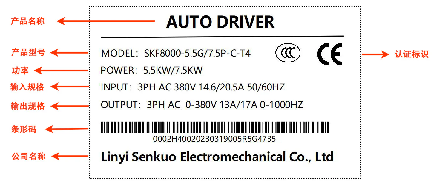
3.2 Product Nameplate
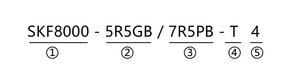
3.3 Model Description
| Field | Logo | Logo Description | Specific Content |
|---|---|---|---|
| Product series | ① | Product series | The general vector frequency converter series is 8000 |
| Rated power 1 | ② | G-type machine power range | 5R5-5.5KW, R is the decimal pointG-constant torque loadB-built-in brake unit |
| Rated power 2 | ③ | P-type machine power range | 7R5-7.5KW, R is the decimal pointP-variable torque loadB-built-in brake unit |
| Input power | ④ | Power phase number identification | S:single phase;T:three phase |
| Voltage level | ⑤ | Voltage level | 2:220VAC; 4: 380VAC |
3.4 Product Selection Specification Table
| Inverter model G/P | Rated power (kw) | Power capacity (KVA) | Input current(A) | Output current(A) | Adapted motor G/P(KW) | Adapted motor G/P(HP) |
|---|---|---|---|---|---|---|
| R75GB-S2 | 0.75 | 1.5 | 8.2 | 4.5 | 0.75 | 1 |
| 1R5GB-S2 | 1.5 | 3 | 14 | 7 | 1.5 | 2 |
| 2R2GB-S2 | 2.2 | 4 | 23 | 9.6 | 2.2 | 3 |
| R75GB-T4 | 0.75 | 1.5 | 3.4 | 2.1 | 0.75 | 1 |
| 1R5GB-T4 | 1.5 | 3 | 5.0 | 3.8 | 1.5 | 2 |
| 2R2GB-T4 | 2.2 | 4 | 5.8 | 5.1 | 2.2 | 3 |
| 004GB/5R5PB-T4 | 4/5.5 | 5.9/8.9 | 10.5/14.6 | 9/13 | 4/5.5 | 5.5/7.5 |
| 5R5GB/7R5PB-T4 | 5.5/7.5 | 8.9/11 | 14.6/20.5 | 13/17 | 5.5/7.5 | 7.5/10 |
| 7R5GB-T4 | 7.5 | 11 | 20.5 | 17 | 7.5 | 10 |
| 011GB/015PB-T4 | 11/15 | 17/21 | 26/35 | 25/32 | 11/15 | 15/20 |
| 015GB/18R5PB-T4 | 15/18.5 | 21/24 | 35/38.5 | 32/37 | 15/18.5 | 20/25 |
| 018R5GB/022PB-T4 | 18.5/22 | 24/30 | 38.5/46 | 37/45 | 18.5/22 | 25/30 |
| 022GB/030PB-T4 | 22/30 | 30/40 | 46.5/62 | 45/60 | 22/30 | 30/40 |
| 030G/037P-T4 | 30/37 | 40/57 | 62/76 | 60/75 | 30/37 | 40/50 |
| 037G/045P-T4 | 37/45 | 57/69 | 76/92 | 75/91 | 37/45 | 50/60 |
| 045G/055P-T4 | 45/55 | 69/85 | 92/113 | 91/110 | 45/55 | 60/70 |
| 055G/075P-T4 | 55/75 | 85/114 | 113/157 | 112/150 | 55/75 | 70/100 |
| 075G/093P-T4 | 75/93 | 114/134 | 157/180 | 150/170 | 75/93 | 100/125 |
| 093G/110P-T4 | 93/110 | 134/160 | 180/214 | 170/210 | 93/110 | 125/150 |
| 110G/132P-T4 | 110/132 | 160/192 | 214/256 | 210/253 | 110/132 | 150/180 |
| 132G/160P-T4 | 132/160 | 192/231 | 256/307 | 253/304 | 132/160 | 180/220 |
| 160G/185P-T4 | 160/185 | 231/245 | 307/345 | 304/340 | 160/185 | 220/250 |
| 185G/200P-T4 | 185/200 | 245/260 | 345/385 | 340/377 | 185/200 | 250/275 |
| 200G/220P-T4 | 200/220 | 260/280 | 385/430 | 377/426 | 200/220 | 275/300 |
| 220G/250P-T4 | 220/250 | 280/355 | 430/468 | 426/465 | 220/250 | 300/340 |
| 250G/280P-T4 | 250/280 | 355/396 | 468/525 | 465/520 | 250/280 | 340/380 |
| 280G/315P-T4 | 280/315 | 396/445 | 525/590 | 520/585 | 280/315 | 380/430 |
| 315G/355P-T4 | 315/355 | 445/500 | 590/665 | 585/650 | 315/355 | 430/480 |
| 355G/400P-T4 | 355/400 | 500/565 | 665/785 | 650/725 | 355/400 | 480/545 |
| 400G-T4 | 400 | 565 | 786 | 725 | 400 | 545 |
3.5 Keyboard Tray Dimension Drawing
| Inverter structure | C series tray opening size | H series tray opening size |
|---|---|---|
| Opening dimension drawing | 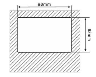 | 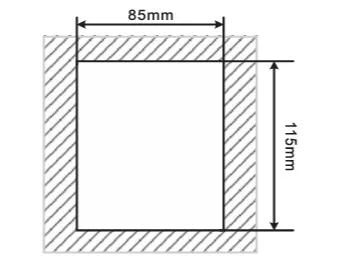 |
3.6 Daily Maintenance and Maintenance of Inverters
3.6.1 Daily Maintenance
Due to the influence of ambient temperature, humidity, dust and vibration, the internal components of the frequency converter will age, leading to potential failures of the frequency converter or reducing its service life. Therefore, it is necessary to carry out daily and regular maintenance and maintenance of the frequency converter.
Daily inspection items:
- Whether the sound of the motor changes abnormally during operation
- Whether the motor vibrates during operation
- Whether the installation environment of the frequency converter changes
- Whether the cooling fan of the frequency converter works normally
- Whether the frequency converter is overheated
Daily cleaning:
- The frequency converter should always be kept clean.
- Effectively remove dust on the surface of the frequency converter to prevent dust from entering the inside of the frequency converter. Especially metal dust.
- Effectively remove oil from the cooling fan of the frequency converter.
3.6.2 Regular Inspection
Please regularly check places that are difficult to check during operation.
Regular inspection items:
- Check the air duct and clean it regularly
- Check whether the screws are loose
- Check whether the frequency converter is corroded
- Check whether the wiring terminals have arc marks
- Main circuit insulation test Reminder: When measuring the insulation resistance with a megohmmeter (please use a DC 500V megohmmeter), the main circuit line should be disconnected from the frequency converter. Do not test the insulation of the control circuit with an insulation resistance meter. No high voltage test is required (completed at the factory).
3.6.3 Replacement of Vulnerable Parts of Inverters
The vulnerable parts of the frequency converter are mainly cooling fans and filtering electrolytic capacitors, and their service life is closely related to the use environment and maintenance conditions. The general service life is:
| Device name | Service life |
|---|---|
| Fan | 2~3 years |
| Electrolytic capacitor | 4~5 years |
Users can determine the replacement period according to the running time.
1)Cooling fan
Possible damage reasons: bearing wear, blade aging.
Judgment standard: whether there are cracks in the fan blades, whether there is abnormal vibration sound when starting.
2)Filter electrolytic capacitor
Possible damage reasons: poor input power quality, high ambient temperature, frequent load jumps, electrolyte aging.
Judgment standard: whether there is liquid leakage, whether the safety valve has protruded, measurement of electrostatic capacitance, measurement of insulation resistance.
3.6.4 Purchase of Inverters
After users purchase frequency converters, attention must be paid to the following points for temporary storage and long-term storage:
1)When storing, try to put it into our company’s packaging box according to the original packaging.
2)Long-term storage will lead to deterioration of electrolytic capacitors. It must be ensured that the power is turned on once within 2 years, and the power-on time is at least 5 hours. The input voltage must be slowly increased to the rated value with a voltage regulator.
3.7 Inverter Selection Guide
Frequency converters can provide three control methods: ordinary V/F, SVC, VC.
When selecting a frequency converter, you must first clarify the technical requirements of the system for variable frequency speed regulation, the application occasion of the frequency converter and the specific situation of the load characteristics, and comprehensively consider factors such as the adapted motor, output voltage, and rated output current, and then select a model that meets the requirements and determine the operation mode.
Basic principles:The rated load current of the motor cannot exceed the rated current of the frequency converter. Generally, select according to the motor capacity specified in the frequency converter manual, and pay attention to comparing the rated current of the motor and the frequency converter. The overload capacity of the frequency converter is only meaningful for the starting and braking process. Whenever there is a short-term overload during operation, it will cause a change in load speed. If the speed accuracy requirements are relatively high, please consider increasing one level.
Fan and pump type:It has low requirements for overload capacity. Because the load torque is proportional to the square of the speed, the load is lighter at low speed operation (except Roots blower). And because this type of load has no special requirements for speed accuracy, square torque V/F is selected.
Constant torque load:Most loads have constant torque characteristics, but generally have low requirements for speed accuracy and dynamic performance. For example, extruders, mixers, conveyors, factory transport trams, and the translation mechanism of cranes. When selecting a model, you can choose the multi-segment V/F operation mode.
The controlled object has certain dynamic and static index requirements:This type of load generally requires a harder mechanical characteristic at low speed to meet the dynamic and static index requirements of the production process for the control system. When selecting a model, you can choose the SVC control mode.
The controlled object has high dynamic and static index requirements:For occasions with high requirements for speed regulation accuracy and dynamic performance indicators and high-precision synchronous control, the VC control mode can be used. For example, elevators, papermaking, plastic film processing production lines.
3.8 Inverter Brake Component Selection Guide
3.8.1 Selection of Resistance Value
During braking, almost all the regenerative energy of the motor is consumed in the brake resistor.
According to the formula:U*U/R=Pb
●U in the formula—-Brake voltage for stable braking of the system
(Different systems are different, generally 700V for 380VAC system)
●Pb—-Brake power
3.8.2 Power Selection of Brake Resistance
Theoretically, the power of the brake resistance is consistent with the brake power, but considering derating to 70%
According to the formula:0.7Pr=PbD
●Pr—-Resistance power
●D—-Brake frequency (proportion of regeneration process in the entire working process)
Elevator—–20%-30%
Unwinding and winding—–20-30%
Centrifuge—–50%-60%
Accidental brake load-5%
Generally take 10%
3.8.3 Inverter Brake Component Selection Table
| Inverter power | Recommended power of brake resistance | Recommended resistance value of brake resistance | Brake unit | Remarks |
|---|---|---|---|---|
| 1.5KWT4 | 150w | ≥220Ω | Standard built-in | No special instructions |
| 2.2KWT4 | 250w | >200Ω | Standard built-in | No special instructions |
| 3.7KWT4 | 300W | ≥130Ω | Standard built-in | No special instructions |
| 5.5KWT4 | 400W | ≥90 Ω | Standard built-in | No special instructions |
| 7.5KWT4 | 500w | ≥65Ω | Standard built-in | No special instructions |
| 11KWT4 | 800w | ≥43Ω | Standard built-in | No special instructions |
| 15KWT4 | 1000w | ≥32Ω | Standard built-in | No special instructions |
| 18.5KWT4 | 1300w | ≥25Ω | Built-in optional | Add “B” after the inverter model |
| 22KWT4 | 1500w | ≥22Ω | Built-in optional | Add “B” after the inverter model |
| 30KWT4 | 2500w | ≥16Ω | Built-in optional | Add “B” after the inverter model |
| 37KWT4 | 3.7 kW | ≥16.0Ω | External | VFDBU-35-B |
| 45KWT4 | 4.5 kW | ≥16Ω | External | VFDBU-70-B |
| 55KWT4 | 5.5 kW | ≥8Ω | External | VFDBU-70-B |
| 75KWT4 | 7.5 kW | ≥8Ω | External | VFDBU-70-B×2 |
| 90KWT4 | 4.5 kW×2 | ≥8Ω×2 | External | VFDBU-70-B×2 |
| 110KWT4 | 5.5kW×2 | ≥8Ω×2 | External | VFDBU-70-B×2 |
| 132KWT4 | 6.5 kW×2 | ≥8Ω×2 | External | VFDBU-200-B |
| 160KWT4 | 16kW | ≥2.5Ω | External | VFDBU-200-B |
| 200KWT4 | 20 kW | ≥2.5Ω | External | VFDBU-200-B |
| 220KWT4 | 22 kW | ≥2.5Ω | External | VFDBU-200-B×2 |
| 250KWT4 | 12.5 kW×2 | ≥2.5Ω×2 | External | VFDBU-200-B×2 |
| 280KWT4 | 14kW×2 | ≥2.5Ω×2 | External | VFDBU-200-B×2 |
| 315KWT4 | 16kW×2 | ≥2.5Ω×2 | External | VFDBU-200-B×2 |
| 355KWT4 | 17kW×2 | ≥2.5Ω×2 | External | VFDBU-200-B×2 |
| 400KWT4 | 14kW×3 | ≥2.5Ω×3 | External | VFDBU-200-B×3 |
| 450KWT4 | 15kW×3 | ≥2.5Ω×3 | External | VFDBU-200-B×3 |
Note: ×2 means two brake units with their respective brake resistors are used in parallel, and ×3 has the same meaning as ×2.
Note
This selection table is a guide data, users can choose different resistance values and power according to the actual situation, (but the resistance value must not be less than the recommended value in the table, the power can be large.) The selection of brake resistance needs to be determined according to the power generated by the motor in the actual application system, which is related to system inertia, deceleration time, energy of potential energy load, etc., and needs to be selected by customers according to the actual situation. The greater the inertia of the system, the shorter the required deceleration time, and the more frequent the braking, the greater the power and smaller the resistance value of the brake resistance need to be selected.
4. Inverter Installation
4.1 Overall Structure Dimension Drawing
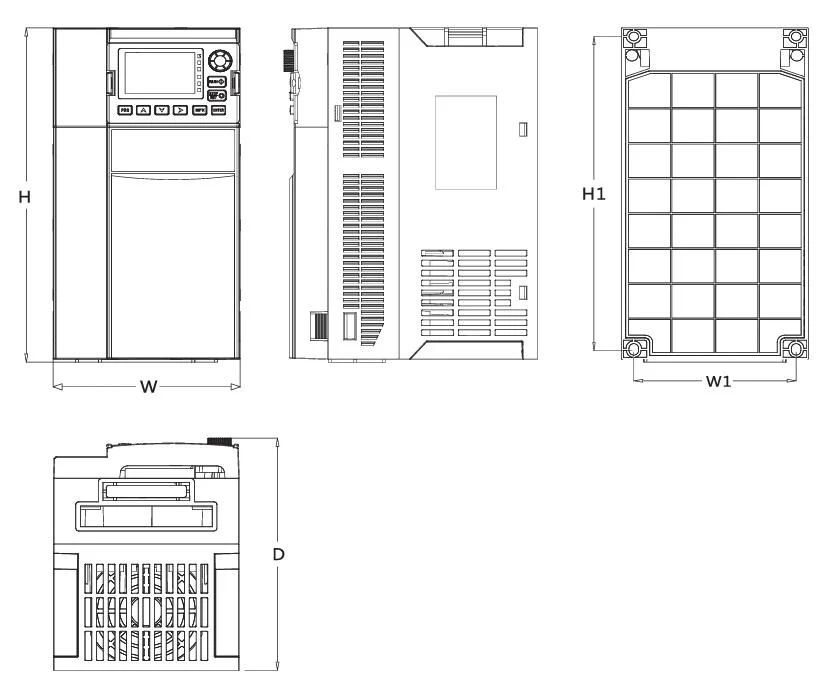
| Model | H(mm) | W(mm) | D(mm) | H1(mm) | W1(mm) | Hole opening d(mm) |
|---|---|---|---|---|---|---|
| R75GB-S2 | 197.2 | 89.6 | 139 | 187 | 74 | 5 |
| 1R5GB-S2 | 197.2 | 89.6 | 139 | 187 | 74 | 5 |
| 2R2GB-S2 | 197.2 | 89.6 | 139 | 187 | 74 | 5 |
| R75GB-T4 | 197.2 | 89.6 | 139 | 187 | 74 | 5 |
| 1R5GB-T4 | 197.2 | 89.6 | 139 | 187 | 74 | 5 |
| 2R2GB-T4 | 197.2 | 89.6 | 139 | 187 | 74 | 5 |
| 004GB/5R5PB-T4 | 202 | 102 | 162 | 190.5 | 90 | 5 |
| 5R5GB/7R5PB-T4 | 202 | 102 | 162 | 190.5 | 90 | 5 |
| 7R5GB-T4 | 242.5 | 125 | 170 | 228 | 108.5 | 5 |
| 011GB/015PB-T4 | 242.5 | 125 | 170 | 228 | 108.5 | 5 |
| 015GB/18R5PB-T4 | 297 | 165 | 206 | 278 | 147 | 6 |
| 018R5GB/022PB-T4 | 297 | 165 | 206 | 278 | 147 | 6 |
| 022GB/030PB-T4 | 360 | 210 | 190 | 345 | 110 | 7 |
| 030G/037P-T4 | 435 | 230 | 230 | 418 | 150 | 7 |
| 037G/045P-T4 | 435 | 230 | 230 | 418 | 150 | 7 |
| 045G/055P-T4 | 510 | 260 | 255 | 200 | 493 | 7 |
| 055G/075P-T4 | 580 | 270 | 300 | 564 | 200 | 7 |
| 075G/093P-T4 | 580 | 270 | 300 | 564 | 200 | 7 |
| 093G/110P-T4 | 620 | 320 | 300 | 600 | 260 | 9 |
| 110G/132P-T4 | 620 | 320 | 300 | 600 | 260 | 9 |
| 132G/160P-T4 | 800 | 380 | 315 | 775 | 260 | 10 |
| 160G/185P-T4 | 800 | 380 | 315 | 775 | 260 | 10 |
| 185G/200P-T4 | 800 | 400 | 345 | 755 | 250 | 12 |
| 200G/220P-T4 | 900 | 450 | 350 | 875 | 350 | 12 |
| 220G/250P-T4 | 900 | 450 | 350 | 875 | 350 | 12 |
| 250G/280P-T4 | 900 | 450 | 350 | 875 | 350 | 12 |
| 280G/315P-T4 | 950 | 500 | 350 | 925 | 360 | 12 |
| 315G/355P-T4 | 1050 | 650 | 360 | 1029 | 500 | 12 |
| 355G/400P-T4 | 1050 | 650 | 360 | 1029 | 500 | 12 |
| 400G/450P-T4 | 1300 | 650 | 380 | 1265 | 500 | 12 |
| 450G/500P-T4 | 1300 | 650 | 380 | 1265 | 500 | 12 |
| 500G/560P-T4 | 1300 | 650 | 380 | 1265 | 500 | 12 |
| 560G/630P-T4 | 1500 | 800 | 400 | 1450 | 550 | 14 |
| 630G/720P-T4 | 1500 | 800 | 400 | 1450 | 550 | 14 |
| 720G/800P-T4 | 1500 | 800 | 400 | 1450 | 550 | 14 |
4.2 Main Circuit Terminal and Function
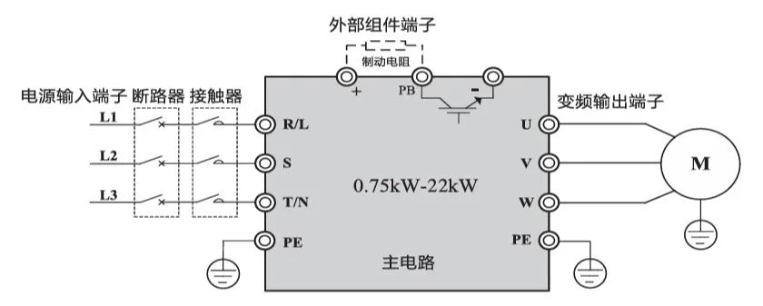
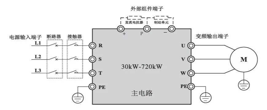
| Terminal mark | Name | Description |
|---|---|---|
| R、S、T | Three-phase power input terminal | Three-phase AC power input connection terminal |
| (+)、(-) | DC bus positive and negative terminals | Common DC bus input terminal (connection terminal of external brake unit above 30KW) |
| (+)、PB | Brake resistor connection terminal | 22KW and above brake resistor connection terminal |
| P、(+) | External reactor connection terminal | External DC reactor connection terminal |
| ⏚ | Grounding terminal | Connect to the earth |
4.3 Control Circuit Terminal and Function
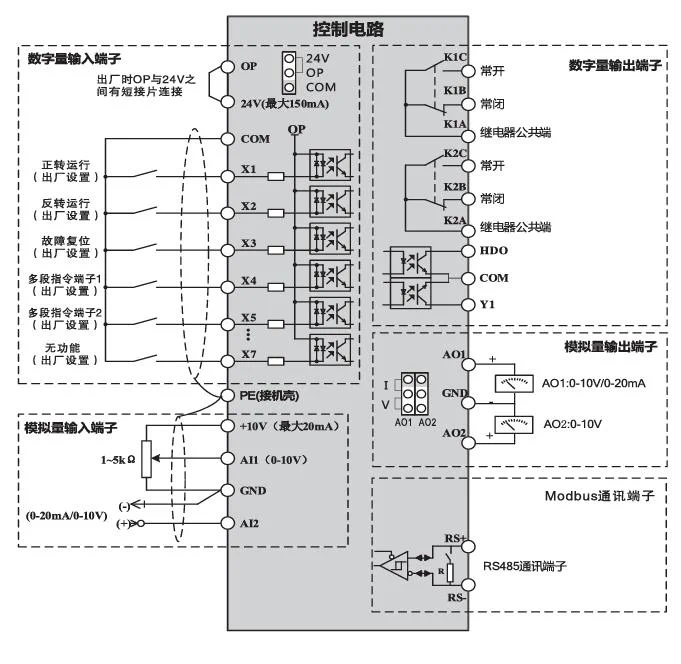
4.4 Control Terminal and Function
| Category | Terminal symbol | Terminal name | Function description |
|---|---|---|---|
| Power | +10V-GND | +10V power | Provide +10V power supply externally, maximum output current: 20mA, generally used as external potentiometer working power supply |
| Power | +24V-COM | +24V power | Provide +24V power supply externally, maximum output current: 150mA, generally used as working power supply for digital input and output terminals and external sensor power supply |
| Power | OP | External power input terminal | Select to connect with +24V or COM through the connection piece on the control board (default connected to +24V at the factory)When using external signal to drive DI1-DI6, OP needs to be connected to external power supply, and remove the short connection piece between OP-24V terminals here |
| Analog input | AI1-GND | Analog input terminal 1 | 1、Input range:DC0V~10V/0mA,selected by parameter P4-37 for voltage or current input.2、Input impedance:voltage input 22kΩ,current input 500Ω |
| Analog input | AI2-GND | Analog input terminal 2 | 1、Input range:DC0V~10V/0mA,selected by parameter P4-37 for voltage or current input.2、Input impedance:voltage input 22kΩ,current input 500Ω |
| Digital input | X1 、X2、X3、X4、X5、X6、X7 | Digital input 1、2、3、4、5、6、7 | 1、Optocoupler isolation2、Input impedance:4kΩVoltage range for level input:9V-30V |
| Analog output | AO1-GND | Analog output 1 | AO1, AO2 select voltage or current output by jumper on the control boardOutput voltage range:0V-10VOutput current range:0mA-20mADefault voltage output at factory |
| Analog output | AO2-GND(shared with Y1 for motors below 18.5KW, output selected by jumper) | Analog output 2 | AO1, AO2 select voltage or current output by jumper on the control boardOutput voltage range:0V-10VOutput current range:0mA-20mADefault voltage output at factory |
| Digital output | HD0 | High-speed pulse output open collector output | 1、Optocoupler isolation, bipolar open collector output.2、Output voltage range:0V-24VOutput current range:0mA-50mA(Note:Y1 function can be switched to analog output via jumper for motors below 18.5KW) |
| Digital output | Y1 | Digital output 1Analog voltage output 2 | 1、Optocoupler isolation, bipolar open collector output.2、Output voltage range:0V-24VOutput current range:0mA-50mA(Note:Y1 function can be switched to analog output via jumper for motors below 18.5KW) |
| Relay output | K1A-K1BK2A-K2B | Normally closed terminal | Contact driving capacity:AC 250V, 3A;DC 30V ,1A |
| Relay output | K1A-K1CK2A-K2C | Normally open terminal | Contact driving capacity:AC 250V, 3A;DC 30V ,1A |
| RS485 communication | RS+ | 485 communication terminal positive | RS485 differential signal positive terminal |
| RS485 communication | RS- | 485 communication terminal negative | RS485 differential signal negative terminal |
4.5 Mechanical Installation
4.5.1 Installation Environment:
Ambient temperature:The ambient temperature around the frequency converter has a great influence on its service life. The operating ambient temperature of the frequency converter is not allowed to exceed the allowable temperature range (-10℃~50℃).
Install the frequency converter on the surface of flame-retardant objects, with enough space around for heat dissipation. The frequency converter is easy to generate a lot of heat during work. And install it vertically on the mounting support with screws.
Please install it in a place not prone to vibration. The vibration should not be greater than 0.6G. Pay special attention to stay away from equipment such as punch presses.
Avoid installation in places exposed to direct sunlight, humidity, or water droplets.
Avoid installation in places with corrosive, flammable, or explosive gases in the air.
Avoid installation in places with oil, dust, or metal dust.
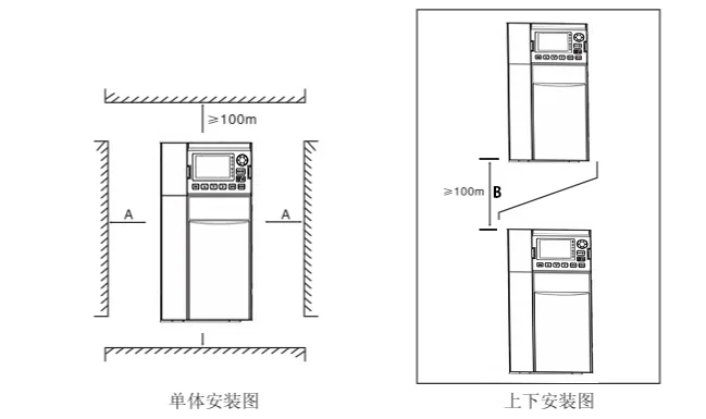
When installing individually: When the inverter power is not greater than 22kW, the A dimension may not be considered. When greater than 22kW, A should be greater than 50mm. When installing up and down: When installing the inverter up and down, please install the heat insulation deflector as shown in the figure.
| Inverter power | Installation dimension A | Installation dimension B |
|---|---|---|
| ≤15kW | No requirement | ≥100mm |
| 18.5kW—30kW | ≥50mm | ≥200mm |
| ≥37kW | ≥50mm | ≥300mm |
4.5.2 Mechanical Installation Notes
The key issue for mechanical installation is heat dissipation. So please note the following points:
Please install the frequency converter vertically to facilitate heat dissipation upward. But it cannot be inverted. If there are multiple frequency converters in the cabinet, it is best to install them side by side. In the case of upper and lower installation, please refer to the installation diagram to install the heat insulation deflector.
Follow the installation diagram to ensure the heat dissipation space of the frequency converter. But when arranging, please consider the heat dissipation of other devices in the cabinet.
The installation bracket must be flame retardant material.
For applications with metal dust, it is recommended to use the radiator external installation method. At this time, the fully sealed cabinet space should be as large as possible.
4.6 Inverter Peripheral Electrical Component Selection Guide
| Inverter power | Air switch(MCCB)A | Recommended contactorA | Recommended input side main circuit wire mm² | Recommended output side main circuit wire mm² | Recommended control circuit wire mm² |
|---|---|---|---|---|---|
| 0.4KWT2 | 16 | 10 | 2.5 | 2.5 | 1.0 |
| 0.7KWT2 | 16 | 10 | 2.5 | 2.5 | 1.0 |
| 1.5KWT2 | 20 | 16 | 4.0 | 2.5 | 1.0 |
| 2.2KWT2 | 32 | 20 | 6.0 | 4.0 | 1.0 |
| 0.7KWT4 | 10 | 10 | 2.5 | 2.5 | 1.0 |
| 1.5KWT4 | 16 | 10 | 2.5 | 2.5 | 1.0 |
| 2.2KWT4 | 16 | 10 | 2.5 | 2.5 | 1.0 |
| 3.7KWT4 | 25 | 16 | 4.0 | 4.0 | 1.0 |
| 5.5KWT4 | 32 | 25 | 4.0 | 4.0 | 1.0 |
| 7.5KWT4 | 40 | 32 | 4.0 | 4.0 | 1.0 |
| 11KWT4 | 63 | 40 | 4.0 | 4.0 | 1.0 |
| 15KWT4 | 63 | 40 | 6.0 | 6.0 | 1.0 |
| 18.5KWT4 | 100 | 63 | 6 | 6 | 1.5 |
| 22KWT4 | 100 | 63 | 10 | 10 | 1.5 |
| 30KWT4 | 125 | 100 | 16 | 10 | 1.5 |
| 37KWT4 | 160 | 100 | 16 | 16 | 1.5 |
| 45KWT4 | 200 | 125 | 25 | 25 | 1.5 |
| 55KWT4 | 200 | 125 | 35 | 25 | 1.5 |
| 75KWT4 | 250 | 160 | 50 | 35 | 1.5 |
| 90KWT4 | 250 | 160 | 70 | 35 | 1.5 |
| 110KWT4 | 350 | 350 | 120 | 120 | 1.5 |
| 132KWT4 | 400 | 400 | 150 | 150 | 1.5 |
| 160KWT4 | 500 | 400 | 185 | 185 | 1.5 |
| 200KWT4 | 600 | 600 | 150*2 | 150*2 | 1.5 |
| 220KWT4 | 600 | 600 | 150*2 | 150*2 | 1.5 |
| 250KWT4 | 800 | 600 | 185*2 | 185*2 | 1.5 |
| 280KWT4 | 800 | 800 | 185*2 | 185*2 | 1.5 |
| 315KWT4 | 800 | 800 | 150*3 | 150*3 | 1.5 |
| 355KWT4 | 800 | 800 | 150*4 | 150*4 | 1.5 |
| 400KWT4 | 1000 | 1000 | 150*4 | 150*4 | 1.5 |
Note
This selection table is a guide data, users can choose different sizes of electrical components according to the actual situation, but not less than the recommended values in the table.
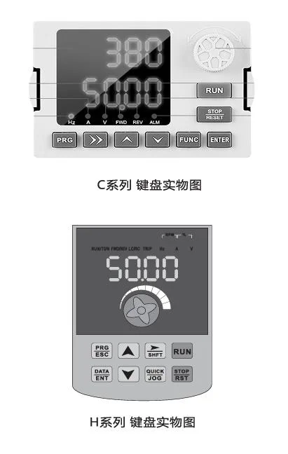
5. Panel Display and Operation
5.1 Display Interface Introduction
Using the operation panel, you can modify the functional parameters of the frequency converter, monitor the working status of the frequency converter, and start and stop the frequency converter, etc. Its appearance and functional areas are shown in the following figure:
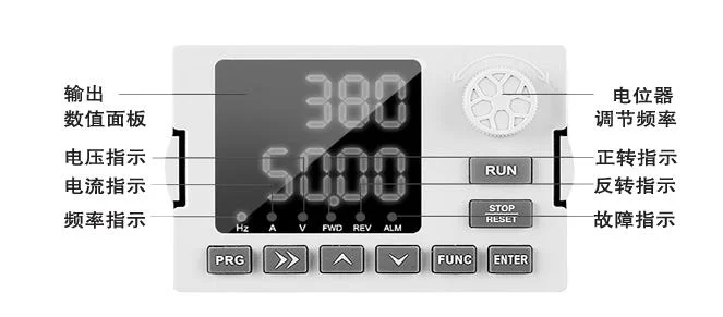
C Series Inverter Operation Panel Indicator Lights and Button Functions
| Button symbol | Name | Function description |
|---|---|---|
| PRG | Programming key | Menu entry or exit, parameter modification |
| ENTER | Confirm key | Select parameter modification shift and display content |
| 🔼 | Increment key | Increment of data or function code |
| 🔽 | Decrement key | Decrement of data or function code |
| ▶️ | Shift key | According to function switch selection |
| RUN | Run key | Enter menu, confirm parameter setting |
| STOP/RESET | Stop/reset key | Run operation under keyboard operation mode |
| FUNC | Multi-function shortcut key | Jog |
| REV | Indicator light | Inverter reverse indicator, the light is on when in reverse operation state |
| FWD | Indicator light | Inverter forward indicator, the light is on when in forward operation state |
| ALM | Indicator light | Inverter fault indicator, the light is on when in fault state |
| Hz | Indicator light | Frequency unit |
| A | Indicator light | Current unit |
| V | Indicator light | Voltage unit |
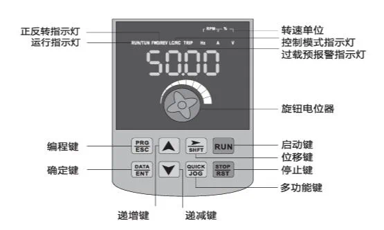
H Series Inverter Operation Panel Indicator Lights and Button Functions
| Name | Function description |
|---|---|
| Unit indicator light | Hz:frequency unit;A:current unit;V:voltage unit;RMP(Hz+A):speed unit;%(A+V) :percentage |
| Status indicator light | RUN:on/running;off/stopped;FWD/REV:on/forward;off/reverse;flashing/forward and reverse switching;TUNE/TC:slow flash/tuning state;fast flash/communication state;slow flash about 1 time/second;fast flash about 2 times/secondLOCAL/REMOTE:on/terminal control;flashing/communication control;off/keyboard control. |
| PRG(Programming key) | First level menu entry or exit |
| ENTER(Confirm key) | Enter menu screen level by level, confirm parameter setting |
| 🔼(Increment key) | Increment of data or function code |
| 🔽(Decrement key) | Decrement of data or function code |
| ▶️ (Shift key) | In stop display interface and running display interface, you can cycle to select display parameters;when modifying parameters, you can select the modification bit of parameters. |
| RUN(Run key) | Used for run operation in keyboard operation mode. |
| STOP/RESET(Stop/reset key) | When in running state, press this key to stop running operation;when in fault alarm state, it can be used for reset operation, the characteristics of this key are restricted by function code F7.02. |
| MF.K(Multi-function shortcut key) | Switch selection according to F7.01 function. |
| Knob(Pulse potentiometer) | Can be used as frequency given source. When the frequency converter is set to use this knob as the frequency source, clockwise rotation increases the given, counterclockwise rotation decreases the given. |
Inverter Function Code Viewing and Modification Method Description
The operation panel of the frequency converter adopts a three-level menu structure for parameter setting and other operations. The three-level menus are: functional parameter level (first-level menu) → function code (second-level menu) → function code setting value (third-level menu). The operation flow is shown in the following figure:
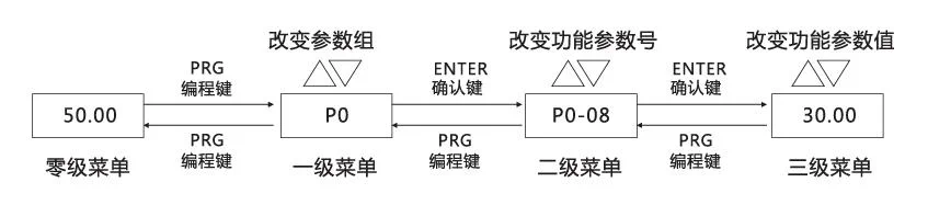
Note: In the third-level menu operation, you can press the PRG (programming) key or ENTER(confirm) key to return to the second-level menu. The difference between them is: pressing the ENTER(confirm) key will save the set parameters and return to the second-level menu, and automatically transfer to the next function code; while pressing the PRG(programming) key will directly return to the second-level menu without storing parameters, and return to the current function code.
Example: Example of changing function code P3-02 from 10.00Hz to 15.00Hz. (Bold text indicates flashing bit)
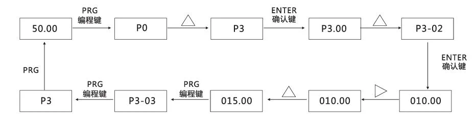
In the third-level menu state, if the parameter has no flashing bit, it means that this function code cannot be modified. The possible reasons are:
- This function code is a non-modifiable parameter. Such as actual detection parameters, operation record parameters.
- This function code cannot be modified in running state, and needs to be modified after stopping.
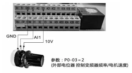
5.2 Inverter Terminal Application Wiring Diagram
0.75~37KW Inverter Wiring Diagram
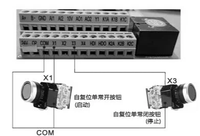
Description: Press the green button, the frequency converter starts; press the red stop button, the frequency converter stops;
Inverter parameter setting: P0-02=1;P4-02=3;P4-11=2
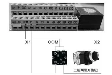
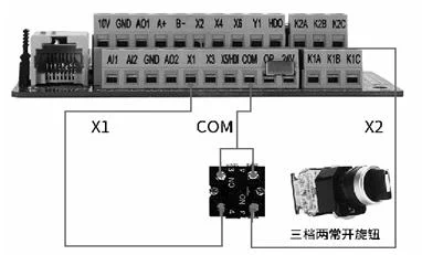
Description: Three-speed two normally open knob, turn to the left to rotate the motor forward, turn to the middle to stop the motor, turn to the right to rotate the motor reverse.
Inverter parameter setting: P0-02=1
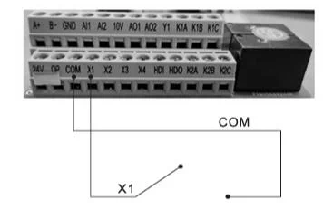
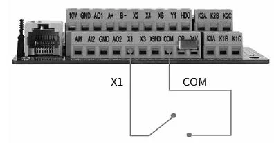
Description: When X1 terminal and COM terminal are connected, the frequency converter starts; when X1 terminal and COM terminal are disconnected, the frequency converter stops; start directly when power on, stop when power off, directly short COM and X1.
Inverter parameter setting: P0-02=1
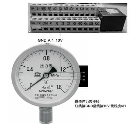
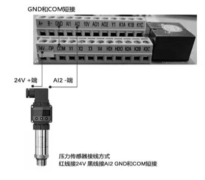
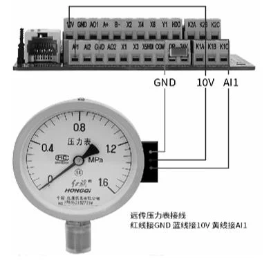
Description: As the core of the water supply system, the frequency converter can monitor water pressure changes in real time and intelligently adjust the speed of the water pump according to demand. When multiple users use water at the same time, the frequency converter will automatically increase the output power of the water pump to maintain stable water pressure; when using a smaller water flow, the frequency converter will reduce the output power of the water pump to avoid excessive water pressure.
Inverter parameter setting: P0-29=00001, b0-00=pressure gauge range, b0-01=set pressure, b0-02=sleep pressure, b0-03=wake-up pressure;
Example: If the remote pressure gauge range is 1MPA, b0-00=10, if the range is 1.6MPA, b0-00=16.
The upper row displays the set pressure, and the lower row displays the pressure gauge feedback pressure. Change the set pressure by adjusting the panel increase 🔼/decrease 🔽 keys, and the display pressure unit is kg. The upper row can switch to display bus voltage, current, frequency, set pressure, and feedback pressure through the ▶️ key.
🌟Note 1: The above settings default to external terminal operation after P0-29=00001. If panel startup is required, set P0-02=0.
🌟Note 2: The settings of b0-02 and b0-03 are relative to the percentage of b0-01.
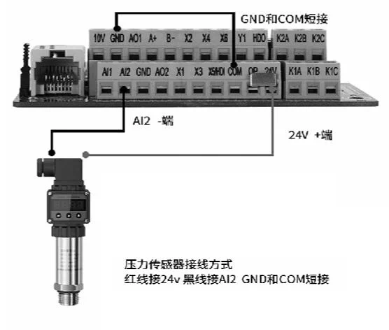
 Description: As the core of the constant pressure water supply system, the frequency converter can monitor water pressure changes in real time and intelligently adjust the speed of the water pump according to demand. When multiple users use water at the same time, the frequency converter will automatically increase the output power of the water pump to maintain stable water pressure; when using a smaller water flow, the frequency converter will reduce the output power of the water pump to avoid excessive water pressure.
Inverter parameter settings: P0-29=00001, b0-00=pressure transmitter range, b0-01=set pressure, b0-02=sleep pressure, b0-03=wake-up pressure;
Example: If the pressure transmitter range is 1MPA, b0-00=10, if the range is 1.6MPA, b0-00=16.
The upper row displays the set pressure, and the lower row displays the pressure transmitter feedback pressure. Change the set pressure by adjusting the panel increase 🔼/decrease 🔽 keys, and the display pressure unit is kg. The upper row can switch to display bus voltage, current, frequency, set pressure, and feedback pressure through the ▶️ key.
🌟Note 1: The above settings default to external terminal operation after P0-29=00001. If panel startup is required, set P0-02=0.
🌟Note 2: The settings of b0-02 and b0-03 are relative to the percentage of b0-01.
Description: As the core of the constant pressure water supply system, the frequency converter can monitor water pressure changes in real time and intelligently adjust the speed of the water pump according to demand. When multiple users use water at the same time, the frequency converter will automatically increase the output power of the water pump to maintain stable water pressure; when using a smaller water flow, the frequency converter will reduce the output power of the water pump to avoid excessive water pressure.
Inverter parameter settings: P0-29=00001, b0-00=pressure transmitter range, b0-01=set pressure, b0-02=sleep pressure, b0-03=wake-up pressure;
Example: If the pressure transmitter range is 1MPA, b0-00=10, if the range is 1.6MPA, b0-00=16.
The upper row displays the set pressure, and the lower row displays the pressure transmitter feedback pressure. Change the set pressure by adjusting the panel increase 🔼/decrease 🔽 keys, and the display pressure unit is kg. The upper row can switch to display bus voltage, current, frequency, set pressure, and feedback pressure through the ▶️ key.
🌟Note 1: The above settings default to external terminal operation after P0-29=00001. If panel startup is required, set P0-02=0.
🌟Note 2: The settings of b0-02 and b0-03 are relative to the percentage of b0-01.
45~720KW Inverter Wiring Diagram
 Description: Press the green button, the frequency converter starts; press the red stop button, the frequency converter stops;
Inverter parameter settings: P0-02=1;P4-02=3;P4-11=2
Description: Press the green button, the frequency converter starts; press the red stop button, the frequency converter stops;
Inverter parameter settings: P0-02=1;P4-02=3;P4-11=2
 Description: Three-speed two normally open knob, turn to the left to rotate the motor forward, turn to the middle to stop the motor, turn to the right to rotate the motor reverse.
Inverter parameter settings: P0-02=1
Description: Three-speed two normally open knob, turn to the left to rotate the motor forward, turn to the middle to stop the motor, turn to the right to rotate the motor reverse.
Inverter parameter settings: P0-02=1
 Description: When X1 terminal and COM terminal are connected, the frequency converter starts; when X1 terminal and COM terminal are disconnected, the frequency converter stops; start directly when power on, stop when power off, directly short COM and X1.
Inverter parameter settings: P0-02=1
Description: When X1 terminal and COM terminal are connected, the frequency converter starts; when X1 terminal and COM terminal are disconnected, the frequency converter stops; start directly when power on, stop when power off, directly short COM and X1.
Inverter parameter settings: P0-02=1
 Description: As the core of the constant pressure water supply system, the frequency converter can monitor water pressure changes in real time and intelligently adjust the speed of the water pump according to demand. When multiple users use water at the same time, the frequency converter will automatically increase the output power of the water pump to maintain stable water pressure; when using a smaller water flow, the frequency converter will reduce the output power of the water pump to avoid excessive water pressure.
Inverter parameter settings: P0-29=00001, b0-00=pressure gauge range, b0-01=set pressure, b0-02=sleep pressure, b0-03=wake-up pressure;
Example: If the remote pressure gauge range is 1MPA, b0-00=10, if the range is 1.6MPA, b0-00=16.
The upper row displays the set pressure, and the lower row displays the pressure gauge feedback pressure. Change the set pressure by adjusting the panel increase 🔼/decrease 🔽 keys, and the display pressure unit is kg. The upper row can switch to display bus voltage, current, frequency, set pressure, and feedback pressure through the ▶️ key.
🌟Note 1: The above settings default to external terminal operation after P0-29=00001. If panel startup is required, set P0-02=0.
🌟Note 2: The settings of b0-02 and b0-03 are relative to the percentage of b0-01.
Description: As the core of the constant pressure water supply system, the frequency converter can monitor water pressure changes in real time and intelligently adjust the speed of the water pump according to demand. When multiple users use water at the same time, the frequency converter will automatically increase the output power of the water pump to maintain stable water pressure; when using a smaller water flow, the frequency converter will reduce the output power of the water pump to avoid excessive water pressure.
Inverter parameter settings: P0-29=00001, b0-00=pressure gauge range, b0-01=set pressure, b0-02=sleep pressure, b0-03=wake-up pressure;
Example: If the remote pressure gauge range is 1MPA, b0-00=10, if the range is 1.6MPA, b0-00=16.
The upper row displays the set pressure, and the lower row displays the pressure gauge feedback pressure. Change the set pressure by adjusting the panel increase 🔼/decrease 🔽 keys, and the display pressure unit is kg. The upper row can switch to display bus voltage, current, frequency, set pressure, and feedback pressure through the ▶️ key.
🌟Note 1: The above settings default to external terminal operation after P0-29=00001. If panel startup is required, set P0-02=0.
🌟Note 2: The settings of b0-02 and b0-03 are relative to the percentage of b0-01.
 Description: As the core of the water supply system, the frequency converter can monitor water pressure changes in real time and intelligently adjust the speed of the water pump according to demand. When multiple users use water at the same time, the frequency converter will automatically increase the output power of the water pump to maintain stable water pressure; when using a smaller water flow, the frequency converter will reduce the output power of the water pump to avoid excessive water pressure.
Inverter parameter settings: P0-29=00001, b0-00=pressure transmitter range, b0-01=set pressure, b0-02=sleep pressure, b0-03=wake-up pressure;
Example: If the pressure transmitter range is 1MPA, b0-00=10, if the range is 1.6MPA, b0-00=16.
The upper row displays the set pressure, and the lower row displays the pressure transmitter feedback pressure. Change the set pressure by adjusting the panel increase 🔼/decrease 🔽 keys, and the display pressure unit is kg. The upper row can switch to display bus voltage, current, frequency, set pressure, and feedback pressure through the ▶️ key.
🌟Note 1: The above settings default to external terminal operation after P0-29=00001. If panel startup is required, set P0-02=0.
🌟Note 2: The settings of b0-02 and b0-03 are relative to the percentage of b0-01.
Description: As the core of the water supply system, the frequency converter can monitor water pressure changes in real time and intelligently adjust the speed of the water pump according to demand. When multiple users use water at the same time, the frequency converter will automatically increase the output power of the water pump to maintain stable water pressure; when using a smaller water flow, the frequency converter will reduce the output power of the water pump to avoid excessive water pressure.
Inverter parameter settings: P0-29=00001, b0-00=pressure transmitter range, b0-01=set pressure, b0-02=sleep pressure, b0-03=wake-up pressure;
Example: If the pressure transmitter range is 1MPA, b0-00=10, if the range is 1.6MPA, b0-00=16.
The upper row displays the set pressure, and the lower row displays the pressure transmitter feedback pressure. Change the set pressure by adjusting the panel increase 🔼/decrease 🔽 keys, and the display pressure unit is kg. The upper row can switch to display bus voltage, current, frequency, set pressure, and feedback pressure through the ▶️ key.
🌟Note 1: The above settings default to external terminal operation after P0-29=00001. If panel startup is required, set P0-02=0.
🌟Note 2: The settings of b0-02 and b0-03 are relative to the percentage of b0-01.
General Inverter Multi-speed Command Function Description
4 multi-speed command terminals can be combined into 16 states, and these 16 states correspond to 16 command setting values. The details are shown in the following table:
| K4 | K3 | K2 | K1 | Command setting | Corresponding parameter |
|---|---|---|---|---|---|
| OFF | OFF | OFF | OFF | Multi-stage designation 0 | PC-00 |
| OFF | OFF | OFF | ON | Multi-stage designation 1 | PC-01 |
| OFF | OFF | ON | OFF | Multi-stage designation 2 | PC-02 |
| OFF | OFF | ON | ON | Multi-stage designation 3 | PC-03 |
| OFF | ON | OFF | OFF | Multi-stage designation 4 | PC-04 |
| OFF | ON | OFF | ON | Multi-stage designation 5 | PC-05 |
| OFF | ON | OFF | ON | Multi-stage designation 6 | PC-06 |
| OFF | ON | ON | ON | Multi-stage designation 7 | PC-07 |
| ON | OFF | OFF | OFF | Multi-stage designation 8 | PC-08 |
| ON | OFF | OFF | ON | Multi-stage designation 9 | PC-09 |
| ON | OFF | ON | OFF | Multi-stage designation 10 | PC-10 |
| ON | OFF | ON | ON | Multi-stage designation 11 | PC-11 |
| ON | ON | OFF | OFF | Multi-stage designation 12 | PC-12 |
| ON | ON | OFF | ON | Multi-stage designation 13 | PC-13 |
| ON | ON | ON | OFF | Multi-stage designation 14 | PC-14 |
| ON | ON | ON | ON | Multi-stage designation 15 | PC-15 |
When the frequency source is selected as multi-speed, 100% of the function codes PC-00~PC-15 corresponds to PC-10 (maximum frequency)
6. Inverter Function Parameter Table
✅: Indicates that the setting value of this parameter can be changed when the frequency converter is in shutdown or running state; ✳️: Indicates that the setting value of this parameter cannot be changed when the frequency converter is in running state; ❎: Indicates that the value of this parameter is an actual detection record value and cannot be changed;
P0 Group: Basic Parameters
| Function code | Name | Setting range | Factory value | Attribute | DEC address |
|---|---|---|---|---|---|
| P0-00 | G/P machine type | 1:G type2:P type | 1 | ✳️ | 61440 |
| P0-01 | Motor control mode | 0:Sensorless vector control2:V/F control | 2 | ✳️ | 61441 |
| P0-02 | Command source selection | 0:Panel command channel (LED off)1:Terminal command channel (LED on)2:Communication command channel (LED flashing) | 0 | ✅ | 61442 |
| P0-03 | Main frequency source X selection | 0:Digital setting (preset frequency P0-08, UP/DOWN can be modified, power-off does not remember)1:Digital setting (preset frequency P0-08, UP/DOWN can be modified, power-off remembers)2:AI13:AI24:AI3 keyboard potentiometer5:HDI pulse setting (X5)6:Multi-stage command7:Simple PLC8:PID9:Communication given | 4 | ✳️ | 61443 |
| P0-04 | Frequency source Y selection | Same as P0-03 (main frequency source X selection) | 0 | ✳️ | 61444 |
| P0-05 | Frequency source Y selection range when superimposed | 0:Relative to maximum frequency1:Relative to frequency source X | 0 | ✅ | 61445 |
| P0-06 | Frequency source Y range when superimposed | 0%~150% | 100% | ✅ | 61446 |
| P0-07 | Frequency source superposition mode selection | Units digit:Frequency source selection0:Main frequency source X1:Main and auxiliary operation (operation mode determined by tens digit)2:Main frequency source X and auxiliary frequency source Y switching3:Main frequency source X and main and auxiliary operation result switching4:Auxiliary frequency source Y and main and auxiliary operation result switchingTens digit:Main and auxiliary operation relationship of frequency source0:Main + auxiliary1:Main - auxiliary2:Maximum of both3:Minimum of both4:Main * auxiliary | 00 | ✅ | 61447 |
| P0-08 | Preset frequency | 0.00Hz~maximum frequency (P0-10) | 50Hz | ✅ | 61448 |
| P0-09 | Running direction | 0:Same direction1:Opposite direction | 0 | ✅ | 61449 |
| P0-10 | Maximum frequency | 50.00Hz | 50.00Hz50.0Hz | ✳️ | 61450 |
| P0-11 | Upper limit frequency source | 0:P0-12 setting1:AI12:AI23:AI3 external keyboard potentiometer4:HDI pulse setting5:Communication given | 0 | ✳️ | 61451 |
| P0-12 | Upper limit frequency | Lower limit frequency P0-14~maximum frequency P0-10 | 50.00Hz | ✅ | 61452 |
| P0-13 | Upper limit frequency offset | 0.00Hz~maximum frequency (P0-10) | 0.00Hz | ✅ | 61453 |
| P0-14 | Lower limit frequency | 0.00Hz~upper limit frequency (P0-12) | 0.00Hz | ✅ | 61454 |
| P0-15 | Carrier frequency | 0.5kHz~16.0kHz | Machine type determined | ✅ | 61455 |
| P0-16 | Carrier frequency adjustment with temperature | 0:No1:Yes | 0 | ✅ | 61456 |
| P0-17 | Acceleration time 1 | 0s | Machine type determined | ✅ | 61457 |
| P0-18 | Deceleration time 1 | Same as above | Machine type determined | ✅ | 61458 |
| P0-19 | Acceleration/deceleration time unit | 0:1 second1:0.1 second2:0.01 second | 1 | ✳️ | 61459 |
| P0-21 | Offset frequency of auxiliary frequency source when superimposed | 0.00Hz~maximum frequency (P0-10) | 0.00Hz | ✅ | 61461 |
| P0-22 | Frequency specified resolution | 1:0.1Hz2:0.01HzNote: Changing to 1 can achieve high frequency output | 2 | ✳️ | 61462 |
| P0-23 | Digital setting frequency shutdown memory | 0:Do not remember1:Remember | 0 | ✅ | 61463 |
| P0-24 | Reserved | - | 0 | ✅ | 61464 |
| P0-25 | Acceleration/deceleration time reference frequency | 0:Maximum frequency P0-101:Setting frequency | 0 | ✳️ | 61465 |
| P0-26 | Running frequency command UP/DOWN reference | 0:Running frequency1:Setting frequency | 1 | ✳️ | 61466 |
| P0-27 | Command source bundling frequency source | Units digit:Operation panel command binding frequency source selection0:No binding1:Digital setting frequency2:AI13:AI24:AI3 external keyboard potentiometer5:HDI pulse setting (X5)6:Multi-speed7:Simple PLC8:PID9:Communication givenTens digit:Terminal command binding frequency source selectionHundreds digit:Communication command binding frequency source selectionThousands digit:Automatic operation binding frequency source selection | 0000 | ✅ | 61467 |
| P0-28 | Reserved | ||||
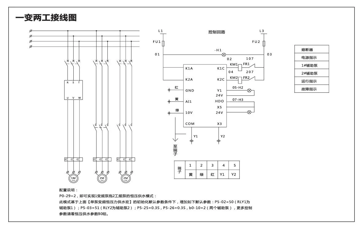
| P0-29 | Application macro | Setting range:0~6553510000:Function code restore factory setting macro1:Frequency conversion single pump constant pressure water supply macro2:One drag three constant pressure water supply macro (1 variable 2 power frequency)3:One drag five constant pressure water supply macro (1 variable 4 power frequency)7:Fire inspection water supply macro11:CNC machine tool 100Hz macro 112:CNC machine tool 100Hz macro 221:Spindle engraving 400Hz macro 122:Spindle engraving 400Hz macro 2Note 1:Before selecting macro number, first execute P0-29 to restore factory value, then select macro number.Note 2:One drag multiple water supply see b0 parameter group | 0 | ✅ | 61469 |
P1 Group: Motor Parameters
| Function code | Name | Setting range | Factory value | Attribute | DEC address |
|---|---|---|---|---|---|
| P1-00 | Motor type selection | 0:Ordinary asynchronous motor1:Frequency conversion asynchronous motor2:Permanent magnet synchronous motor (separate manual) | 0 | ✳️ | 61696 |
| P1-01 | Motor rated power | 0.1~1000KW | Machine type determined | ✳️ | 61697 |
| P1-02 | Motor rated voltage | 1~380V | Machine type determined | ✳️ | 61698 |
| P1-03 | Motor rated current | 0.01~100.00A | Machine type determined | ✳️ | 61699 |
| P1-04 | Motor rated frequency | 0.01Hz~maximum frequency | Machine type determined | ✳️ | 61700 |
| P1-05 | Motor rated speed | 1~65535rpm | Machine type determined | ✳️ | 61701 |
| P1-10 | Asynchronous motor no-load current | 0.01~P1-03 | Tuning parameter | ✳️ | 61706 |
| P1-37 | Tuning selection | 0:No operation1:Asynchronous machine static tuning2:Asynchronous machine complete tuning3:Static tuning 2 | 0 | ✳️ | 61733 |
P2 Group: Vector Parameters
| Function code | Name | Setting range | Factory value | Attribute | DEC address |
|---|---|---|---|---|---|
| P2-00 | Speed loop proportional gain 1 | 1~100 | 30 | ✅ | 61952 |
| P2-01 | Speed loop integral time 1 | 0.01~10.00s | 0.50s | ✅ | 61953 |
| P2-02 | Switching frequency 1 | 0.00~P2-05 | 5.00Hz | ✅ | 61954 |
| P2-03 | Speed loop proportional gain 2 | 1~100 | 20 | ✅ | 61955 |
| P2-04 | Speed loop integral time 2 | 0.01~10.00s | 1.00s | ✅ | 61956 |
| P2-05 | Switching frequency 2 | P2-2~maximum frequency | 10.00Hz | ✅ | 61957 |
| P2-06 | Vector control slip gain | 50%~200% | 150% | ✅ | 61958 |
| P2-07 | Speed loop filtering time constant | 0.000~0.100s | 0.000s | ✅ | 61959 |
| P2-08 | Vector control overexcitation gain | 0~200 | 64 | ✅ | 61960 |
| P2-09 | Torque upper limit source in speed control mode | 0:Function code P2-10 setting1:AI12:AI23:Keyboard potentiometer4:PULSE pulse given5:Communication given6:MIN(AI1,AI2)7:MAX(AI1,AI2)1-7 options full scale corresponds to P2-10 | 0 | ✅ | 61961 |
| P2-10 | Torque upper limit digital setting in speed control mode | 0.0%~200.0% | 150.0% | ✅ | 61962 |
| P2-13 | Excitation regulation proportional gain | 0~60000 | 2000 | ✅ | 61965 |
| P2-14 | Excitation regulation integral gain | 0~60000 | 1300 | ✅ | 61966 |
| P2-15 | Torque regulation proportional gain | 0~60000 | 2000 | ✅ | 61967 |
| P2-16 | Torque regulation integral gain | 0~60000 | 1300 | ✅ | 61968 |
| P2-17 | Speed loop integral attribute | Units digit:Integral separation0:Invalid1:Valid | 0 | ✅ | 61969 |
P3 Group: V/F Control Parameters
| Function code | Name | Setting range | Factory value | Attribute | DEC address |
|---|---|---|---|---|---|
| P3-00 | V/F curve setting | 1:G type2:P type | 1 | ✳️ | 62208 |
| P3-01 | Torque boost | 1:G type2:P type | 1 | ✅ | 62209 |
| P3-02 | Torque boost cutoff frequency | 1:G type2:P type | 1 | ✳️ | 62210 |
| P3-03 | Multi-point VF frequency point 1 | 1:G type2:P type | 1 | ✳️ | 62211 |
| P3-04 | Multi-point VF voltage point 1 | 1:G type2:P type | 1 | ✳️ | 62212 |
| P3-05 | Multi-point VF frequency point 2 | 1:G type2:P type | 1 | ✳️ | 62213 |
| P3-06 | Multi-point VF voltage point 2 | 1:G type2:P type | 1 | ✳️ | 62214 |
| P3-07 | Multi-point VF frequency point 3 | 1:G type2:P type | 1 | ✳️ | 62215 |
| P3-08 | Multi-point VF voltage point 3 | 1:G type2:P type | 1 | ✳️ | 62216 |
| P3-09 | VF slip compensation gain | 1:G type2:P type | 1 | ✅ | 62217 |
| P3-10 | VF overexcitation gain | 1:G type2:P type | 1 | ✅ | 62218 |
| P3-11 | VF oscillation suppression gain | 1:G type2:P type | 1 | ✅ | 62219 |
P4 Group: Input Terminal Parameters
| Function code | Name | Setting range | Factory value | Attribute | DEC address |
|---|---|---|---|---|---|
| P4-00 | X1 terminal function selection | 0:No function1:Forward running (FWD)2:Reverse running (REV)3:Three-wire running control4:Forward jog (FJOG)5:Reverse jog (RJOG)6:Terminal UP7:Terminal DOWN8:Free parking9:Fault reset (RESET)10:Running pause11:External fault normally open input12:Multi-stage command terminal 113:Multi-stage command terminal 214:Multi-stage command terminal 315:Multi-stage command terminal 416:Acceleration/deceleration time selection terminal 117:Acceleration/deceleration time selection terminal 218:Frequency switching19:UP/DOWN setting clear (terminal/keyboard)20:Running command switching terminal 121:Acceleration/deceleration prohibition22:PID pause23:PLC state reset24:Swing frequency pause25:Counter input26:Counter reset27:Length counting input28:Length reset29:Torque control prohibition30:HDI pulse frequency input (X5)31:Reserved32:Immediate DC braking33:External fault normally closed input34:Frequency modification enable36:External parking terminal 137:Running command switching terminal 238:PID integral pause39:Frequency source X and preset frequency switching40:Frequency source Y and preset frequency switching43:PID parameter switching44:User-defined fault 145:User-defined fault 246:Speed control/torque control switching47:Emergency parking48:External parking terminal 249:Deceleration DC braking50:Current running time clear51:Two-wire and three-wire switching52:Prohibit reverse53:Single terminal UP/DOWN enable, frequency source switching (same function 18)54:Terminal activation UP, not activation DOWN | 01 | ✳️ | 62464 |
| P4-01 | X2 terminal function selection | Same as P4-00 | 02 | ✳️ | 62465 |
| P4-02 | X3 terminal function selection | Same as P4-00 | 04 | ✳️ | 62466 |
| P4-03 | X4 terminal function selection | Same as P4-00 | 09 | ✳️ | 62467 |
| P4-04 | X5 terminal function selection | Same as P4-00 | 12 | ✳️ | 62468 |
| P4-05 | X6 terminal function selection | Same as P4-00 | 00 | ✳️ | 62469 |
| P4-06 | X7 terminal function selection | Same as P4-00 | 00 | ✳️ | 62470 |
| P4-10 | X terminal filtering time | 0.000s~1.000s | 0.010s | ✅ | 62474 |
| P4-11 | Terminal command mode | 0:Two-wire 11:Two-wire 22:Three-wire 13:Three-wire 2 | 0 | ✳️ | 62475 |
| P4-12 | Terminal UP/DOWN change rate | 0.001Hz/s~65.535Hz/s | 1.00Hz/s | ✅ | 62476 |
| P4-13 | AI curve 1 minimum input | 0.00v~P4-15 | 0.00V | ✅ | 62477 |
| P4-14 | AI curve 1 minimum input corresponding setting | -100.0%~+100.0% | 0.0% | ✅ | 62478 |
| P4-15 | AI curve 1 maximum input | P4-13~+10.00V | 10.00V | ✅ | 62479 |
| P4-16 | AI curve 1 maximum input corresponding setting | -100.0%~+100.0% | 100.0% | ✅ | 62480 |
| P4-17 | AI filtering time | 0.00s~10.00s | 0.10s | ✅ | 62481 |
| P4-18 | AI curve 2 minimum input | 0.00V~P4-20 | 0.00V | ✅ | 62482 |
| P4-19 | AI curve 2 minimum input corresponding setting | -100.0%~+100.0% | 0.0% | ✅ | 62483 |
| P4-20 | AI curve 2 maximum input | P4-18~+10.00V | 10.00V | ✅ | 62484 |
| P4-21 | AI curve 2 maximum input corresponding setting | -100.O%~+100.0% | 100.0% | ✅ | 62485 |
| P4-22 | AI2 filtering time | 0.00s~10.00s | 0.10s | ✅ | 62486 |
| P4-23 | AI curve 3 minimum input | 0.00V~P4-25 | 0.00V | ✅ | 62487 |
| P4-24 | AI curve 3 minimum input corresponding setting | -100.O%~+100.0% | 0.0% | ✅ | 62488 |
| P4-25 | AI curve 3 maximum input | P4-23~+10.00V | 10.00V | ✅ | 62489 |
| P4-26 | AI curve 3 maximum input corresponding setting | -100.O%~+100.0% | 100.0% | ✅ | 62490 |
| P4-27 | AI3 filtering time | 0.00s~10.00s | 0.10s | ✅ | 62491 |
| P4-28 | HDI pulse minimum input | 0.00kHz~P4-30 | 0.00kHz | ✅ | 62492 |
| P4-29 | HDI pulse minimum input corresponding setting | -100.O%~+100.0% | 0.0% | ✅ | 62493 |
| P4-30 | HDI pulse maximum input | P4-28~50.00kHz | 50.00kHz | ✅ | 62494 |
| P4-31 | HDI pulse maximum input corresponding setting | -100.O%~+100.0% | 100.0% | ✅ | 62495 |
| P4-32 | HDI pulse filtering time | 0.00s~10.00s | 0.10s | ✅ | 62496 |
| P4-33 | AI curve selection | Units digit:AI1 curve selection1:Curve 1(2 points, P4-13 | 321 | ✅ | 62497 |
| P4-34 | AI lower than minimum input setting selection | Units digit:AI1 lower than minimum input setting selection0:Corresponding minimum input setting1:0.0%Tens digit:AI2 lower than minimum input setting selection, same as aboveHundreds digit:AI3 lower than minimum input setting selection, same as above | 000 | ✅ | 62498 |
| P4-35 | X terminal effective mode selection 1 | 0:High level effective1:Low level effectiveUnits digit:X1Tens digit:X2Hundreds digit:X3Thousands digit:X4Ten thousands digit:X5 | 000 | ✅ | 62499 |
| P4-37 | AI input voltage/current selection | Units digit:AI1Tens digit:AI20:Voltage input1:Current input | 000 | ✳️ | 62501 |
| P4-38 | X1 conduction delay time | 0.0s~6553.5s | 0.0s | ✳️ | 62502 |
| P4-39 | X2 conduction delay time | 0.0s~6553.5s | 0.0s | ✳️ | 62503 |
| P4-40 | X3 conduction delay time | 0.0s~6553.5s | 0.0s | ✳️ | 62504 |
| P4-41 | X4 conduction delay time | 0.0s~6553.5s | 0.0s | ✳️ | 62505 |
| P4-42 | X5 conduction delay time | 0.0s~6553.5s | 0.0s | ✳️ | 62506 |
| P4-43 | X6 conduction delay time | 0.0s~6553.5s | 0.0s | ✳️ | 62507 |
| P4-44 | X7 conduction delay time | 0.0s~6553.5s | 0.0s | ✳️ | 62508 |
| P4-48 | X1 disconnection delay time | 0.0s~6553.5s | 0.0s | ✳️ | 62512 |
| P4-49 | X2 disconnection delay time | 0.0s~6553.5s | 0.0s | ✳️ | 62513 |
| P4-50 | X3 disconnection delay time | 0.0s~6553.5s | 0.0s | ✳️ | 62514 |
| P4-51 | X4 disconnection delay time | 0.0s~6553.5s | 0.0s | ✳️ | 62515 |
| P4-52 | X5 disconnection delay time | 0.0s~6553.5s | 0.0s | ✳️ | 62516 |
| P4-53 | X6 disconnection delay time | 0.0s~6553.5s | 0.0s | ✳️ | 62517 |
| P4-54 | X7 disconnection delay time | 0.0s~6553.5s | 0.0s | ✳️ | 62518 |
P5 Group: Output Terminal Parameters
| Function code | Name | Setting range | Factory value | Attribute | DEC address |
|---|---|---|---|---|---|
| P5-00 | HDO terminal output mode selection | 0:High-speed pulse output(HDO)1:Terminal switch output(FMR) | 0 | ✅ | 62720 |
| P5-01 | HDO terminal switchoutput function selection(FMR) | 0:No output1:Inverter running2:Fault output(fault parking)3:Frequency level detection FDT1 output4:Frequency arrival5:Zero speed running(no output when parking)6:Motor overload pre-alarm7:Inverter overload pre-alarm8:Setting count value arrival9:Specified count value arrival11:PLC cycle completed12:Cumulative running time arrival13:Frequency limited14:Torque limited15:Running ready16:AI1>AI217:Upper limit frequency arrival18:Lower limit frequency arrival(related to running)19:Undervoltage state output20:Communication setting23:Zero speed running 2(output when parking)24:Cumulative power-on time arrival25:Frequency level detection FDT2 output26:Frequency 1 arrival output27:Frequency 2 arrival output28:Current 1 arrival output29:Current 2 arrival output30:Timing arrival output31:AI1 input overrun32:Load shedding33:Reverse running34:Zero current state35:Module temperature arrival36:Output current overrun37:Lower limit frequency arrival(also output when parking)38:Alarm output(continue running)40:Current running time arrival41:Fault output(fault parking and no undervoltage output)42:Frequency 1≤running frequency≤frequency 243:Frequency 1≥running frequency≥frequency 244:Frequency 1≤setting frequency≤frequency 245:Frequency 1≥setting frequency≥frequency 246:Linkage X1 terminal output47:Linkage X2 terminal output48:Linkage X3 terminal output49:Linkage X4 terminal output50:Auxiliary motor water pump 151:Auxiliary motor water pump 252:Auxiliary motor water pump 353:Auxiliary motor water pump 4 | 0 | ✅ | 62721 |
| P5-02 | Relay RY1 function selection(K1A-K1B-K1C) | Same as P5-01 | 2 | ✅ | 62722 |
| P5-03 | Relay RY2 function selection(K2A-K2B-K2C) | Same as P5-01 | 0 | ✅ | 62723 |
| P5-04 | Y1 output function selection | Same as P5-01 | 1 | ✅ | 62724 |
| P5-06 | HDO high-speed pulse output function selection | 0:Running frequency1:Setting frequency2:Output current3:Output torque4:Output power5:Output voltage6:HDI pulse input(100.0% corresponds to 100.0KHz)7:AI18:AI29:AI311:Count value12:Communication setting13:Motor speed14:Output current(100.0% corresponds to 1000.0A)15:Output voltage(100.0% corresponds to 1000.0V)16:Reserved17:Inverter output torque | 0 | ✅ | 62726 |
| P5-07 | AO1 output function selection | Same as P5-06 | 0 | ✅ | 62727 |
| P5-08 | AO2 output function selection | Same as P5-06 | 0 | ✅ | 62728 |
| P5-09 | HDO output maximum frequency | 0.01kHz~50.00kHz | 50.00kHz | ✅ | 62729 |
| P5-10 | AO1 zero offset coefficient | -100.00%~+100.00% | 0.0% | ✅ | 62730 |
| P5-11 | AO1 gain | -10.00~+10.00 | 1.00 | ✅ | 62731 |
| P5-12 | AO2 zero offset coefficient | -100.00%~+100.00% | 0.0% | ✅ | 62732 |
| P5-13 | AO2 gain | -10.00~+10.00 | 1.00 | ✅ | 62733 |
| P5-17 | FMR delay closing time | 0.0s~6553.5s | 0.0s | ✅ | 62737 |
| P5-18 | RY1 delay closing time | 0.0s~6553.5s | 0.0s | ✅ | 62738 |
| P5-19 | RY2 delay closing time | 0.0s~6553.5s | 0.0s | ✅ | 62739 |
| P5-20 | Y1 delay closing time | 0.0s~6553.5s | 0.0s | ✅ | 62740 |
| P5-21 | Reserved | - | - | - | 62741 |
| P5-22 | Y terminal output effective state selection | 0:Positive logic1:Negative logicUnits digit:HDO terminalTens digit:RY1Hundreds digit:RY2Thousands digit:Y1Ten thousands digit:Reserved | 00000 | ✅ | 62742 |
| P5-23 | AO current output selection | Units digit:AO1Tens digit:AO20:0 | 00 | ✅ | 62743 |
| P5-24 | FMR delay disconnection time | 0.0s~6553.5s | 0.0s | ✅ | 62744 |
| P5-25 | RY1 delay disconnection time | 0.0s~6553.5s | 0.0s | ✅ | 62745 |
| P5-26 | RY2 delay disconnection time | 0.0s~6553.5s | 0.0s | ✅ | 62746 |
| P5-27 | Y1 delay disconnection time | 0.0s~6553.5s | 0.0s | ✅ | 62747 |
P6 Group: Start-stop Control Parameters
| Function code | Name | Setting range | Factory value | Attribute | DEC address |
|---|---|---|---|---|---|
| P6-00 | Start mode | 0:Direct start1:Speed tracking restart2:Pre-excitation start(AC asynchronous machine) | 0 | ✅ | 62976 |
| P6-01 | Speed tracking mode | 0:Start from parking frequency1:Start from zero speed2:Start from maximum frequency | 0 | ✳️ | 62977 |
| P6-02 | Speed tracking speed | 1~100 | 20 | ✅ | 62978 |
| P6-03 | Start frequency | 0~P0-08 | 0.00Hz | ✅ | 62979 |
| P6-04 | Start frequency holding time | 0.0s~100.0s | 0.0s | ✳️ | 62980 |
| P6-05 | Start DC braking current/pre-excitation current | 0%~100% | 0% | ✳️ | 62981 |
| P6-06 | Start DC braking time/pre-excitation time | 0.0s~100.0s | 0.0s | ✳️ | 62982 |
| P6-07 | Acceleration/deceleration mode | 0:Linear acceleration/deceleration1:S-curve acceleration/deceleration A2:S-curve acceleration/deceleration B | 0 | ✳️ | 62983 |
| P6-08 | S-curve start segment time ratio | 0.0%~(100.0%-P6-09) | 30.0% | ✳️ | 62984 |
| P6-09 | S-curve end segment time ratio | 0.0%~(100.0%-P6-08) | 30.0% | ✅ | 62985 |
| P6-10 | Parking mode | 0:Deceleration parking1:Free parking | 0 | ✅ | 62986 |
| P6-11 | Parking DC braking start frequency | 0.00Hz~maximum frequency | 0.00Hz | ✅ | 62987 |
| P6-12 | Parking DC braking waiting time | 0.0s~100.0s | 0.0s | ✅ | 62988 |
| P6-13 | Parking DC braking current | 0%~100% | 0% | ✅ | 62989 |
| P6-14 | Parking DC braking time | 0.0s~100.0s | 0.0s | ✅ | 62990 |
| P6-15 | Braking usage rate | 0%~100% | 100% | ✅ | 62991 |
P7 Group: Keyboard and Display
| Function code | Name | Setting range | Factory value | Attribute | DEC address |
|---|---|---|---|---|---|
| P7-01 | MF.K key function selection | 0:MF.K invalid1:Operation panel command channel and remote command channel(terminal command channel or communication command channel)switching2:Forward and reverse switching3:Forward jog4:Reverse jog | 2 | ✅ | 63233 |
| P7-02 | STOP/RESET key function | 0:Only in keyboard operation mode, STOP/RESET key parking function is effective1:In any case, STOP/RESET key parking function is effective | 1 | ✅ | 63234 |
| P7-03 | LED running display parameter 1 | 0000~FFFFBit00:Running frequency 1(Hz)Bit01:Setting frequency(Hz)Bit02:Bus voltage(V)Bit03:Output voltage(V)Bit04:Output current(A)Bit05:Output power(KW)Bit06:Output torque(%)Bit07:X input stateBit08:Y output stateBit09:AI1 voltage(V)Bit10:AI2 voltage(V)Bit11:AI3 panel potentiometer voltage(V)Bit12:Count valueBit13:ReservedBit14:Load speed displayBit15:PID setting(water supply macro display pressure value) | 001F | ✅ | 63235 |
| P7-04 | LED running display parameter 2 | 0000~FFFFBit00:PID feedback(water supply macro display pressure value)Bit01:PLC stageBit02:HDI input pulse frequency(kHz)Bit03:Running frequency 2(Hz)Bit04:Remaining running timeBit05:AI1 corrected voltage(V)Bit06:AI2 corrected voltage(V)Bit07:AI3 panel potentiometer corrected voltage(V)Bit08:Line speedBit09:Current power-on time(Hour)Bit10:Current running time(Min)Bit11:HDI input pulse frequency(Hz)Bit12:Communication setting valueBit13:Encoder feedback speed(Hz)Bit14:Main frequency X display(Hz)Bit15:Auxiliary frequency Y display(Hz) | ✅ | 63236 | |
| P7-05 | LED parking display parameter | 0000~FFFFBit00:Setting frequency(Hz)Bit01:Bus voltage(V)Bit02:X input stateBit03:Y output stateBit04:AI1 voltage(V)Bit05:AI2 voltage(V)Bit06:AI3 panel potentiometer voltage(V)Bit07:Count valueBit08:Length valueBit09:PLC stageBit10:Load speedBit11:PID setting(pressure)Bit12:HDI input pulse frequency(Hz)Bit13:PID feedback(pressure)(Hz) | 0033 | ✅ | 63237 |
| P7-06 | Load speed display coefficient | 0.0001~6.5000 | 1.000 | ✅ | 63238 |
| P7-07 | Inverter module radiator temperature | 0.0℃~100.0℃ | - | ❎ | 63239 |
| P7-09 | Cumulative running time | 0h~65535h | - | ✅ | 63241 |
| P7-12 | Load speed display decimal digit | 0:0 decimal digit1:1 decimal digit2:2 decimal digits3:3 decimal digits | 1 | ✅ | 63244 |
| P7-13 | Cumulative power-on time | 0~65535h | - | ❎ | 63245 |
| P7-14 | Cumulative power consumption | 0~65535 degrees | - | ❎ | 63246 |
| P7-17 | Digital tube 2 parking monitoring selection | 0000~FFFF | 0000 | ✅ | 63249 |
| P7-18 | Digital tube 2 running monitoring selection | 0000~FFFF | 0000 | ✅ | 63250 |
P8 Group: Auxiliary Function Parameters
| Function code | Name | Setting range | Factory value | Attribute | DEC address |
|---|---|---|---|---|---|
| P8-00 | Jog running frequency | 0.00Hz~maximum frequency | 6.00Hz | ✅ | 63488 |
| P8-01 | Jog acceleration time | 0.0s~6500.0s | 20.0s | ✅ | 63489 |
| P8-02 | Jog deceleration time | 0.0s~6500.0s | 20.0s | ✅ | 63490 |
| P8-03 | Acceleration time 2 | 0.0s~6500.0s | Machine type determined | ✅ | 63491 |
| P8-04 | Deceleration time 2 | 0.0s~6500.0s | Machine type determined | ✅ | 63492 |
| P8-05 | Acceleration time 3 | 0.0s~6500.0s | Machine type determined | ✅ | 63493 |
| P8-06 | Deceleration time 3 | 0.0s~6500.0s | Machine type determined | ✅ | 63494 |
| P8-07 | Acceleration time 4 | 0.0s~6500.0s | Machine type determined | ✅ | 63495 |
| P8-08 | Deceleration time 4 | 0.0s~6500.0s | Machine type determined | ✅ | 63496 |
| P8-09 | Jump frequency 1 | 0.00Hz~maximum frequency | 0.00Hz | ✅ | 63497 |
| P8-10 | Jump frequency 2 | 0.00Hz~maximum frequency | 0.00Hz | ✅ | 63498 |
| P8-14 | Setting frequency lower than lower limit frequency running mode | 0:Running at lower limit frequency1:Parking2:Zero speed running | 0 | ✅ | 63502 |
| P8-15 | Droop control | 0.00Hz~10.00Hz | 0.00Hz | ✅ | 63503 |
| P8-16 | Setting cumulative power-on arrival time | 0h~65000h | 0h | ✅ | 63504 |
| P8-17 | Setting cumulative running arrival time | 0h~65000h | 0h | ✅ | 63505 |
| P8-18 | Start protection selection | 0:No protection1:Protection | 0 | ✅ | 63506 |
| P8-19 | Frequency detection value(FDT1) | 0.00Hz~maximum frequency | 50.00Hz | ✅ | 63507 |
| P8-20 | Frequency detection hysteresis value | 0.0%~100.0%(FDT1 level) | 5.0% | ✅ | 63508 |
| P8-21 | Frequency arrival detection width | 0.0%~100.0%(maximum frequency) | 0.0% | ✅ | 63509 |
| P8-25 | Acceleration time 1 and acceleration time 2 switching frequency point | 0.00Hz~maximum frequency | 0.00Hz | ✅ | 63513 |
| P8-26 | Deceleration time 1 and deceleration time 2 switching frequency point | 0.00Hz~maximum frequency | 0.00Hz | ✅ | 63514 |
| P8-27 | Terminal jog priority | 0:Invalid1:Valid | 0 | ✅ | 63515 |
| P8-28 | Frequency detection value(FDT2) | 0.00Hz~maximum frequency | 50.00Hz | ✅ | 63516 |
| P8-29 | Frequency detection hysteresis value | 0.0%~100.0%(FDT2 level) | 5.0% | ✅ | 63517 |
| P8-30 | Arbitrary arrival frequency detection value 1 | 0.00Hz~maximum frequency | 50.00Hz | ✅ | 63518 |
| P8-31 | Arbitrary arrival frequency detection width 1 | 0.0%~100.0%(maximum frequency) | 0.0% | ✅ | 63519 |
| P8-32 | Arbitrary arrival frequency detection value 2 | 0.00Hz~maximum frequency | 50.00Hz | ✅ | 63520 |
| P8-33 | Arbitrary arrival frequency detection width 2 | 0.0%~100.0%(maximum frequency) | 0.0% | ✅ | 63521 |
| P8-34 | Zero current detection level | 0.0%~300.0% | 5.0% | ✅ | 63522 |
| P8-35 | Zero current detection delay time | 0.01s~600.00s | 0.10s | ✅ | 63523 |
| P8-36 | Output current overrun value | 0.0%(no detection) | 200.0% | ✅ | 63524 |
| P8-37 | Output current overrun delay time | 0.00s~600.00s | 0.00s | ✅ | 63525 |
| P8-38 | Arbitrary arrival current 1 | 0.0%~300.0%(motor rated current) | 100.0% | ✅ | 63526 |
| P8-39 | Arbitrary arrival current 1 width | 0.0%~300.0%(motor rated current) | 0.0% | ✅ | 63527 |
| P8-40 | Arbitrary arrival current 2 | 0.0%~300.0%(motor rated current) | 100.0% | ✅ | 63528 |
| P8-41 | Arbitrary arrival current 2 width | 0.0%~300.0%(motor rated current) | 0.0% | ✅ | 63529 |
| P8-42 | Timing function selection | 0:Invalid1:Valid | 0 | ✅ | 63530 |
| P8-43 | Timing running time selection | 0:P8-44 setting1:AI12:AI23:AI3Note: Analog input range corresponds to P8-44 | 0 | ✅ | 63531 |
| P8-44 | Timing running time | 0.0Min~6500.0Min | 0.0Min | ✅ | 63532 |
| P8-45 | AI1 input voltage protection value lower limit | 0.00V~P8-46 | 3.10V | ✅ | 63533 |
| P8-46 | AI1 input voltage protection value upper limit | P8-45~10.00V | 6.80V | ✅ | 63534 |
| P8-47 | Module temperature arrival | 0℃~100℃ | 75℃ | ✅ | 63535 |
| P8-48 | Fan control | 0:Fan runs when running1:Fan always runs | 0 | ✅ | 63536 |
| P8-49 | Wake-up frequency | Sleep frequency(P8-51)~maximum frequency(P0-10) | 0.00Hz | ✅ | 63537 |
| P8-50 | Wake-up delay time | 0.0s~6500.0s | 0.0s | ✅ | 63538 |
| P8-51 | Sleep frequency | 0.00Hz~wake-up frequency(P8-49) | 0.00Hz | ✅ | 63539 |
| P8-52 | Sleep delay time | 0.0s~6500.0s | 0.0S | ✅ | 63540 |
| P8-53 | This running time arrival setting | 0.0Min~6500.0Min | 0.0Min | ✅ | 63541 |
P9 Group: Fault and Protection Parameters
| Function code | Name | Setting range | Factory value | Attribute | DEC address |
|---|---|---|---|---|---|
| P9-00 | Motor overload protection selection | 0:Disabled1:Enabled | 1 | ✅ | 63744 |
| P9-01 | Motor overload protection gain | 0.20~10.00 | 1.00 | ✅ | 63745 |
| P9-02 | Motor overload pre-alarm coefficient | 50%~100% | 80% | ✅ | 63746 |
| P9-03 | Overvoltage stall gain | 0~100 | 0 | ✅ | 63747 |
| P9-04 | Overvoltage stall action voltage | 200.0~2000.0V220V:380V380V:760V | Machine type determined | ✅ | 63748 |
| P9-05 | Overcurrent stall gain | 0~100 | 20 | ✅ | 63749 |
| P9-06 | Overcurrent stall protection current | 100%~200% | 150% | ✅ | 63750 |
| P9-07 | Power-on ground short circuit protection selection | 0:Invalid1:Valid | 1 | ✅ | 63751 |
| P9-08 | Energy consumption braking action voltage | 200.0~2000.0V | 220V:360V380V:700V | ✅ | 63752 |
| P9-09 | Fault automatic reset times | 0~20 | 0 | ✅ | 63753 |
| P9-10 | Fault DO action selection during fault automatic reset period | 0:No action1:Action | 0 | ✅ | 63754 |
| P9-11 | Fault automatic reset interval time | 0.1s~100.0s | 1.0s | ✅ | 63755 |
| P9-12 | Input phase loss protection selection | 0:Disabled1:Enabled | 0 | ✅ | 63756 |
| P9-13 | Output phase loss protection selection | 0:Disabled1:Enabled | 1 | ✅ | 63757 |
| P9-14 | First fault type | 0:No fault1:Reserved2:Acceleration overcurrent3:Deceleration overcurrent4:Constant speed overcurrent5:Acceleration overvoltage6:Deceleration overvoltage7:Constant speed overvoltage8:Buffer resistor overload9:Undervoltage10:Inverter overload11:Motor overload12:Input phase loss13:Input phase loss14:Module overheating15:External fault16:Communication abnormality17:Contactor abnormality18:Current detection abnormality19:Motor tuning abnormality20:Reserved21:Parameter read and write abnormality22:Inverter hardware abnormality23:Motor ground short circuit24:Reserved25:Reserved26:Running time arrival27:User-defined fault 128:User-defined fault 229:Power-on time arrival30:Load shedding31:PID feedback loss during operation40:Fast current limiting timeout41:Motor switching during operation42:Speed deviation too large43:Motor overspeed45:Reserved51:Reserved | – | ❎ | 63758 |
| P9-15 | Second fault type | Same as P9-14 | – | ❎ | 63759 |
| P9-16 | Third (latest) fault type | Same as P9-14 | – | ❎ | 63760 |
| P9-17 | Frequency at third (latest) fault | – | – | ❎ | 63761 |
| P9-18 | Current at third (latest) fault | – | – | ❎ | 63762 |
| P9-19 | Bus voltage at third (latest) fault | – | – | ❎ | 63763 |
| P9-20 | Input terminal status at third (latest) fault | – | – | ❎ | 63764 |
| P9-21 | Output terminal status at third (latest) fault | – | – | ❎ | 63765 |
| P9-22 | Inverter status at third (latest) fault | – | – | ❎ | 63766 |
| P9-23 | Power-on time at third (latest) fault | – | – | ❎ | 63767 |
| P9-24 | Running time at third (latest) fault | – | – | ❎ | 63768 |
| P9-27 | Frequency at second fault | – | – | ❎ | 63771 |
| P9-28 | Current at second fault | – | – | ❎ | 63772 |
| P9-29 | Bus voltage at second fault | – | – | ❎ | 63773 |
| P9-30 | Input terminal status at second fault | – | – | ❎ | 63774 |
| P9-31 | Output terminal status at second fault | – | – | ❎ | 63775 |
| P9-32 | Inverter status at second fault | – | – | ❎ | 63776 |
| P9-33 | Power-on time at second fault | – | – | ❎ | 63777 |
| P9-34 | Running time at second fault | – | – | ❎ | 63778 |
| P9-37 | Frequency at first fault | – | – | ❎ | 63781 |
| P9-38 | Current at first fault | – | – | ❎ | 63782 |
| P9-39 | Bus voltage at first fault | – | – | ❎ | 63783 |
| P9-40 | Input terminal status at first fault | – | – | ❎ | 63784 |
| P9-41 | Output terminal status at first fault | – | – | ❎ | 63785 |
| P9-42 | Inverter status at first fault | – | – | ❎ | 63786 |
| P9-43 | Power-on time at first fault | – | – | ❎ | 63787 |
| P9-44 | Running time at first fault | – | – | ❎ | 63788 |
| P9-47 | Fault protection action selection 1 | Units digit:Motor overload(11)0:Free parking1:Parking according to parking mode2:Continue runningTens digit:Input phase loss(12)Hundreds digit:Output phase loss(13)Thousands digit:External fault(15)Ten thousands digit:Communication abnormality(16) | 00000 | ✅ | 63791 |
| P9-54 | Frequency selection for continuous running during fault | 0:Run at current running frequency1:Run at setting frequency2:Run at upper limit frequency3:Run at lower limit frequency4:Run at abnormal backup frequency | 0 | ✅ | 63798 |
| P9-55 | Abnormal backup frequency | 60.0%~100.0%(100.0% corresponds to maximum frequency P0-10) | 100.0% | ✅ | 63799 |
| P9-59 | Instantaneous power failure action selection | 0:Invalid1:Deceleration2:Deceleration parking | 0 | ✅ | 63803 |
| P9-60 | Instantaneous action pause judgment voltage | P9-62~100.0% | 100.0% | ✅ | 63804 |
| P9-61 | Instantaneous power failure voltage recovery judgment time | 0.00s~100.00s | 0.50s | ✅ | 63805 |
| P9-62 | Instantaneous power failure action judgment voltage | 60.0%~100.0%(Standard bus voltage) | 80.0% | ✅ | 63806 |
| P9-63 | Load shedding protection selection | 0:Valid1:Invalid | 0 | ✅ | 63807 |
| P9-64 | Load shedding detection level | 0.0%~100.0% | 10.0% | ✅ | 63808 |
| P9-65 | Load shedding detection time | 0.0s~60.0s | 1.0s | ✅ | 63809 |
PA Group: PID Function Parameters
| Function code | Name | Setting range | Factory value | Attribute | DEC address |
|---|---|---|---|---|---|
| PA-00 | PID given source | 0:PA-01 setting1:AI12:AI23:AI3 external keyboard potentiometer4:HDI input pulse setting(X5)5:Communication given6:Multi-stage command given7:Pressure given by water supply group b0-01 | 0 | ✅ | 64000 |
| PA-01 | PID numerical given | 0.0~100.0% | 50.0% | ✅ | 64001 |
| PA-02 | PID feedback source | 0:AI11:AI22:AI3 external keyboard potentiometer3:AI1-AI24:HDI input pulse setting(X5)5:Communication given6:AI1+AI27:MAX(AI1,AI2)8:MIN(AI1,AI2) | 0 | ✅ | 64002 |
| PA-03 | PID action direction | 0:Positive action1:Reverse action | 0 | ✅ | 64003 |
| PA-04 | PID given feedback range | 0~65535 | 1000 | ✅ | 64004 |
| PA-05 | Proportional gain KP1 | 0.0~100.0 | 20.0 | ✅ | 64005 |
| PA-06 | Integral time Ti1 | 0.01~10.00s | 2.00s | ✅ | 64006 |
| PA-07 | Differential time Td1 | 0.000~10.000s | 0.000s | ✅ | 64007 |
| PA-08 | PID reverse cut-off frequency | 0.00~maximum frequency | 2.00Hz | ✅ | 64008 |
| PA-09 | PID deviation limit | 0.0~100.0% | 0.0% | ✅ | 64009 |
| PA-10 | PID differential limit | 0.00~100.00% | 0.1% | ✅ | 64010 |
| PA-11 | PID given change time | 0.00~650.00s | 0.00s | ✅ | 64011 |
| PA-12 | PID feedback filtering time | 0.00~60.00s | 0.00s | ✅ | 64012 |
| PA-13 | PID output filtering time | 0.00~60.00s | 0.00s | ✅ | 64013 |
| PA-15 | Proportional gain KP2 | 0.0~100.0 | 20.0 | ✅ | 64015 |
| PA-16 | Integral time Ti2 | 0.01~10.00s | 2.00s | ✅ | 64015 |
| PA-17 | Differential time Td2 | 0.000~10.000s | 0.000s | ✅ | 64017 |
| PA-18 | PID parameter switching condition | 0:No switching1:Switching via X terminal2:Automatic switching according to deviation | 0 | ✅ | 64018 |
| PA-19 | PID parameter switching deviation 1 | 0.0%~PA-20 | 20.0% | ✅ | 64019 |
| PA-20 | PID parameter switching deviation 2 | PA-19~100.0% | 80.0% | ✅ | 64020 |
| PA-21 | PID initial value | 0.0~100.0% | 0.0% | ✅ | 64021 |
| PA-22 | PID initial value holding time | 0.00~650.00s | 0.00s | ✅ | 64022 |
| PA-23 | Maximum positive deviation between two outputs | 0.00~100.00% | 1.00% | ✅ | 64023 |
| PA-24 | Maximum negative deviation between two outputs | 0.00~100.00% | 1.00% | ✅ | 64024 |
| PA-25 | PID integral attribute | Units digit:Integral separation0:Invalid1:ValidTens digit:Whether to stop integral after output reaches limit0:Continue integral1:Stop integral | 00 | ✅ | 64025 |
| PA-26 | PID feedback loss detection value | 0.0%:No feedback loss judgment0.1~100.0% | 0.0% | ✅ | 64026 |
Pb Group: Swing Frequency, Fixed Length and Counting
| Function code | Name | Setting range | Factory value | Attribute | DEC address |
|---|---|---|---|---|---|
| Pb-00 | Swing frequency setting mode | 0:Relative to center frequency1:Relative to maximum frequency | 0 | ✅ | 64256 |
| Pb-01 | Swing frequency amplitude | 0.0~100.0% | 0.0% | ✅ | 64257 |
| Pb-02 | Jump frequency amplitude | 0.0~50.0% | 0.0% | ✅ | 64258 |
| Pb-03 | Swing frequency period | 0.1~3000.0s | 10.0s | ✅ | 64259 |
| Pb-04 | Swing frequency triangular wave rise time | 0.1~100.0% | 50.0% | ✅ | 64260 |
| Pb-05 | Setting length | 0~65535m | 1000m | ✅ | 64261 |
| Pb-06 | Actual length | 0~65535m | 0m | ✅ | 64262 |
| Pb-07 | Pulses per meter | 0.1~6553.5 | 100.0 | ✅ | 64263 |
| Pb-08 | Setting count value | 1~65535 | 1000 | ✅ | 64264 |
| Pb-09 | Specified count value | 1~65535 | 1000 | ✅ | 64265 |
Pc Group: Multi-speed Command and Simple PLC
| Function code | Name | Setting range | Factory value | Attribute | DEC address |
|---|---|---|---|---|---|
| Pc-00 | Multi-stage command 0 | -100.0%~100.0% | 0.0% | ✅ | 64512 |
| Pc-01 | Multi-stage command 1 | -100.0%~100.0% | 0.0% | ✅ | 64513 |
| Pc-02 | Multi-stage command 2 | -100.0%~100.0% | 0.0% | ✅ | 64514 |
| Pc-03 | Multi-stage command 3 | -100.0%~100.0% | 0.0% | ✅ | 64515 |
| Pc-04 | Multi-stage command 4 | -100.0%~100.0% | 0.0% | ✅ | 64516 |
| Pc-05 | Multi-stage command 5 | -100.0%~100.0% | 0.0% | ✅ | 64517 |
| Pc-06 | Multi-stage command 6 | -100.0%~100.0% | 0.0% | ✅ | 64518 |
| Pc-07 | Multi-stage command 7 | -100.0%~100.0% | 0.0% | ✅ | 64519 |
| Pc-16 | Simple PLC running mode | 0:Stop after single operation1:Keep final value after single operation2:Circulate all the time | 0 | ✅ | 64528 |
| Pc-17 | Simple PLC power-off memory selection | Units digit:Power-off memory selection0:No power-off memory1:Power-off memoryTens digit:Stop memory selection0:No stop memory1:Stop memory | 00 | ✅ | 64529 |
| Pc-18 | Simple PLC-0 segment running time | 0.0s(h)~6553.5s(h) | 0.0s(h) | ✅ | 64530 |
| Pc-19 | Simple PLC-0 segment acceleration/deceleration time selection | 0~3 | 0 | ✅ | 64531 |
| Pc-20 | Simple PLC-1 segment running time | 0.0s(h)~6553.5s(h) | 0.0s(h) | ✅ | 64532 |
| Pc-21 | Simple PLC-1 segment acceleration/deceleration time selection | 0~3 | 0 | ✅ | 64533 |
| Pc-22 | Simple PLC-2 segment running time | 0.0s(h)~6553.5s(h) | 0.0s(h) | ✅ | 64534 |
| Pc-23 | Simple PLC-2 segment acceleration/deceleration time selection | 0~3 | 0 | ✅ | 64535 |
| Pc-24 | Simple PLC-3 segment running time | 0.0s(h)~6553.5s(h) | 0.0s(h) | ✅ | 64536 |
| Pc-25 | Simple PLC-3 segment acceleration/deceleration time selection | 0~3 | 0 | ✅ | 64537 |
| Pc-26 | Simple PLC-4 segment running time | 0.0s(h)~6553.5s(h) | 0.0s(h) | ✅ | 64538 |
| Pc-27 | Simple PLC-4 segment acceleration/deceleration time selection | 0~3 | 0 | ✅ | 64539 |
| Pc-28 | Simple PLC-5 segment running time | 0.0s(h)~6553.5s(h) | 0.0s(h) | ✅ | 64540 |
| Pc-29 | Simple PLC-5 segment acceleration/deceleration time selection | 0~3 | 0 | ✅ | 64541 |
| Pc-30 | Simple PLC-6 segment running time | 0.0s(h)~6553.5s(h) | 0.0s(h) | ✅ | 64542 |
| Pc-31 | Simple PLC-6 segment acceleration/deceleration time selection | 0~3 | 0 | ✅ | 64543 |
| Pc-32 | Simple PLC-7 segment running time | 0.0s(h)~6553.5s(h) | 0.0s(h) | ✅ | 64544 |
| Pc-33 | Simple PLC-7 segment acceleration/deceleration time selection | 0~3 | 0 | ✅ | 64545 |
| Pc-50 | Simple PLC running time unit | 0:s(second)1:h(hour) | 0 | ✅ | 64562 |
| Pc-51 | Multi-stage command 0 given mode | 0:Function code PC-00 given1:AI12:AI23:AI3 external keyboard potentiometer4:HDI input pulse5:PID6:Preset frequency(P0-08) given, UP/DOWN can be modified | 0 | ✅ | 64563 |
Pd Group: Communication Parameters
| Function code | Name | Setting range | Factory value | Attribute | DEC address |
|---|---|---|---|---|---|
| Pd-00 | Baud rate | 0:300BPS1:600BPS2:1200BPS3:2400BPS4:4800BPS5:9600BPS6:19200BPS7:38400BPS8:57600BPS | 5 | ✅ | 64768 |
| Pd-01 | Numerical control format | 0:No parity(8-N-2)1:Even parity(8-E-1)2:Odd parity(8-O-1)3:No parity(8-N-1) | 3 | ✅ | 64769 |
| Pd-02 | Local address | 1~247 | 1 | ✅ | 64770 |
| Pd-03 | Response delay | 0~20ms | 2 | ✅ | 64771 |
| Pd-04 | Communication timeout time | 0.0(invalid)0.1s~60.0s | 0.0 | ✅ | 64772 |
| Pd-05 | Data transmission format selection | 1:Standard MODBUS protocol | 1 | ✅ | 64773 |
| Pd-06 | Communication read current resolution | 0:0.01A1:0.1A | 0 | ✅ | 64774 |
| Pd-07 | Reserved | - | 0 | ✅ | 64775 |
PP Group: Function Code Management
| Function code | Name | Setting range | Factory value | Attribute | DEC address |
|---|---|---|---|---|---|
| PP-00 | User password | 0~65535 | 00000 | ✅ | 7936 |
| PP-01 | Parameter initialization | 0:No operation01:Restore factory parameters, excluding motor parameters02:Clear record information03:Restore factory parameters, including motor parameters04:Reserved | 000 | ✳️ | 7937 |
| PP-02 | Function parameter group display selection | Units digit:U group display selectionTens digit:A group display selectionHundreds digit:B group display selection0:Not display1:Display | 101 | ✳️ | 7938 |
| PP-04 | Function code modification attribute | 0:Modifiable1:Not modifiable | 0 | ✅ | 7940 |
A5 Group: Control Optimization Parameters
| Function code | Name | Setting range | Factory value | Attribute | DEC address |
|---|---|---|---|---|---|
| A5-00 | DPWM switching upper limit selection | 0.00Hz~15.00Hz | 12.00Hz | ✅ | 42240 |
| A5-01 | PWM modulation mode | 0:Asynchronous modulation1:Synchronous modulation | 0 | ✅ | 42241 |
| A5-02 | Dead zone compensation mode selection | 0:No compensation1:Compensation mode 12:Compensation mode 2 | 1 | ✅ | 42242 |
| A5-03 | Random PWM depth | 0:Random PWM invalid1~10:PWM carrier frequency random depth | 0 | ✅ | 42243 |
| A5-04 | Fast current limiting enable | 0:Not enable1:Enable | 1 | ✅ | 42244 |
| A5-05 | Current detection compensation | 0~100 | 5 | ✅ | 42245 |
| A5-06 | Undervoltage point setting | 100.0~2000.0V | Machine type determined | ✅ | 42246 |
| A5-07 | SVC optimization mode selection | 0:Not optimize1:Optimization mode 12:Optimization mode 2 | 1 | ✅ | 42247 |
| A5-08 | Dead zone time adjustment | 100~200% | 150% | ✅ | 42248 |
| A5-09 | Overvoltage point setting | 200.0~2500.0V | Machine type determined | ✳️ | 42249 |
b0 Group: Intelligent Variable Frequency Constant Pressure Water Supply Parameters
| Function code | Name | Setting range | Factory value | Attribute | DEC address |
|---|---|---|---|---|---|
| b0-00 | Pressure sensor range | 0~99.99Bar(kg) | 10.00 | ✅ | 45056 |
| b0-01 | Target pressure digital givenNote: Target pressure is selected by PA-01 | 0~99.99Bar(kg) | 5.00 | ✅ | 45057 |
| b0-02 | Sleep pressure | 0~100.0%(linked with target pressure ratio) | 100.0% | ✅ | 45058 |
| b0-03 | Wake-up pressure | 0~100.0%(linked with target pressure ratio) | 95.0% | ✅ | 45059 |
| b0-04 | Pressure stability deviation | 0~100.0%(linked with target pressure ratio) | 2.0% | ✅ | 45060 |
| b0-05 | Sleep delay | 0~6553.5s(0:Close sleep) | 20.0s | ✅ | 45061 |
| b0-06 | Wake-up delay | 0~6553.5s | 0.0s | ✅ | 45062 |
| b0-07 | Pressure upper limit protection value | 0~100.0%(linked with target pressure ratio) | 10.0% | ✅ | 45063 |
| b0-08 | Pressure upper limit protection stop delay | 0~6553.5s(0:Close detection) | 0.3s | ✅ | 45064 |
| b0-09 | Lower limit frequency over target pressure protection delay | 0~6553.5s(0:Close detection) | 3.0s | ✅ | 45065 |
| b0-13 | Reduce auxiliary pump pressure tolerance | 0~100.0%(linked with target pressure ratio) | 5.0% | ✅ | 45069 |
| b0-14 | Reduce auxiliary pump delay | 0~6553.5s | 30.0s | ✅ | 45070 |
| b0-15 | Pressure upper limit emergency reduce auxiliary pump delay(preempt normal pump reduce time of b0-14) | 0~6553.5s | 3.0s | ✅ | 45071 |
U0 Group: Parameter Monitoring
| Function code | Name | Setting range | Factory value | Attribute | DEC address |
|---|---|---|---|---|---|
| U0-00 | Running frequency(Hz) | – | 0.01Hz | ❎ | 28672 |
| U0-01 | Setting frequency(Hz) | – | 0.01Hz | ❎ | 28673 |
| U0-02 | Bus voltage(V) | – | 0.1V | ❎ | 28674 |
| U0-03 | Output voltage(V) | – | 1V | ❎ | 28675 |
| U0-04 | Output current(A) | – | 0.01A | ❎ | 28676 |
| U0-05 | Output power(Kw) | – | 0.1Kw | ❎ | 28677 |
| U0-06 | Output torque(%) | – | 0.1% | ❎ | 28678 |
| U0-07 | X input status | – | 1 | ❎ | 28679 |
| U0-08 | Y output status | – | 1 | ❎ | 28680 |
| U0-09 | AI1 voltage(V) | – | 0.01V | ❎ | 28681 |
| U0-10 | AI2 voltage(V) | – | 0.01V | ❎ | 28682 |
| U0-11 | AI3 panel potentiometer voltage(V) | – | 0.01V | ❎ | 28683 |
| U0-12 | Count value | – | 1 | ❎ | 28684 |
| U0-13 | Length value | – | 1 | ❎ | 28685 |
| U0-14 | Load speed display | – | 1 | ❎ | 28686 |
| U0-15 | PID setting(dimensionless)PID setting pressure value(water supply activated) | – | 10.01kg | ❎ | 28687 |
| U0-16 | PID feedback(dimensionless)PID feedback setting pressure value(water supply activated) | – | 10.01kg | ❎ | 28688 |
| U0-17 | PLC stage | – | 1 | ❎ | 28689 |
| U0-18 | HDI input pulse frequency(Hz) | – | 0.01kHz | ❎ | 28690 |
| U0-19 | Feedback speed(unit 0.1Hz) | – | 0.1Hz | ❎ | 28691 |
| U0-20 | Remaining running time | – | 0.1Min | ❎ | 28692 |
| U0-21 | AI1 voltage before correction | – | 0.001V | ❎ | 28693 |
| U0-22 | AI2 voltage before correction | – | 0.001V | ❎ | 28694 |
| U0-23 | Panel potentiometer voltage before correction | – | 0.001V | ❎ | 28695 |
| U0-24 | Line speed | – | 1m/Min | ❎ | 28695 |
| U0-25 | Current power-on time | – | 1Min | ❎ | 28697 |
| U0-26 | Current running time | – | 0.1Min | ❎ | 28698 |
| U0-27 | HDI input pulse frequency | – | 1Hz | ❎ | 28699 |
| U0-28 | Communication setting value | – | 0.01% | ❎ | 28700 |
| U0-30 | Main frequency X display | – | 0.01Hz | ❎ | 28702 |
| U0-31 | Auxiliary frequency Y display | – | 0.01Hz | ❎ | 28703 |
| U0-32 | View arbitrary memory address value | – | 1 | ❎ | 28704 |
| U0-35 | Target torque(%) | – | 0.1% | ❎ | 28707 |
| U0-36 | Current working auxiliary pump quantity | – | 1 | ❎ | 28708 |
| U0-37 | Power factor angle | – | 0.1° | ❎ | 28709 |
| U0-39 | Reserved | – | 1V | ❎ | 28710 |
| U0-40 | Reserved | – | 1V | ❎ | 28711 |
| U0-41 | X input status intuitive display | – | 1 | ❎ | 28712 |
| U0-42 | Y input status intuitive display | – | 1 | ❎ | 28713 |
| U0-43 | X function status intuitive display 1 | – | 1 | ❎ | 28714 |
| U0-44 | X function status intuitive display 2 | – | 1 | ❎ | 28715 |
| U0-45 | Fault information | – | 1 | ❎ | 28716 |
| U0-59 | Setting frequency(%) | – | 0.01% | ❎ | 28717 |
| U0-60 | Running frequency(%) | – | 0.01% | ❎ | 28731 |
| U0-61 | Inverter status | – | 1 | ❎ | 28733 |
| U0-62 | Current fault code | – | 1 | ❎ | 28734 |
| U0-65 | Torque upper limit | – | 0.1% | ❎ | 28737 |
7. Industry Application Macro Usage Instructions
Restore Factory Settings
P0-29=10000, all other parameters except motor parameter group are restored to factory default values. P0-29=10000 is equivalent to PP-01=1 restore factory value effect. Before executing industry application macro operation, please execute: P0-29=10000.
Constant Pressure Water Supply Macro
Tip
1bar=1kg=0.1MPa=10 meters mercury column
The characteristics of this constant pressure water supply macro: directly select the water supply macro, then input the sensor range value and target pressure, other parameters can basically realize efficient constant pressure water supply control directly, with strong pressure regulation ability, quick and sensitive response, so it is better than the traditional PID control frequency water supply control, with more stable pressure, more energy saving and other advantages. At the same time, it has better constant pressure holding effect for on-site with pressure tank. And the main board double relays directly realize one drag three, or cooperate with Y1 and HDO terminals external relays to control up to one drag five water supply, with independent pump increase and decrease pressure and delay control, can also realize emergency pump reduction special time control when over pressure, as long as properly reduce the (b0-15 pressure upper limit emergency reduce auxiliary pump delay) time value, can quickly reduce the pump and stop, reasonably avoid the problem of too fast water pressure rise. In addition, the keyboard can switch through the shift key to directly monitor the pressure setting target value or pressure feedback value. The monitoring content remains unchanged when restarting after power failure. At the same time, this machine also directly supports dual display keyboard monitoring pressure setting value and feedback value.
Single Pump Variable Frequency Constant Pressure Water Supply Macro
When P0-29=1, its automatic initialization parameters are as follows: (default panel potentiometer given target pressure value)
P0-01=2, P0-02=1, P0-03=8, P0-14=20.00Hz, P4-18=2.00, P7-03=8015, P7-04=0001, P7-05=3003, P7-17=15, P7-18=16, PA-00=3, PA-05=50.0, PA-06=0.10, PA-28=0 (if you want to speed up the response speed, you can increase PA-05 and decrease PA-06 values; to slow down the response speed, the opposite is true for these two parameters), AI1 defaults to 010V input as PID pressure feedback source. If you need to change to 420mA input, please add parameters: P4-13=2.00V, P4-37=11 (set 1 for current input type). The inverter itself is factory default AI2 is 0~20MA input. If using AI2 as PID pressure feedback source, corresponding supplementary parameters: P4-18=2.00V, P4-37=10. When AI1 and AI2 are changed to current input, terminal 24V needs to be connected in series to power the sensor.
b0 group is constant pressure water supply parameter group, where b0-00 is the range of pressure sensor, which needs to be input truthfully. For example: if the maximum value of the sensor is marked as 1.6MPa, then b0-00=16.00kg.
PA-00 is used to select the target pressure given source, the default is 3 keyboard analog potentiometer. If selected as 8, the target pressure value is set by b0-01 for water supply site, the default is 5.00kg, which can be changed according to requirements. Sleep and wake-up pressure and related delays can be adjusted. Sleep, wake-up and various pressure deviations are automatically adjusted with the percentage value of the target pressure, basically no need to adjust to work stably.
Note: For the relevant wiring of the frequency converter for constant pressure water supply, please click here, not described here.
One Drag Three Variable Frequency Constant Pressure Water Supply Macro
P0-29=2, you can realize 1 variable frequency pump dragging 2 power frequency pumps constant pressure water supply mode. Based on the initialization default parameters of the above single pump variable frequency constant pressure water supply macro, this mode adds the following default parameters: P5-02=50(RLY1 is auxiliary pump 1), P5-03=51(RLY2 is auxiliary pump 2), P5-25=0.3s, P5-26=0.3s, b0-10=2(two auxiliary pumps), for more control parameters, please see constant pressure water supply parameters b0 group
One Drag Five Variable Frequency Constant Pressure Water Supply Macro
P0-29=3, you can realize 1 variable frequency pump dragging 4 power frequency pumps constant pressure water supply mode. Based on the initialization default parameters of the above one drag three variable frequency constant pressure water supply macro, this mode adds the following default parameters: P5-04=52(Y1 is auxiliary pump 3), P5-01=53(HDO is auxiliary pump 4), P5-00=1, P5-24=0.3s, P5-27=0.3s, b0-10=4(four auxiliary pumps), for more control parameters, please see constant pressure water supply parameters b0 group
Fire Inspection Water Supply Macro
P0-29=7, some mode default parameters are as follows: P0-02=1, P0-03=0, P0-08=10.00Hz, P0-12=15.00Hz, P4-00=1, P4-03=9, P6-10=1
Machine Tool Macro 100HZ
AI1 input 0~10V given speed, X1 terminal forward start and stop, must connect brake resistor. If the brake overvoltage, need to pay attention to reduce the overvoltage stall gain value of P9 group. If this value is too small, it is easy to cause too much impact on IGBT.
Engraving Machine Macro 400HZ
X1 forward start and stop, X2 multi-speed terminal 1, X3 multi-speed terminal 2, X4 multi-speed terminal 3, three-terminal combination as follows:
| Speed stage | Corresponding frequency | Multi-speed terminal 1 | Multi-speed terminal 2 | Multi-speed terminal 3 |
|---|---|---|---|---|
| 0 | 0Hz | OFF | OFF | OFF |
| 1 | 100Hz | ON | OFF | OFF |
| 2 | 150Hz | OFF | ON | OFF |
| 3 | 200Hz | ON | ON | OFF |
| 4 | 250Hz | OFF | OFF | ON |
| 5 | 300Hz | ON | OFF | ON |
| 6 | 350Hz | OFF | ON | ON |
8. Fault Diagnosis and Countermeasures
Fault Code Description and Handling
Frequency converters have a total of 32 warning information and protection functions. Once a fault occurs, the protection function is activated, the frequency converter stops output, the frequency converter fault relay contact action, and the fault code is displayed on the frequency converter display panel. Before seeking service, you can first conduct self-inspection according to the prompts in this section to analyze the fault cause and find a solution. If you need to seek service, contact the agent where you purchased the frequency converter or directly contact our company. 21 warning information includes ERR22 which is hardware overcurrent or overvoltage signal, in most cases, hardware overvoltage fault causes ERR22 alarm.
| No. | Fault name | Fault code | Fault cause analysis | Fault handling countermeasures |
|---|---|---|---|---|
| 1 | Inverter unit protection | ERR01 | 1、Frequency converter output circuit short circuit2、Motor and frequency converter wiring too long3、Module overheating4、Loose internal wiring of frequency converter5、Abnormal main control board6、Abnormal drive board7、Abnormal inverter module | 1、Eliminate peripheral faults2、Install reactor or output filter3、Check whether the air duct is blocked, whether the fan is working normally and eliminate existing problems4、Insert all connecting wires5、Seek technical support6、Seek technical support7、Seek technical support |
| 2 | Acceleration overcurrent | ERR02 | 1、Frequency converter output circuit has ground or short circuit2、Vector control mode and no parameter identification3、Acceleration time too short4、Manual torque boost or V/F curve inappropriate5、Low voltage6、Starting a rotating motor7、Sudden load increase during acceleration8、Frequency converter selection too small | 1、Eliminate peripheral faults2、Perform motor parameter identification3、Increase acceleration time4、Adjust manual boost torque V/F curve5、Adjust voltage to normal range6、Select speed tracking start or start after motor stops7、Cancel sudden load increase8、Select a larger power level frequency converter |
| 3 | Deceleration overcurrent | ERR03 | 1、Frequency converter output circuit has ground or short circuit2、Vector control mode and no parameter identification3、Deceleration time too short4、Low voltage5、Sudden load increase during deceleration6、No brake unit and brake resistor installed | 1、Eliminate peripheral faults2、Perform motor parameter identification3、Increase deceleration time4、Adjust voltage to normal range5、Cancel sudden load increase6、Install brake unit and resistor |
| 4 | Constant speed overcurrent | ERR04 | 1、Frequency converter output circuit has ground or short circuit2、Vector control mode and no parameter identification3、Low voltage4、Sudden load increase during operation5、Frequency converter selection too small | 1、Eliminate peripheral faults2、Perform motor parameter identification3、Adjust voltage to normal range4、Cancel sudden load increase5、Select a larger power level frequency converter |
| 5 | Acceleration overvoltage | ERR05 | 1、High input voltage2、External force dragging motor operation during acceleration3、Acceleration time too short4、No brake unit and brake resistor installed | 1、Adjust voltage to normal range2、Cancel external force or install brake resistor3、Increase acceleration time4、Install brake unit and resistor |
| 6 | Deceleration overvoltage | ERR06 | 1、High input voltage2、External force dragging motor operation during deceleration3、Deceleration time too short4、No brake unit and brake resistor installed | 1、Adjust voltage to normal range2、Cancel external force or install brake resistor3、Increase deceleration time4、Install brake unit and resistor |
| 7 | Constant speed overvoltage | ERR07 | 1、High input voltage2、External force dragging motor operation during deceleration | 1、Adjust voltage to normal range2、Cancel external force or install brake resistor |
| 8 | Control power fault | ERR08 | 1、Input voltage not within the range specified by the specification | 1、Adjust voltage to the range required by the specification |
| 9 | Undervoltage fault | ERR09 | 1、Instantaneous power failure2、Frequency converter input voltage not within the range required by the specification3、Abnormal bus voltage4、Abnormal rectifier bridge and buffer resistor5、Abnormal drive board6、Abnormal control board | 1、Reset fault2、Adjust voltage to normal range3、Seek technical support4、Seek technical support5、Seek technical support6、Seek technical support |
| 10 | Frequency converter overload | ERR10 | 1、Whether the load is too large or motor stall occurs2、Frequency converter selection too small | 1、Reduce load and check motor and mechanical conditions2、Select a larger power level frequency converter |
| 11 | Motor overload | ERR11 | 1、Whether motor protection parameter P9-01 setting is appropriate2、Whether the load is too large or motor stall occurs3、Frequency converter selection too small | 1、Correctly set this parameter2、Reduce load and check motor and mechanical conditions3、Select a larger power level frequency converter |
| 12 | Input phase loss | ERR12 | 1、Three-phase input power abnormal2、Abnormal drive board3、Abnormal lightning protection board4、Abnormal main control board | 1、Check and eliminate problems in peripheral lines2、Seek technical support3、Seek technical support4、Seek technical support |
| 13 | Output phase loss | ERR13 | 1、Abnormal lead from frequency converter to motor2、Unbalanced three-phase output of frequency converter during motor operation3、Abnormal drive board4、Abnormal module | 1、Check and eliminate problems in peripheral lines2、Check whether the three-phase winding of the motor is normal and eliminate faults3、Seek technical support4、Seek technical support |
| 14 | Module overheating | ERR14 | 1、High ambient temperature2、Blocked air duct3、Damaged fan4、Damaged module thermistor5、Damaged inverter module | 1、Reduce ambient temperature2、Clean fan3、Replace fan4、Replace thermistor5、Replace inverter module |
| 15 | External equipment fault | ERR15 | 1、Multi-function terminal X inputs external fault signal2、Virtual IO function inputs external fault signal | 1、Reset operation2、Reset operation |
| 16 | Communication fault | ERR16 | 1、Abnormal host computer work2、Abnormal communication line3、Reserved4、Incorrect communication parameter PD group setting | 1、Check host computer connection2、Check communication connection line3、Correctly set communication expansion card type4、Correctly set communication parameters |
| 17 | Contactor fault | ERR17 | 1、Abnormal drive board and power supply2、Abnormal contactor | 1、Replace drive board or power board2、Replace contactor |
| 18 | Current detection fault | ERR18 | 1、Abnormal Hall device2、Abnormal drive board | 1、Replace Hall device2、Replace drive board |
| 19 | Motor tuning fault | ERR19 | 1、Motor parameters not set according to nameplate2、Parameter identification process timeout | 1、Correctly set motor parameters according to nameplate2、Check frequency converter to motor lead |
| 20 | EEPROM read/write fault | ERR21 | 1、Damaged EEPROM chip | 1、Replace main control board |
| 21 | Frequency converter hardware fault | ERR22 | 1、Overvoltage exists2、Overcurrent exists | 1、Handle according to overvoltage fault2、Handle according to overcurrent fault |
| 22 | Ground short circuit fault | ERR23 | 1、Motor ground short circuit | 1、Replace cable or motor |
| 23 | Cumulative running time arrival fault | ERR26 | 1、Cumulative running time reaches set value | 1、Use parameter initialization function to clear record information |
| 24 | User-defined fault 1 | ERR27 | 1、Input user-defined fault 1 signal through multi-function terminal X2、Input user-defined fault 1 signal through virtual IO function | 1、Reset operation2、Reset operation |
| 25 | User-defined fault 2 | ERR28 | 1、Input user-defined fault 2 signal through multi-function terminal X2、Input user-defined fault 2 signal through virtual IO function | 1、Reset operation2、Reset operation |
| 26 | Cumulative power-on time arrival fault | ERR29 | 1、Cumulative power-on time reaches set value | 1、Use parameter initialization function to clear record information |
| 27 | Load shedding fault | ERR30 | 1、Frequency converter running current less than P9-64 | 1、Confirm whether the load is detached or whether the parameters P9-64 and P9-65 are set in accordance with actual operating conditions |
| 28 | PID feedback loss fault during operation | ERR31 | 1、PID feedback less than PA-26 set value | 1、Check PID feedback signal or set PA-26 to an appropriate value |
| 29 | Wave-by-wave current limiting fault | ERR40 | 1、Whether the load is too large or motor stall occurs2、Frequency converter selection too small | 1、Reduce load and check motor and mechanical conditions2、Select a larger power level frequency converter |
| 30 | Motor switching fault during operation | ERR41 | 1、Change current motor selection through terminal during frequency converter operation | 1、Switch motor after frequency converter stops |
| 31 | Motor over-temperature fault | ERR45 | 1、Loose temperature sensor wiring2、Motor over-temperature | 1、Detect temperature sensor wiring and eliminate faults2、Reduce carrier frequency or take other heat dissipation measures to cool the motor |
| 32 | Initial position error | ERR51 | 1、Motor parameters deviate too much from actual | 1、Reconfirm whether motor parameters are correct, focusing on whether rated current is set too small |
Common Faults and Their Handling Methods
During the use of frequency converters, you may encounter the following fault conditions, please refer to the following methods for simple fault analysis:
| No. | Fault phenomenon | Possible cause | Solution |
|---|---|---|---|
| 1 | No display when powered on | 1、No grid voltage or too low2、Switching power supply fault on frequency converter drive board3、Damaged rectifier bridge4、Damaged frequency converter buffer resistor5、Faulty control board, keyboard, keyboard cable6、Broken connection between control board and drive board, keyboard | 1、Check input power2、Seek frequency converter manufacturer service3、Check bus voltage4、Seek frequency converter manufacturer service5、Replace keyboard cable cable or contact frequency converter manufacturer6、Seek frequency converter manufacturer service |
| 2 | Repeated display [ ] when powered on | 1、Poor contact between drive board and control board2、Damaged components related to control board3、Too low grid voltage4、Switching power supply problem on drive board | 1、Re-plug main board pin socket2、Seek frequency converter manufacturer service3、Check grid voltage4、Seek frequency converter manufacturer service |
| 3 | Display ERR23 when powered on | 1、Motor or output line ground short circuit2、Damaged frequency converter | 1、Measure insulation of motor and output line with megohmmeter2、Seek frequency converter manufacturer service |
| 4 | Normal display when powered on, display [ ] and stop immediately after running | 1、Damaged or blocked fan2、Short circuit in peripheral control terminal wiring | 1、Replace fan2、Eliminate external short circuit fault3、Seek frequency converter manufacturer service |
| 5 | Frequent ERR14(module overheating) faults | 1、Too high carrier frequency setting2、Damaged fan or blocked air duct3、Damaged internal components of frequency converter (thermocouple or other) | 1、Reduce carrier frequency (P0-15)2、Replace fan, clear air duct3、Seek frequency converter manufacturer service |
| 6 | Motor does not rotate after frequency converter runs | 1、Motor line not connected well2、Incorrect frequency converter parameter setting (motor parameters)3、Poor contact between drive board and control board4、Drive board fault | 1、Re-confirm connection between frequency converter and motor2、Replace motor or clear mechanical fault3、Check and re-set motor parameters4、Seek frequency converter manufacturer service |
| 7 | Frequency converter frequently reports overcurrent and overvoltage faults | 1、Incorrect motor parameter setting2、Inappropriate acceleration/deceleration time3、Load fluctuation | 1、Re-set motor parameters or perform motor tuning2、Set appropriate acceleration/deceleration time3、Seek frequency converter manufacturer service |
9. ModBus Communication Protocol
Frequency converters provide RS485 communication interface and support Modbus-RTU communication protocol. Users can realize centralized control through computer or PLC, set frequency converter running commands, modify or read function code parameters, read frequency converter working status and fault information through this communication protocol.
9.1 Protocol Content
Frequency converters provide RS485 communication interface and support Modbus-RTU communication protocol. Users can realize centralized control through computer or PLC, set frequency converter running commands, modify or read function code parameters, read frequency converter working status and fault information through this communication protocol.
This serial communication protocol defines the information content and format used in serial communication. It includes: host polling (or broadcasting) format; host encoding method, including: function code requiring action, transmission data and error check, etc. The slave response also adopts the same structure, including: action confirmation, return data and error check, etc. If the slave encounters an error when receiving information or cannot complete the action requested by the host, it will organize a fault message as a response and feed it back to the host.
9.1.1 Application Mode
The frequency converter is connected to the “single master multi-slave” PC/PLC control network with RS485 bus as a communication slave.
9.1.2 Bus Structure
(1) Hardware interface with communication interface A+、B- terminal blocks.
(2) Topology structure
Single host multi-slave system. Each communication device in the network has a unique slave address, one of which is the communication host (PC upper computer, PLC, HMI, etc.). The host initiates communication, reads or writes parameters to the slave, and other devices are communication slaves, responding to the host’s inquiry or communication operation on the local machine. At the same time, only one device can send data, and other devices are in the receiving state. The setting range of slave address is 1~247, 0 is the broadcast communication address. The slave address in the network must be unique.
(3) Communication transmission mode
Asynchronous serial, half-duplex transmission mode. Data is transmitted in the form of message in the process of serial asynchronous communication, sending a frame of data at a time. In MODBUS-RTU protocol, when the idle time on the communication data line is greater than 3.5Byte transmission time, it indicates the start of a new communication frame.
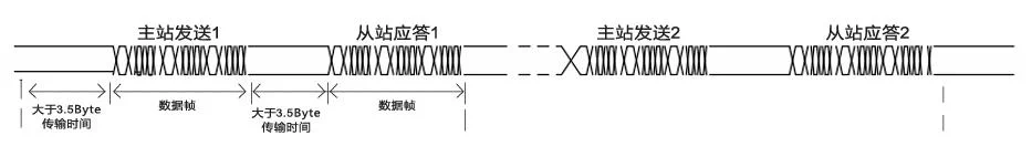 The communication protocol built into the frequency converter is Modbus-RTU slave communication protocol, which can respond to the host’s “query/command”, or make corresponding actions according to the host’s “query/command”, and reply communication data.
The host can refer to a personal computer (PC), industrial control equipment or programmable logic controller (PLC), etc. The host can communicate with a slave individually, or broadcast information to all lower slaves. For the host’s individual access to “query/command”, the accessed slave returns a response frame frequency; for the broadcast information sent by the host, the slave does not need to feed back a response to the host.
The communication protocol built into the frequency converter is Modbus-RTU slave communication protocol, which can respond to the host’s “query/command”, or make corresponding actions according to the host’s “query/command”, and reply communication data.
The host can refer to a personal computer (PC), industrial control equipment or programmable logic controller (PLC), etc. The host can communicate with a slave individually, or broadcast information to all lower slaves. For the host’s individual access to “query/command”, the accessed slave returns a response frame frequency; for the broadcast information sent by the host, the slave does not need to feed back a response to the host.
9.1.3 Communication Data Structure
The Modbus protocol communication data format is as follows, the frequency converter only supports read or write of Word type parameters. The corresponding communication read operation command is 0x03; write operation command is 0x06, does not support read or write operation of bytes or bits:
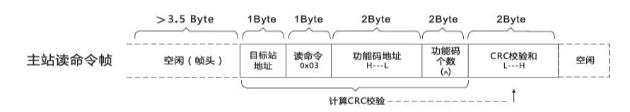 Theoretically, the upper computer can read several continuous function codes at a time (that is, the maximum n can reach 12), but it should be noted that it cannot cross the last function code of this function code group, otherwise it will reply with an error.
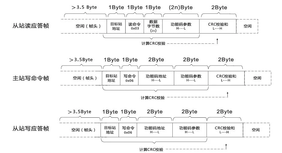 If the slave detects a communication frame error or other reasons lead to unsuccessful reading and writing, it will reply an error frame.
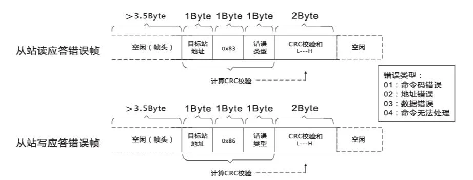
9.1.4 Data Frame Field Description
| Item | Description |
|---|---|
| Frame header START | Idle time greater than 3.5 character transmission time |
| Slave address ADR | Communication address range:1~247;0=broadcast address |
| Command code CMD | 03:Read slave parameters;06:Write slave parameters |
| Function code address H | Internal parameter address of frequency converter, expressed in hexadecimal; divided into function code type and non-function code type (such as running state parameters, running commands, etc.) parameters, see address definition. When transmitting, the high byte is first, then the low byte |
| Function code address L | Same as above |
| Function code number H | Number of function codes read in this frame, if 1 means reading 1 function code. When transmitting, the high byte is first, then the low byte. This protocol can only rewrite 1 function code at a time, and this field is not available. |
| Function code number L | Same as above |
| Data H | Response data, or written data, when transmitting, the high byte is first, then the low byte. |
| Data L | Same as above |
| CRCCHK high byte | Detection value:CRC16 check value. When transmitting, the high byte is first, then the low byte. The calculation method is detailed in the description of CRC check in this section. |
| CRCCHK low byte | Same as above |
| END | 3.5 character time |
9.1.5 CMD Check Mode
Check mode CRC check mode: CRC (Cyclical Redundancy Check) uses RTU frame format, the message includes an error detection field based on CRC method. The CRC field detects the content of the entire message. The CRC field is two bytes, containing a 16-bit binary value. It is calculated by the transmission device and added to the message. The receiving device recalculates the CRC of the received message and compares it with the received CRC field. If the two CRC values are not equal, it indicates that there is an error in transmission. CRC is first stored as 0xFFFF, and then a process is called to process the consecutive 8-bit bytes in the message with the current register value. Only the 8-bit data in each character is valid for CRC, and the start bit, stop bit, and parity bit are invalid. During CRC generation, each 8-bit character is XORed with the register content separately, the result is shifted to the lowest significant bit direction, and the highest significant bit is filled with 0. The LSB is extracted for detection. If the LSB is 1, the register is XORed with a preset value. If the LSB is 0, no operation is performed. This process is repeated 8 times. After the last bit (8th bit) is completed, the next 8-bit byte is XORed with the register’s current value separately. Finally, the value in the register is the CRC value of all bytes in the message. When adding CRC to the message, the low byte is added first, then the high byte. The CRC simple function is as follows:
unsigned int CRC16_CHK(unsigned char *data, unsigned char length)
{
  int j = 0;
  unsigned int crc Oxffff reg:
    while(length--)
    {
       crc reg *data++:
       for(j=0:j<8:j++)
          {
           if(reg crc 0x01)
             {
            reg_crc (reg_crc > 1) 0xa001:
             }
       else
             {
             reg_crc = reg_crc >> 1;
             }
          }
    }
    return reg_crc;
}
9.1.6 Function Code Parameter Address Marking Rules:
Read and write function code parameters (some function codes cannot be changed, only for factory use or monitoring):
The parameter address is expressed by function code group number and label:
High byte: PO-PF (P group) AO-AF (A group) 70-7F (U group)
Low byte: 00-FF
For example: If you want to range function code P3-12 , the access address of the function code is expressed as F30CH
Note: PF group: Neither parameter can be read nor changed; U group: Only readable, not changeable. Some parameters cannot be changed when the frequency converter is running; some parameters cannot be changed regardless of the state of the frequency converter; when changing function code parameters, pay attention to the parameter range, unit and related instructions.
| Function code group number | Communication access address | Communication modification RAM function code address |
|---|---|---|
| P0~PE 组 | 0xF000~0xFEFF | 0x0000~0x0EFF |
| A0~AC 组 | 0xA000~0xACFF | 0x4000 ~0x4CFF |
| U0组 | 0x7000 ~0x70FF | Read only, cannot write |
Note: 1、Due to frequent storage of EEPROM, it will reduce the service life of EEPROM, so some function codes do not need to be stored in communication mode, just change the value in RAM. 2、If it is a P group parameter, to implement this function, just change the high bit F of the function code address to 0 to implement. If it is an A group parameter, to implement this function, just change the high bit A of the function code address to 4 to implement.
Writing RAM corresponding function code address as follows:
High byte: 00-0F(P group) 40-4F(A group)
Low byte:00-FF
For example:Function code P3-12 is not stored in EEPROM, the address is expressed as 030cH ;
Function code A0-05 is not stored in EEPROM, the address is expressed as 4005H ;
Note: This address representation can only be used for writing RAM, not for reading. For all parameters, command code 07H can also be used to implement this function.
9.1.7 Stop/Run Parameter Part:
| Parameter address | Parameter description | Parameter address | Parameter description |
|---|---|---|---|
| 1000H | Communication setting value(decimal)-10000-10000 | 1010H | PID setting |
| 1001H | Running frequency | 1011H | PID feedback |
| 1002H | Bus voltage | 1012H | PLC step |
| 1003H | Output voltage | 1013H | Input pulse frequency, unit 0.01kHz |
| 1004H | Output current | 1014H | Feedback speed,unit 0.1Hz |
| 1005H | Output power | 1015H | Remaining running time |
| 1006H | Output torque | 1016H | All voltage before correction |
| 1007H | Running speed | 1017H | AI2 voltage before correction |
| 1008H | DI input flag | 1018H | AI3 voltage before correction |
| 1009H | DO output flag | 1019H | Line speed |
| 100AH | All voltage | 101AH | Current power-on time |
| 100BH | AI2 voltage | 101BH | Current running time |
| 100CH | AI3 voltage | 101CH | Input pulse frequency,unit 1Hz |
| 100DH | Count value input | 101DH | Communication setting value |
| 100EH | Length value input | 101EH | Actual feedback speed |
| 100FH | Load speed | 101FH | Main frequency X display |
| 1020H | Auxiliary frequency Y display |
Note: 1、Communication setting value is a relative percentage, 10000 corresponds to 100.00%, -10000 corresponds to -100.00%. 2、For data with frequency dimension, this percentage is the percentage of maximum frequency(P0-10); for data with torque dimension, this percentage is P2-10, A2-48, A3-48, A4-48 (torque upper limit digital setting, corresponding to the first, second, third, fourth motors respectively)
Control command input to frequency converter:(write only)
| Command word address | Command function |
|---|---|
| 2000H | 0001:Forward running0002:Reverse running0003:Forward jog0004:Reverse jog0005:Free parking0006:Deceleration parking0007:Fault reset |
Reading frequency converter status:(read only)
| Status word address | Status word function |
|---|---|
| 3000H | 0001:Forward running0002:Reverse running0003:Stopped |
Parameter lock password check:(if return is 888H, it means password check passed)
| Password address | Input password content |
|---|---|
| 1F00H | ***** |
9.1.8 Output Control Commands
| Command word address | Command content | Output control command description |
|---|---|---|
| 2001H | Bit0: DO1 output controlBit1: DO2 output controlBit2: RELAY1 output controlBit3: RELAY2 output controlBit4: FMR output controlBit5: VDO1Bit6: VDO2 | Digital output terminal control:(write only) |
| 2002H | 0~7FFF indicates 0%~100% | Analog output AO1 control:(write only) |
| 2003H | 0~7FFF indicates 0%~100% | Analog output AO2 control:(write only) |
| 2004H | 0~7FFF indicates 0%~100% | Pulse(PULSE)output control:(write only) |
9.1.9 Frequency Converter Fault Description
| Frequency converter fault address | Frequency converter fault information |
|---|---|
| 8000H | 0000:No fault0001:Reserved0002:Acceleration over current0003:Deceleration over current0004:Constant speed over current0005:Acceleration over voltage0006:Deceleration over voltage0007:Constant speed over voltage0008:Buffer resistor overload fault0009:Undervoltage fault000A:Frequency converter overload000B:Motor overload000C:Input phase loss000D:Output phase loss000E:Module overheating000F:External fault0010:Communication abnormal0011:Contactor abnormal0012:Current detection fault0013:Motor tuning fault0014:Encoder/PG card fault0015:Parameter read/write abnormal0016:Frequency converter hardware fault0017:Motor ground short circuit fault0018:Reserved0019:Reserved001A:Running time arrival001B:User-defined fault 1001C:User-defined fault 2001D:Power-on time arrival001E:Load shedding001F:PID feedback loss during operation0028:Fast current limiting timeout fault0029:Motor switching fault during operation002A:Speed deviation too large002B:Motor overspeed002D:Motor over-temperature005A:Encoder line number setting error005B:Encoder not connected005C:Initial position error005E:Speed |
9.1.10 PD Group Communication Parameter Description
| Function code | Name | Setting range | Factory value |
|---|---|---|---|
| Pd-00 | Baud rate | Units digit:MODUBS baud rate0:300BPS1:600BPS2:1200BPS3:2400BPS4:4800BPS5:9600BPS6:19200BPS7:38400BPS8:57600BPS9:115200BPS | 600 |
| Pd-01 | Data format | 0:No parity:data format<8,N,2>1:Even check:data format<8,E,1>2:Odd check:data format<8,0,1> | 0 |
| Pd-02 | Local address | 1~247,0 for broadcast address | 1 |
| Pd-03 | Response delay | 0~20ms | 2ms |
| Pd-04 | Communication timeout time | 0.0s(invalid)0.1~60.0s | 2ms |
| Pd-05 | 0:Non-standard Modbus protocol;1:Standard Modbus protocol | 0 | |
| Pd-06 | Communication read current resolution | 0:0.01A;1:0.1A | 0 |
9.2 Communication Data Address Definition
Communication data can be divided into function code data and non-function code data, the latter including running commands, running status, running parameters, alarm information, etc.
9.2.1 Function Code Data
Function code data is important setting parameters of frequency converters, including P group and A group function parameters, parameter groups are as follows:
| Function code data | Data range | Attribute value |
|---|---|---|
| P group | P0、P1、P2、P3、P4、P5、P6、P7、P8、P9、PA、PB、PC、PD、PE、PF | Readable and writable |
| A group | A0、A1、A2、A3、A4、A5、A6、A7、A8、A9、 AA、AB、AC、AD、AE、AF | Readable and writable |
Function code data communication address definition is as follows:
1、When reading function code data, for P0-PF、A0-AF group function code data, its communication address high sixteen bits are directly the function group number, low sixteen bits are directly the sequence number of the function code in the function group, for example:
P0-16 function parameter:Its communication address is F010H, where F0H represents P0 group function parameter, 10H represents the hexadecimal data format of sequence number 16 in the function group.
AC-08 function parameter:Its communication address is AC08, where ACH represents AC group function parameter, 08H represents the hexadecimal data format of function code sequence number 08 in the function group.
2、When writing function code data, for PO-PF group function code data, its communication address high sixteen bits are divided into 00-0F or F0-FF according to whether it is written into EEPROM, low sixteen bits are directly the sequence number of the function code in the function group, for example:
Write function parameter P0-16:
When EEPROM is needed, its communication address is F010H,
When EEPROM is not needed, its communication address is 0010H.
3、When writing EEPROM data, for A0-AF group function code data, its communication address high sixteen bits are divided into 10-4F or A0-AF according to whether it is written into EEPROM, low sixteen bits are directly the sequence number of the function code in the function group, for example:
Write function parameter AC-08:
When EEPROM is needed, its communication address is AC08H,
When EEPROM is not needed, its communication address is 4C08H.
9.2.2 Non-function Code Data
| Non-function code data | Data range | Attribute value |
|---|---|---|
| Status data | U group monitoring parameters、frequency converter fault description、frequency converter running status | Readable |
| Control parameters | Control command、communication setting value、digital output terminal control、analog output AO1 control、analog output 、AO2 control、high-speed pulse(FMP)output control、parameter initialization | Writable |
9.2.3 Status Data
Status data is divided into U group monitoring parameters, frequency converter fault description, frequency converter running status.
1、U group parameter monitoring parameters
U group monitoring data description see the relevant U0 group function description in the manual, its address definition is as follows:
U0-UF, its communication address high sixteen bits are 70-7F, low sixteen bits are the sequence number of monitoring parameters in the group, for example: U0-11, its communication address is 700BH.
2、Frequency converter fault description
The communication address for reading frequency converter fault is fixed at 8000H, the upper computer can obtain the current frequency converter fault code by reading this address data, and the fault code description is defined in P9-14 function code.
3、Frequency converter running status
The communication address for reading frequency converter running status is fixed at 3000H, the upper computer can obtain the current frequency converter running status information by reading this address data, which is defined as follows:
| Frequency converter running status communication address | Read status word definition |
|---|---|
| 3000H | 1:Forward running2:Reverse running3:Stopped |
9.2.4 Control Parameters
Control parameters are divided into control commands, digital output terminal control, analog output AO1 control, analog output AO2 control, high-speed pulse(FMP)output control.
9.2.5 Control Commands
When P0-02(command source)is selected as 2:communication control, the upper computer can realize start-stop and other related command control of the frequency converter through this communication address, the control command definition is as follows:
| Control command communication address | Command function |
|---|---|
| 2000H | 1:Forward running2:Reverse running3:Forward jog4:Reverse jog5:Free parking6:Deceleration parking7:Fault reset |
9.2.6 Communication Setting Value
Communication setting value is mainly used when frequency source、torque upper limit source、VF separation voltage source、PID given source、PID feedback source are selected as communication given. Its communication address is 1000H, when the upper computer sets this communication address value, its data range is -10000~10000, corresponding to relative given value -100.00%-100.00%.
9.2.7 Digital Output Terminal Control
When the digital output terminal function is selected as 20:communication control, the upper computer can realize the control of the frequency converter digital output terminal through this communication address, which is defined as follows:
| Digital output terminal control communication address | Command content |
|---|---|
| 2001H | BiT0:DO1 output controlBiT1:DO2 output controlBiT2:RELAY1 output controlBiT3:RELAY2 output controlBiT4:FMR output controlBiT5:VDO1BiT6:VDO2 |
9.2.8 Analog Output AO1、AO2.High-speed Pulse Output FMP Control
When the analog output AO1、AO2, high-speed pulse output FMP output function is selected as 12:communication setting, the upper computer can realize the control of the frequency converter analog quantity、high-speed pulse output through this communication address, which is defined as follows:
| Output terminal | Output control communication address | Command content |
|---|---|---|
| AO1 | 2002H | 0~7FFF indicates 0%~100% |
| AO2 | 2003H | 0~7FFF indicates 0%~100% |
| FMP | 2004H | 0~7FFF indicates 0%~100% |
9.2.9 Parameter Initialization
When it is necessary to realize parameter initialization operation on the frequency converter through the upper computer, this function needs to be used.
If PP-00(user password)is not 0, password verification needs to be performed first, after verification, within 30 seconds, the upper computer performs parameter initialization operation.
The communication address for password verification is 1F00H, directly write the correct user password to this address to complete password verification.
The address for communication parameter initialization is 1F01H, its data content is defined as follows:
| Parameter initialization communication address | Command function |
|---|---|
| 1F01H | 1:Restore factory parameters2:Clear record information4:Restore user backup parameters501:Backup current user parameters |
10. Warranty Instructions
Thank you for using our products. To ensure that the products you purchased from our company enjoy quality service, please read the following terms:
Standard Warranty Period
Our company’s general frequency converters provide a standard warranty period of twelve months from the date of factory shipment(subject to the shipping information on the barcode on the fuselage).
Warranty Scope
During the warranty period, if the product fails under normal use conditions, we will provide free product repair for you with the warranty card.
Non-warranty Scope
- Machine damage caused by improper product maintenance, on-site accidents, natural disasters, etc.;
- Machine damage caused by unauthorized disassembly and reassembly or modification of the product;
- The serial number has been changed, removed or incorrect;
- Machine damage caused by the buyer not using the product in accordance with the instruction manual or human factors.
Service after Warranty Period
If the product has exceeded the warranty period, our company will charge on-site service fees, parts fees, labor fees and logistics fees to the final user. For detailed standards, please see the following table:
| Service content | Repair by sending back to factory | On-site repair |
|---|---|---|
| No parts replacement required | Labor cost + round-trip logistics cost | Round-trip travel expenses + labor cost |
| Parts replacement required | Labor cost + round-trip logistics cost + parts cost | Round-trip travel expenses + labor cost + parts cost |
Travel expenses:Round-trip travel expenses of technical personnel for on-site service(including transportation fees, accommodation fees, work meal fees, etc.)
Parts fees:Cost of replaced parts(including any freight/management fees)
Labor fees:Labor fees for technical personnel, including maintenance, repair, installation and debugging
Logistics fees:Logistics fees for faulty products from customers to our company and repaired/replaced products from our company to customers, including other derived fees.
11. Get Installation Support
Need further support?
Quick Support Channels
Installation Support Hotline
+86 150-6499-9739
Monday-Friday: 9:00 - 18:00