Complete VFD Selection Guide: From Load Analysis to Model Determination

Engineer Luo
Low-Voltage Equipment Technical Advisor10 years of experience as a low-voltage equipment technical advisor, specializing in the selection and application of motor control devices such as soft starters and VFDs, having served over 200 industrial projects.
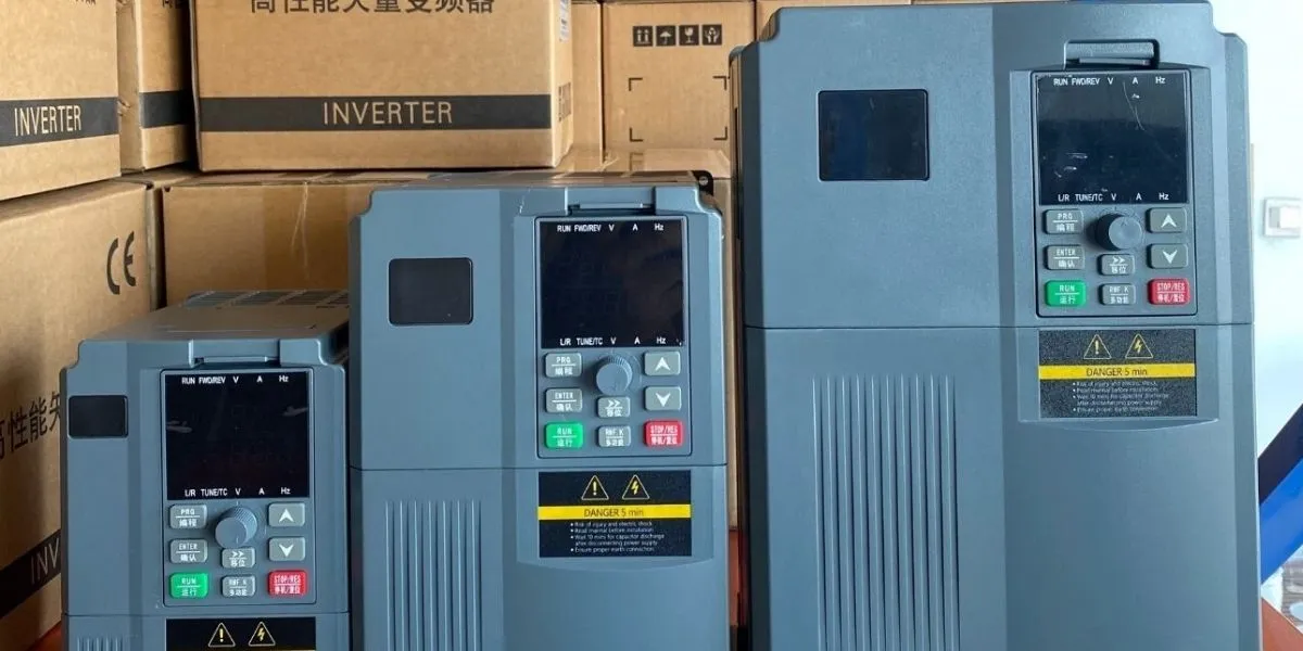
Variable Frequency Drives (VFDs) are among the most widely used motor control devices in industrial automation, but the problems caused by incorrect selection are equally common — from unstable operation and diminished energy savings to frequent tripping, equipment damage, and production line shutdowns. Unlike soft starters, VFDs not only control the starting process but also regulate motor speed throughout operation, making selection more multidimensional and technically demanding. This article walks you through every critical step of VFD selection based on real-world engineering experience. If you need quick selection results, you can use our VFD Intelligent Selection System to get precise model recommendations by simply entering motor parameters.
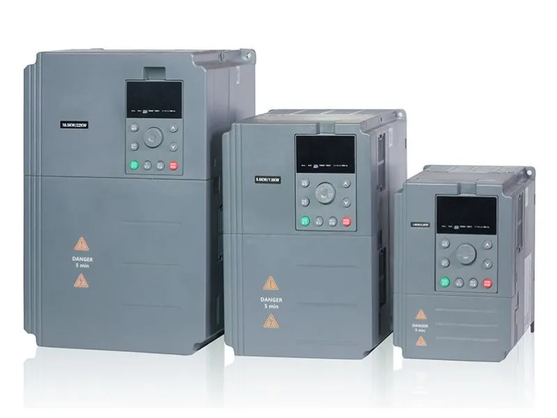
I. Selection Step One: Understand Your Load Characteristics
Load characteristics are the fundamental starting point for VFD selection. Different loads impose completely different requirements on the VFD. Before selecting, you must answer one question: Is your load constant torque or variable torque?
1.1 Constant Torque Loads
Constant torque loads are characterized by the fact that regardless of speed changes, the torque required by the load remains essentially constant. Typical equipment includes:
- Conveyors, belt conveyors
- Extruders, injection molding machines
- Hoists, cranes
- Mixers, internal mixers
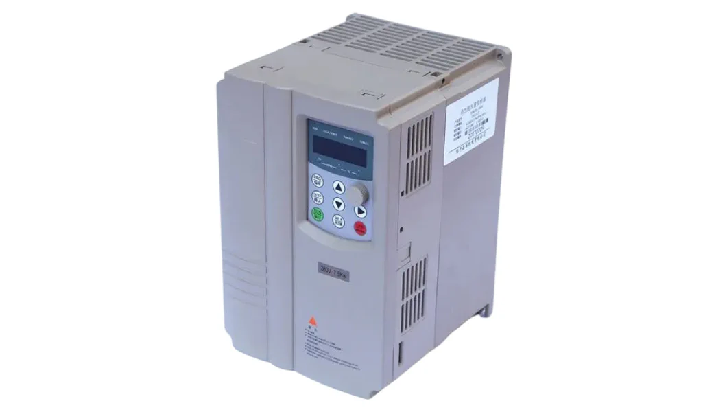
Selection Key Points: Constant torque loads require sufficient torque output across the entire speed range. The VFD must be selected based on the motor’s rated current, with particular attention to low-frequency torque output capability. We recommend choosing a VFD that supports vector control, such as the SK600 Series General-Purpose Vector VFD, which can output 150% starting torque at 0.5Hz (SVC mode), fully meeting the drive requirements of constant torque loads.
1.2 Variable Torque Loads (Fans and Pumps)
Variable torque loads are characterized by torque being proportional to the square of speed and power being proportional to the cube of speed. Typical equipment includes:
- Centrifugal fans, induced draft fans
- Centrifugal pumps, deep-well pumps
- HVAC units, cooling towers
Selection Key Points: Variable torque loads require very little torque at low-frequency operation, so low-frequency torque requirements for the VFD are not demanding — V/F control is usually sufficient. More importantly, the energy savings are significant — according to the affinity laws, a 20% reduction in speed can reduce power consumption by approximately 50%. This is the core reason VFDs are widely applied in fan and pump applications. For detailed information on VFD applications in constant pressure water supply, refer to How VFDs Achieve Constant Pressure Water Supply: Principles and Practice.
1.3 Quick Comparison of Selection Differences
| Comparison Dimension | Constant Torque Load | Variable Torque Load |
|---|---|---|
| Recommended Control Method | Vector Control (SVC/FVC) | V/F Control |
| Power Selection | ≥ Motor power, upsize 1~2 ratings for heavy loads | ≥ Motor power sufficient |
| Low-Frequency Torque Requirement | High (150%+ starting torque needed) | Low (light load at low frequency) |
| Speed Range | Typically 1:10~1:50 | Typically 1:2~1:4 |
| Energy Savings Potential | Limited (mainly through process optimization) | Significant (20%~50%) |
| Typical Applications | Conveyors, extruders, hoists | Fans, pumps, HVAC |
II. Power Matching — The Hard Metric for Selection
Power matching is the most fundamental and critical aspect of VFD selection. Many engineers habitually match motor power “one-to-one,” but actual selection is far more complex.
2.1 Core Principle: Current First, Not Power
The core principle of VFD selection is VFD Rated Current ≥ Motor Rated Current × Load Factor, rather than simply comparing power ratings. The reasons are:
- Motors of the same power may have significantly different rated currents due to varying efficiency and power factor
- VFD overload capacity is specified based on current
- Current is the direct factor determining VFD heating and safety
Load Factor Recommendations:
- Standard loads (fans, pumps): 1.0~1.1×
- Heavy-duty loads (conveyors, extruders): 1.15~1.2×
- Ultra-heavy loads (crushers, ball mills): 1.3× or above
- Frequent start/stop (injection molding machines, elevators): 1.2~1.5×
You can use the VFD Intelligent Selection System to enter motor parameters — the system will automatically calculate the required current and recommend matching models.
2.2 G-Type vs. P-Type VFDs
The SK600 series VFDs come in G-Type and P-Type specifications, which are easily confused during selection:
| Comparison Item | G-Type (Constant Torque) | P-Type (Variable Torque) |
|---|---|---|
| Applicable Load | Constant torque loads | Variable torque loads (fans & pumps) |
| Overload Capacity | 150% rated current for 60s | 120% rated current for 60s |
| Rated Current at Same Power | Higher | Lower |
| Price at Same Power | Slightly higher | Slightly lower |
Selection Advice: Constant torque loads must use G-Type VFDs; variable torque loads can choose P-Type to reduce cost, but if short-term overload conditions exist, G-Type is still recommended.
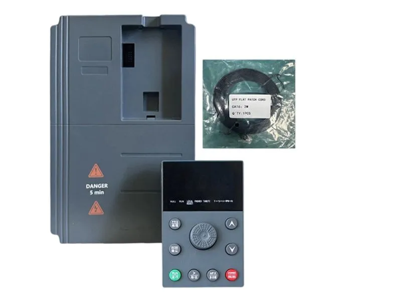
2.3 Multi-Motor Parallel Drive Selection
When one VFD drives multiple motors in parallel (e.g., multiple identical pumps), the selection must satisfy:
VFD Rated Current ≥ Sum of All Driven Motors’ Rated Currents × 1.1
Also note:
- Motor power and parameters should be as consistent as possible
- The VFD can only use V/F control mode (vector control for individual motors is not possible)
- Each motor needs a separate thermal relay for overload protection
- Cable length between VFD and motors should not be excessive
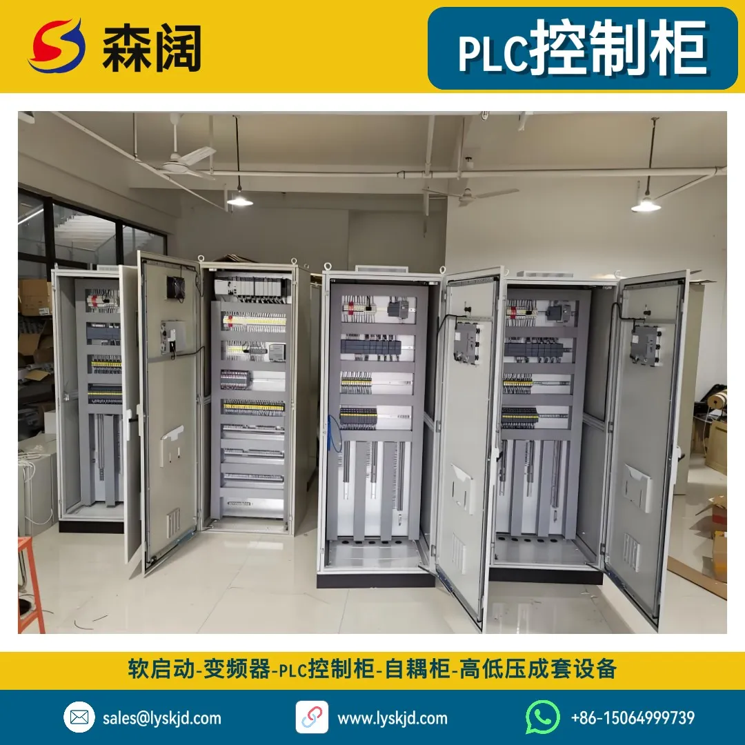
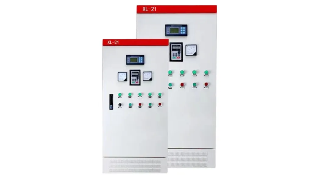
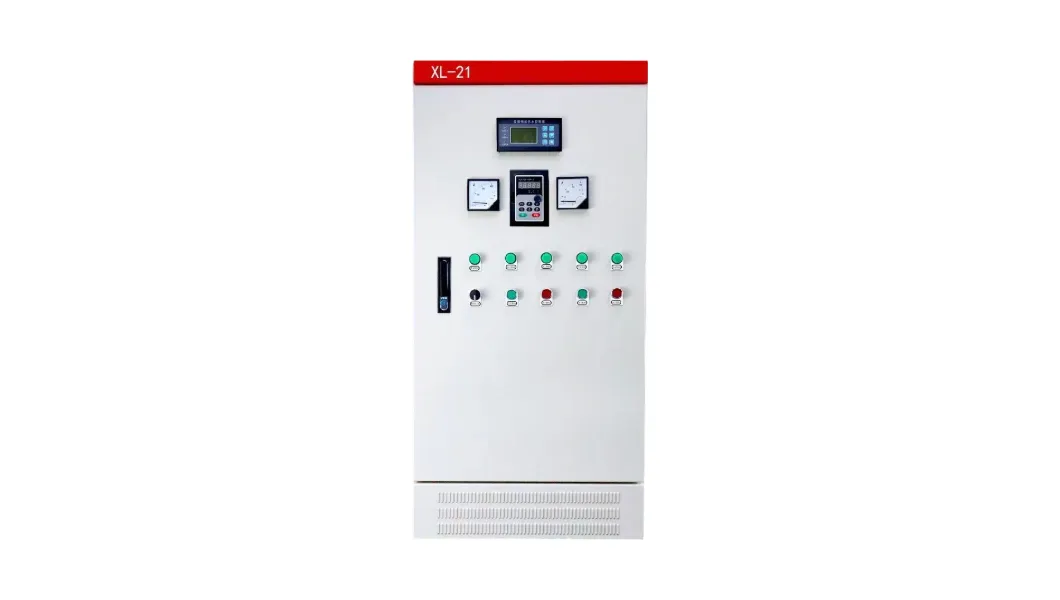
For multi-pump constant pressure water supply systems, we recommend the SKBG Series VFD Control Cabinet, which features built-in multi-pump control logic for automatic switching and cyclic operation.
III. Control Method — The Key Choice Determining Performance and Cost
The VFD’s control method directly determines speed regulation accuracy, dynamic response, and cost — it is a technical parameter that must be clearly defined during selection.
3.1 V/F Control
V/F control (constant voltage-to-frequency ratio control) is the most basic VFD control method, controlling the motor by maintaining a fixed ratio between output voltage and frequency.
Characteristics:
- Simple structure, low cost
- Speed regulation accuracy approximately 1%~2%
- Weak low-frequency torque, requires torque boost compensation
- Suitable for applications with low precision requirements
Applicable Scenarios: Standard fans, pumps, simple conveyor drives
3.2 Open-Loop Vector Control (SVC)
Open-loop vector control (sensorless vector control) estimates rotor flux position through a motor mathematical model, achieving decoupled control of torque and flux.
Characteristics:
- Speed regulation accuracy approximately 0.5%, speed ratio 1:100
- Strong low-frequency torque, 150% rated torque output at 0.5Hz
- No encoder required, simple installation and maintenance
- Supports torque control function
Applicable Scenarios: Conveyors, mixers, extruders, and other applications requiring low-speed performance
3.3 Closed-Loop Vector Control (FVC)
Closed-loop vector control (vector control with speed sensor) installs an encoder on the motor shaft to directly obtain speed feedback, achieving the highest precision speed and torque control.
Characteristics:
- Speed regulation accuracy <0.5%, speed ratio 1:1000
- 180% rated torque output at 0Hz
- Supports high-precision torque control and position control
- Requires encoder installation, increasing system complexity
Applicable Scenarios: CNC machines, precision machining, high-speed paper making, wire drawing machines, and other high-precision applications
3.4 Comparison of Three Control Methods
| Comparison Dimension | V/F Control | Open-Loop Vector (SVC) | Closed-Loop Vector (FVC) |
|---|---|---|---|
| Speed Regulation Accuracy | 1%~2% | Approx. 0.5% | <0.5% |
| Speed Range | 1:10 | 1:100 | 1:1000 |
| Starting Torque | 100%/3Hz | 150%/0.5Hz | 180%/0Hz |
| Torque Control | Not supported | Supported (±5% accuracy) | Supported (±5% accuracy) |
| Encoder | Not required | Not required | Required |
| Cost | Lowest | Medium | Highest |
| Typical Applications | Fans, pumps | Conveyors, mixers | CNC machines, wire drawing |
💡 Selection Advice: Don’t blindly pursue high-precision control. When V/F control meets the requirements, choosing vector control only increases cost and commissioning difficulty. Selecting the control method based on actual process requirements is the most economical approach.
IV. Voltage Level — A Matching Condition That Cannot Be Overlooked
The VFD’s voltage level must match the power supply and motor voltage — this is a basic prerequisite for selection and a common source of errors.
4.1 Common Voltage Levels
| Voltage Level | Power Source Type | Suitable Motor | Typical Applications |
|---|---|---|---|
| Single-phase 220V | Residential/commercial single-phase | Single-phase 220V motor | Small fans, home appliances |
| Three-phase 220V | Three-phase industrial power (imported equipment) | Three-phase 220V motor | Imported equipment |
| Three-phase 380V | Standard industrial power (China) | Three-phase 380V motor | Factories, pump rooms, HVAC |
| Three-phase 480V | North American standard industrial power | Three-phase 480V motor | Export equipment, joint venture factories |
| Three-phase 690V | High-voltage industrial power | Three-phase 690V motor | Mining, metallurgy |
| Three-phase 1140V | Special mining power | Three-phase 1140V motor | Underground coal mines |
The SK600 series VFDs support six voltage levels: single-phase 220V, three-phase 220V, three-phase 380V, three-phase 480V, three-phase 690V, and three-phase 1140V, covering the 0.75kW~450kW power range to meet the vast majority of application needs.
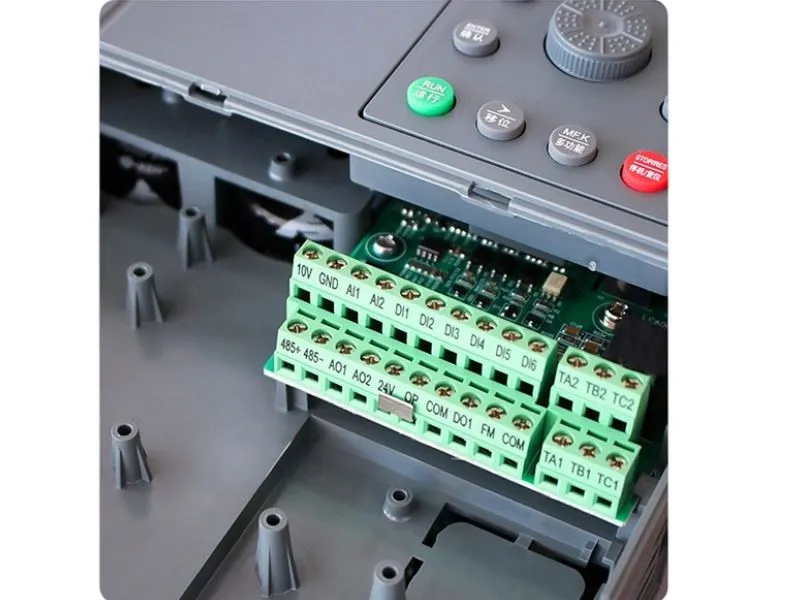
⚠️ Never connect a low-voltage VFD to a higher-voltage power supply — it will directly cause internal component burnout! When connecting a high-voltage VFD to a lower-voltage supply, output power will be proportionally limited. We recommend always choosing a VFD with a voltage level that exactly matches your system.
V. Environmental Conditions — The Hidden Factor Affecting Lifespan and Reliability
5.1 Ambient Temperature
VFD rated current is specified at a reference ambient temperature of 40°C. Derating is required above 40°C:
Actual Available Current = Rated Current × Derating Factor
| Ambient Temperature | Derating Factor |
|---|---|
| ≤40°C | 1.0 |
| 45°C | 0.95 |
| 50°C | 0.88 |
| 55°C | 0.82 |
| 60°C | Not recommended |
⚠️ VFDs generate significantly more internal heat than soft starters, making thermal design particularly critical. For cabinet installation, ensure adequate ventilation space above and below (spacing ≥30cm for models 30kW and above).
5.2 Altitude
Above 1000 meters, reduced air density decreases cooling capacity and air insulation strength:
- 1000~2000m: Current derating 5%
- 2000~3000m: Current derating 10%
- 3000~4000m: Current derating 15%
- Above 4000m: Consult the manufacturer
5.3 Protection Rating and Installation Method
| Installation Method | Protection Rating | Applicable Environment | Notes |
|---|---|---|---|
| Wall-mount | IP20 | Inside distribution cabinet | Most common, requires dedicated cabinet |
| Wall-mount | IP40 | Dry workshops | Higher dust protection |
| Cabinet-type | IP54 | Humid/dusty | Pump rooms, outdoor |
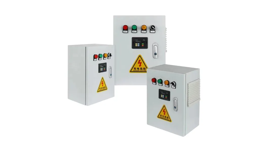
For applications requiring standalone installation, we recommend the SKBG Series VFD Control Cabinet, whose cabinet design provides a higher protection rating with professionally optimized internal cooling.
VI. Communication and Integration — New Requirements for the Smart Era
Modern industry demands increasingly strong communication capabilities from VFDs. Selection must consider integration requirements with host systems.
6.1 Common Communication Protocols
| Protocol | Transmission Rate | Transmission Distance | Typical Applications |
|---|---|---|---|
| Modbus-RTU | 115.2kbps | 1200m | Most universal, supported by nearly all PLCs |
| Profibus-DP | 12Mbps | 100m | Standard for Siemens systems |
| CANopen | 1Mbps | 250m | Common in motion control |
| CANlink | 1Mbps | 250m | Senkuo proprietary protocol, multi-VFD coordination |
| Ethernet | 100Mbps | 100m | Remote monitoring, big data collection |
The SK600 series VFDs support four bus protocols: Modbus-RTU, Profibus-DP, CANlink, and CANopen, which can be flexibly configured through expansion cards to meet different system integration needs.
6.2 User Programmable Function
For applications with special process requirements, the SK600 series also supports user programmable functionality — through the PC60/PC1 user programmable card, users can perform secondary development using ladder logic and other methods to implement custom logic control without additional PLC configuration, significantly reducing system cost.
VII. VFD vs. Soft Starter — When Should You Choose a VFD?
This is the most frequently asked question during selection. The core difference between the two is:
- Soft Starter: Only controls the starting/stopping process; the motor runs at full speed during operation — no speed regulation capability
- VFD: Controls motor speed throughout operation, enabling stepless speed adjustment, but at a higher cost
7.1 When to Choose a VFD
- You need to adjust motor speed based on process requirements (e.g., constant pressure water supply, fan airflow regulation)
- Significant energy savings are needed (fan and pump speed regulation can save 20%~50% energy)
- Precise speed control or torque control is required
- Frequent forward/reverse operation or rapid braking is needed
7.2 When to Choose a Soft Starter
- The motor always runs at rated speed with no need for speed adjustment
- You only need to solve starting current impact issues
- Budget is limited, seeking cost-effectiveness
- The installation environment has strict harmonic requirements (VFDs produce harmonics)
For detailed soft starter selection methods, refer to Complete Soft Starter Selection Guide: From Parameters to Applications. For advantages of soft starters compared to VFDs, refer to Soft Starter Core Advantages Comparison: Redefining Efficiency and Reliability in Motor Control and Soft Starter Core Advantages Comparison: Stability as the Core, Building the Foundation of Industrial Operation.

VIII. Peripheral Electrical Component Selection — The Often-Overlooked Supporting Aspect
VFD selection is not just about choosing the VFD unit itself — peripheral electrical component selection is equally important. Here are the key points for SK600 series VFD peripheral component selection:
8.1 Input-Side Circuit Breaker (MCCB)
Circuit breakers provide short-circuit protection and isolation on the VFD’s power supply side. Selection requirements:
- Rated current ≥ 1.2~1.5× VFD input current
- Breaking capacity should exceed system short-circuit current
- C-type or D-type trip curve circuit breakers are recommended
8.2 Input-Side AC Contactor
Contactors are used for daily switching control of the VFD. Selection requirements:
- Rated current ≥ VFD input current
- Coil voltage should match the control circuit voltage
- Frequent VFD start/stop via contactor is not recommended (use control terminals instead)
8.3 Input-Side AC Reactor
Input reactors suppress harmonic currents generated by the VFD, protecting power quality:
- For VFDs ≥22kW, input reactors are strongly recommended
- Reactor impedance of 3%~5% is recommended
- When multiple VFDs operate in parallel, each must be equipped with one
8.4 Output-Side Components
- Output Contactor: Switching the output contactor while the VFD is running is not recommended — it can cause overcurrent tripping or even damage the inverter module
- Output Reactor: When cable length from VFD to motor exceeds 50m, an output reactor is recommended to suppress dV/dt voltage spikes
- Braking Resistor: Required for applications needing rapid braking or for potential energy loads (e.g., hoists, centrifuges)
💡 For detailed peripheral component selection parameters, refer to the Peripheral Electrical Component Selection Table on the SK600 product page.
IX. Selection Process Summary
Combining all the factors above, VFD selection can follow this standardized process:
- 1 Analyze Load Characteristics: Constant torque or variable torque? Determine load type and operating conditions
- 2 Determine Motor Parameters: Rated power, rated voltage, rated current, power factor, number of poles
- 3 Choose Control Method: V/F, open-loop vector (SVC), or closed-loop vector (FVC)
- 4 Determine Power Rating: Current-first approach, select G-Type or P-Type based on load factor
- 5 Evaluate Environmental Conditions: Temperature, altitude, protection rating, calculate derating factors
- 6 Confirm Communication Requirements: Whether PLC/host communication is needed, select protocol
- 7 Select Peripheral Components: Circuit breakers, contactors, reactors, braking resistors, etc.
- 8 Finalize the Solution: Integrate all factors to determine VFD model and supporting scheme
X. Common Selection Mistakes and How to Avoid Them
Mistake 1: Looking Only at Power, Ignoring Current
Many engineers select VFDs by directly matching motor power “one-to-one,” ignoring current matching. In reality, motors of the same power can have rated currents differing by more than 10% due to varying efficiency and power factor.
Correct Approach: Current first — VFD rated current ≥ Motor rated current × Load factor.
Mistake 2: Blindly Pursuing Vector Control
Some users always choose vector control regardless of the load, thinking “higher precision is better.” In reality, for standard fans and pumps, V/F control is perfectly adequate, and vector control only adds commissioning difficulty and cost.
Correct Approach: Select the control method based on actual process requirements — good enough is best.
Mistake 3: Ignoring Cable Length
VFDs output PWM (pulse-width modulated) waveforms. Long cables can produce dV/dt voltage spikes at the motor terminals, potentially damaging motor insulation. When cable length exceeds 50m, an output reactor must be installed.
Correct Approach: No additional measures needed for cable lengths up to 50m; install output reactor for 50~100m; install sine wave filter for lengths exceeding 100m.
Mistake 4: Neglecting Harmonic Effects
VFDs are typical non-linear loads that generate significant harmonic currents injected into the power grid, affecting other equipment on the same network. The larger the VFD power, the more severe the harmonic impact.
Correct Approach: For VFDs above 22kW, input reactors are recommended; for multiple VFDs in parallel or applications with strict power quality requirements, active power filters (APF) or passive filters should be installed. For harmonic mitigation in smart power distribution systems, refer to Application and Advantages of Smart Power Distribution Systems in Modern Factories and Application and Development of Smart Power Distribution Systems in Industrial Fields.
Mistake 5: Connecting Contactors on the Output Side
Switching output-side contactors while the VFD is running generates massive transient overcurrent — at best causing the VFD to trip, at worst damaging the inverter module.
Correct Approach: If load switching is required, stop the VFD output first before operating the contactor. Alternatively, use the VFD’s multi-motor switching function (if supported).
XI. Quick Selection Reference Table
| Application Scenario | Recommended Control | Model Type | Power Margin | Recommended Product |
|---|---|---|---|---|
| Centrifugal Fan | V/F Control | P-Type | 1.0× | SK600 P-Type |
| Constant Pressure Water Supply | V/F + PID | P-Type | 1.0~1.1× | SKBG Control Cabinet |
| Conveyor Belt | Open-Loop Vector (SVC) | G-Type | 1.1~1.2× | SK600 G-Type |
| Extruder | Open-Loop Vector (SVC) | G-Type | 1.2× | SK600 G-Type |
| Hoist | Closed-Loop Vector (FVC) | G-Type + Braking Resistor | 1.2~1.3× | SK600 G-Type |
| CNC Machine | Closed-Loop Vector (FVC) | G-Type + Encoder | 1.2× | SK600 G-Type |
| Injection Molding Machine | Open-Loop Vector (SVC) | G-Type | 1.3× | SK600 G-Type |
| Wire Drawing Machine | Closed-Loop Vector (FVC) | G-Type + Encoder | 1.2× | SK600 G-Type |
XII. Final Thoughts
VFD selection is a systems engineering effort involving comprehensive consideration across multiple dimensions: load characteristics, control methods, power matching, voltage levels, environmental conditions, communication requirements, and peripheral components. The core principle of selection is: determine the control method based on load characteristics, determine the power rating based on current, apply derating corrections based on environmental conditions, and select communication solutions based on system integration requirements.
If you still have questions during the selection process, here are ways to get professional support:
- Use the VFD Intelligent Selection System for quick selection recommendations
- Use the Motor Starting Current Calculator to calculate motor parameters
- Learn about the detailed technical parameters of the SK600 Series General-Purpose Vector VFD
- Learn about the cabinet solution of the SKBG Series VFD Control Cabinet
If your application only requires starting protection without speed regulation, refer to the Complete Soft Starter Selection Guide for a more economical solution. For overall low-voltage distribution system selection, refer to Industrial Low-Voltage Distribution Cabinet Selection Guide and Application Practice; for high-voltage distribution equipment selection, refer to Technical Features and Selection Guide for High Voltage Switchgear; for traditional reduced-voltage starting solutions, learn about the technical features of the Autotransformer Reduced Voltage Starting Cabinet.
Choosing the right VFD is not just about protecting your equipment — it’s about safeguarding the efficient, energy-saving, and stable operation of your entire production system. We hope this article helps you avoid common pitfalls and get it right the first time.