Complete PLC Control Cabinet Guide: From Working Principles to Industrial Applications

Engineer Luo
Industrial Automation Technical Advisor10 years of experience as an industrial automation technical advisor, specializing in PLC programming, electrical control system design and commissioning, having delivered over 200 industrial automation projects.
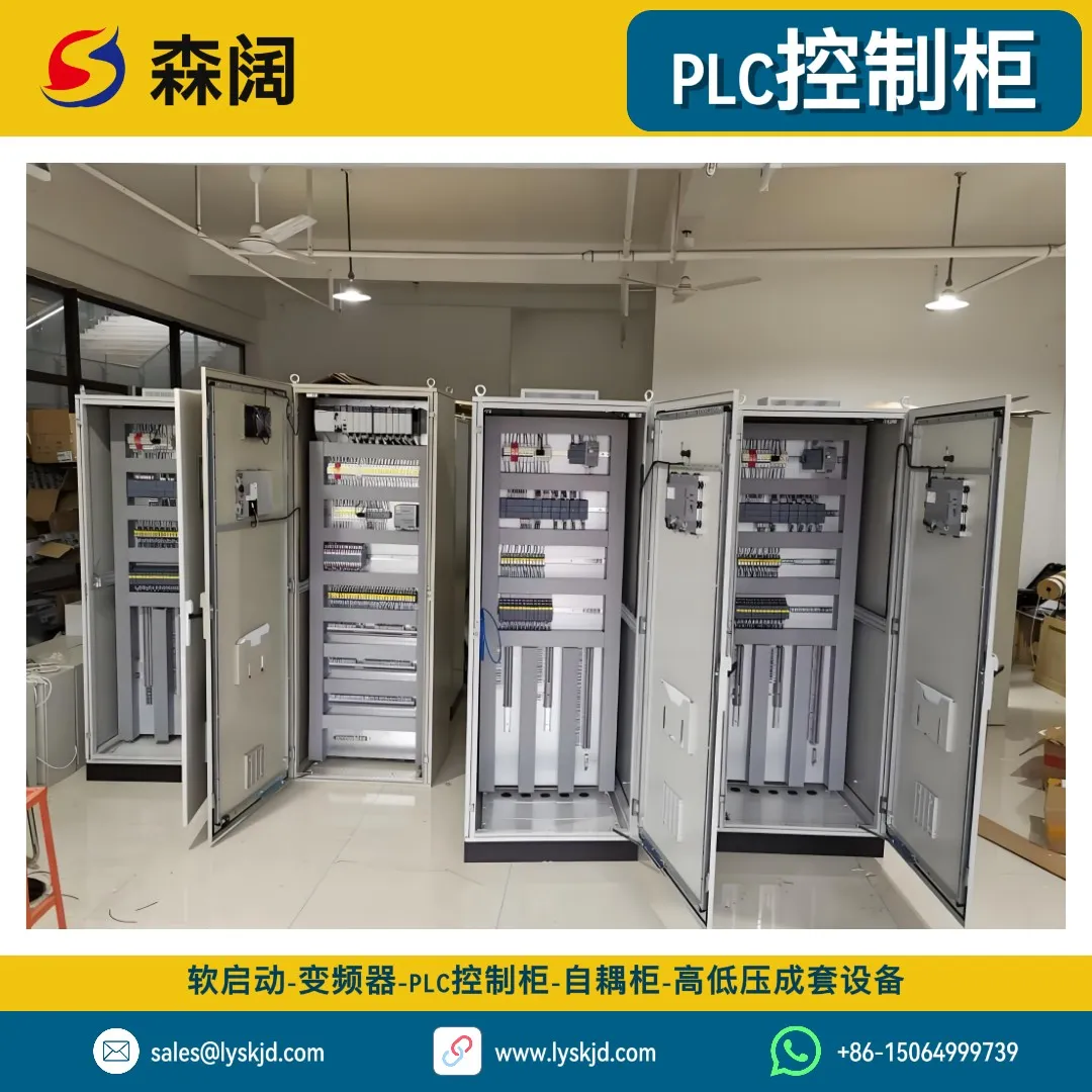
If you walk into any modern factory, you can almost always find a metal cabinet filled with buttons, indicator lights, and cables, quietly running and directing the rhythm of the entire production line — this is the PLC control cabinet. It is the “brain” of the industrial automation system, determining when machines start, stop, and alarm. This article will use plain language to help you understand PLC control cabinets from scratch.
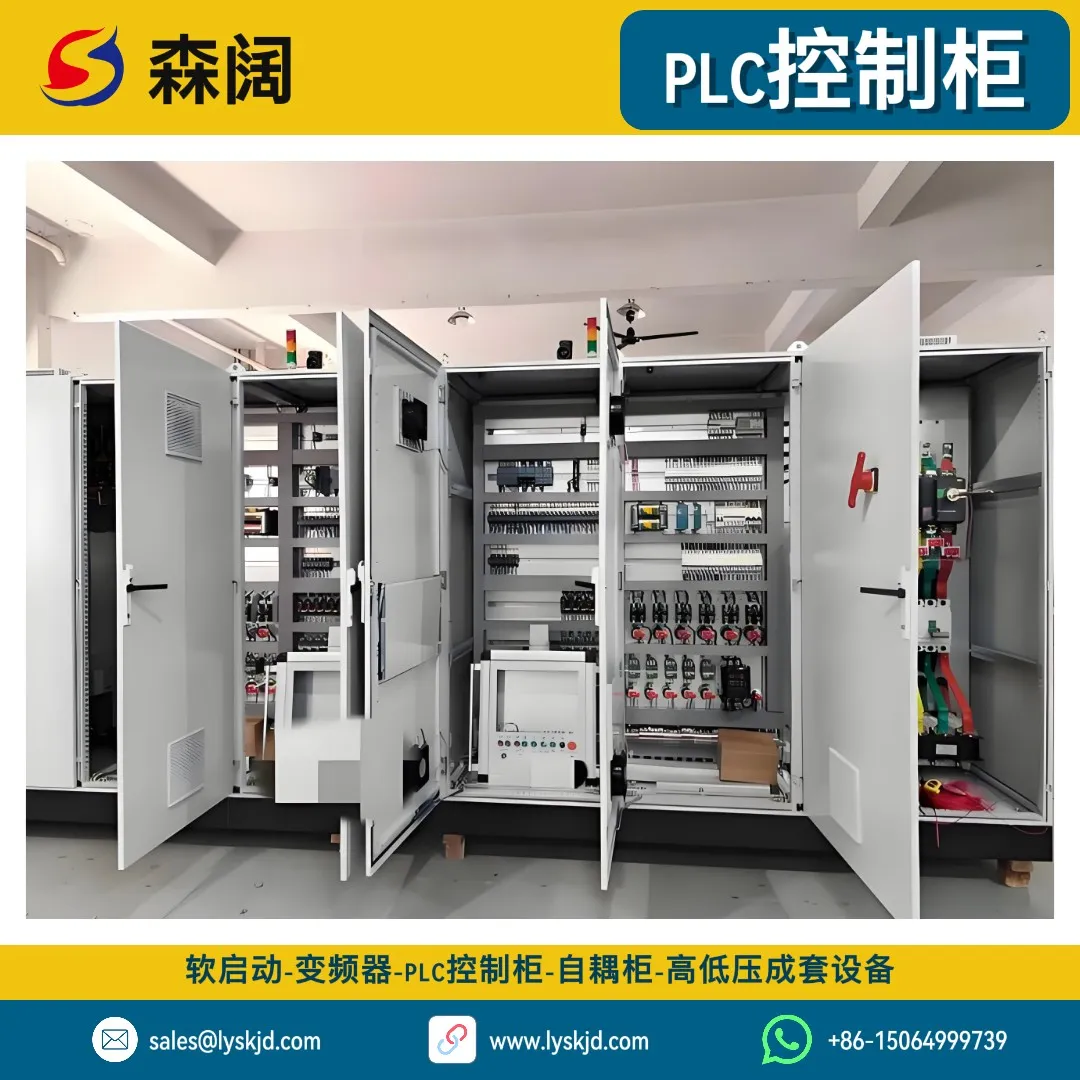
I. What is a PLC? — Installing a “Brain” for Industrial Machines
1.1 Definition of PLC
A PLC (Programmable Logic Controller) is a digital electronic operating system designed specifically for industrial environments. It internally stores instructions for performing logic operations, sequential control, timing, counting, and arithmetic operations, and controls various types of mechanical equipment or production processes through digital or analog inputs and outputs.
Simply put, a PLC is an “industrial-grade mini-computer”, but it’s more rugged than a regular computer — it can operate stably in harsh environments with dust, vibration, high temperatures, and electromagnetic interference.
1.2 The Birth of PLC: Starting from the Automotive Production Line
The story of PLC begins with the American automotive industry in the 1960s. At that time, General Motors (GM) had to rewire relay control cabinets every time they changed production line models — often involving hundreds or thousands of relays, and changing wiring once meant weeks of downtime, wasting time and effort.
In 1968, GM published the famous “Ten Specifications,” hoping to find a controller that was as flexible as a computer and as reliable as a relay. In 1969, Bedford Associates delivered the world’s first PLC — the MODICON 084. From then on, changing a production line only required modifying the program, not rewiring, and industrial control entered the software era.
💡 Interestingly, the “Controller” in PLC’s English name Programmable Logic Controller was deliberately chosen over “Computer” in early patents to emphasize that it is a “controller” rather than a “computer” — reliability was the top priority.
II. How Does a PLC Work? — The Mystery of the Scan Cycle
The key to understanding how a PLC works lies in one word: Scan Cycle.
2.1 The Three-Step Loop
Unlike the human brain which responds “at any time,” a PLC works in a cyclic scanning mode. Each scan cycle includes three phases:
- 1 Input Sampling Phase: The PLC reads the status of all input terminals (whether buttons are pressed, whether sensors are triggered) and stores the results in the "input image register." Changes in external signals are not immediately responded to at this point.
- 2 Program Execution Phase: The PLC executes the user-written program from top to bottom, left to right, performing logic operations based on the input image register and internal states, and writes the results to the "output image register."
- 3 Output Refresh Phase: The PLC sends the contents of the output image register to the output terminals to drive actuators such as contactors and solenoid valves. Then it enters the next scan cycle.
2.2 How Fast is the Scan Cycle?
Modern PLC scan cycles are typically between 1~50 milliseconds, meaning the PLC can complete dozens to hundreds of “read-compute-output” cycles per second. For most industrial processes (such as temperature control, production line tempo), this speed is more than sufficient.
⚠️ But note: if the program is too long or too complex, the scan cycle will lengthen, which may cause delayed response to fast signals. Therefore, PLC programming emphasizes “concise and efficient.”
III. Opening Up a PLC Control Cabinet: What’s Inside?
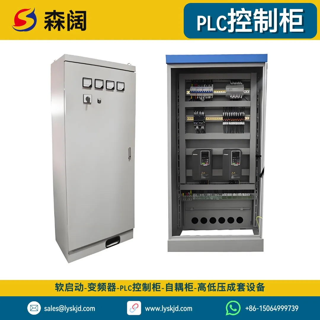
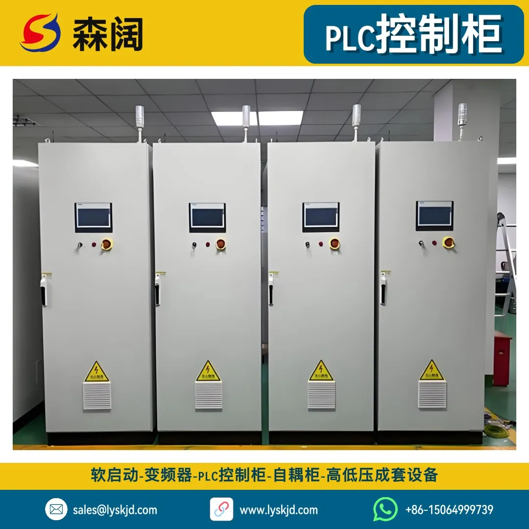
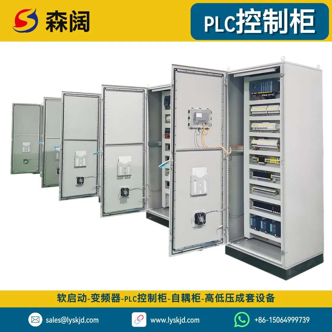
A complete PLC control cabinet consists of the following main parts, from outside to inside:
3.1 PLC Host (CPU Module)
This is the “brain core” of the control cabinet, responsible for storing programs, executing operations, and scheduling communications. CPUs of different levels vary significantly in scan speed, program capacity, and instruction set:
| CPU Level | Scan Cycle | Program Capacity | Typical Application |
|---|---|---|---|
| Small | 0.5~2ms | Several KB~tens of KB | Single equipment, small lines |
| Medium | 0.1~0.5ms | Tens of KB~hundreds of KB | Medium lines, process control |
| Large | <0.1ms | Hundreds of KB~several MB | Large factories, distributed systems |
3.2 I/O Modules — The PLC’s “Eyes” and “Hands”
I/O (Input/Output) modules are the bridge for communication between the PLC and field devices:
- Digital Input (DI): Receives on/off signals from buttons, limit switches, proximity switches
- Digital Output (DO): Drives contactors, relays, solenoid valves, indicator lights
- Analog Input (AI): Collects continuously changing signals such as temperature, pressure, flow, level (4-20mA/0-10V)
- Analog Output (AO): Outputs continuous control signals, such as sending speed commands to a VFD
3.3 Communication Modules — Letting Devices “Talk”
Modern industry emphasizes “networking.” PLCs exchange data with host computers, VFDs, touch screens and other devices through communication modules. Common protocols include:
- Modbus RTU/TCP: The most universal industrial protocol, supported by almost all devices
- Profibus/Profinet: Mainstream protocols in the Siemens ecosystem
- Ethernet: Used for remote monitoring and big data acquisition
For the application of communication networking in smart power distribution systems, see Application and Development of Smart Power Distribution Systems in Industrial Fields.
3.4 HMI Human-Machine Interface — The Window Between Human and Machine
The HMI (Human-Machine Interface) is typically a color touch screen that displays process flowcharts, operating parameters, and alarm information in real time. Operators can start/stop equipment and modify parameters on the screen. It makes complex control systems “visualized.”
3.5 Electrical Control Components
The cabinet is also equipped with circuit breakers, contactors, thermal relays, switching power supplies and other electrical components for switching, protection, and isolation of the main circuit. For the selection methods of these components, see Industrial Low-Voltage Distribution Cabinet Selection Guide and Application Practice.
IV. What Language Does a PLC Use? — Five Languages of IEC 61131-3
Many people think PLC programming is difficult, but the international standard IEC 61131-3 defines five programming languages, each with its own characteristics — there’s always one for you:
4.1 Ladder Diagram (LD) — The Electrician’s Favorite
The ladder diagram looks like a relay control circuit diagram, with two vertical lines on the left and right like the sides of a “ladder,” and contacts and coils in between. It’s intuitive and easy to understand, making it the most commonly used PLC programming language, especially popular among electrical engineers.
    |   Start Btn    Stop Btn          Coil   |
    |----[ ]--------[/]-------------( )---|
    |     |                               |
    |   Seal-in Contact                  |
    |----[ ]------------------------------|
4.2 Function Block Diagram (FBD) — Building Block Programming
FBD combines logic using “function blocks” like building blocks. Each block performs a function (such as timing, counting, PID), and outputs can be connected to other blocks’ inputs. It’s suitable for modular design of complex logic.
4.3 Sequential Function Chart (SFC) — Flowchart Thinking
SFC describes process flows using “steps” and “transitions,” particularly suitable for sequential control scenarios (such as a filling line: bottle in → fill → cap → bottle out).
4.4 Instruction List (IL) — The PLC’s “Assembly Language”
IL is similar to assembly language, written with text instructions. It has high execution efficiency but poor readability and is now rarely used.
4.5 Structured Text (ST) — Like Writing C
ST is a high-level text language that supports IF/THEN, FOR loops, and function calls. It’s suitable for complex algorithms and data processing, and is increasingly favored by young engineers.
💡 In practice, engineers typically mix multiple languages: main logic in ladder diagram, complex calculations in structured text, flow control in sequential function chart — each playing to its strengths.
V. What Can a PLC Do? — Five Application Scenarios
5.1 Production Line Automation
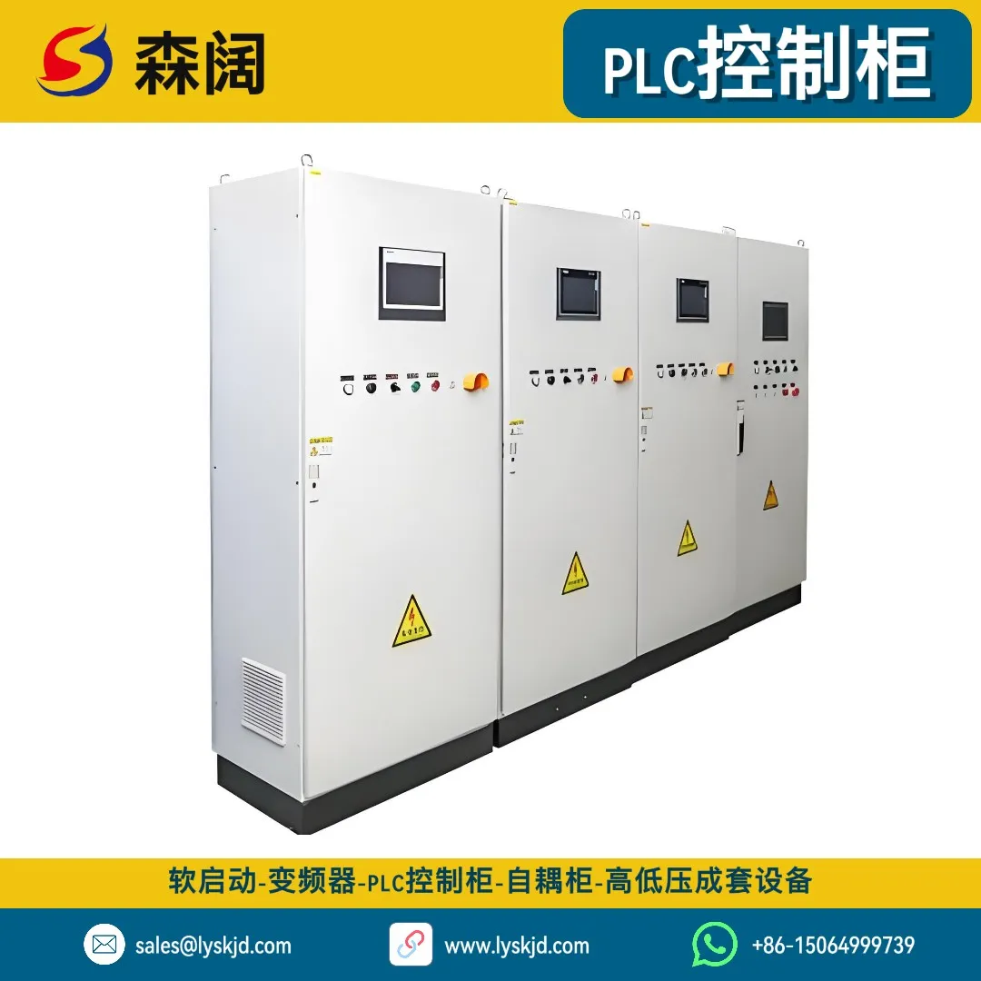
This is the PLC’s most classic battlefield. From food filling to automotive assembly, PLCs control conveyor belt start/stop, robotic arm grasping, and workstation tempo. A modern production line may have dozens of PLCs working together, achieving whole-line linkage through industrial Ethernet.
5.2 Water Treatment and Environmental Protection
The influent pumps, aeration fans, dosing pumps, and dewatering machines of a sewage treatment plant are all automatically regulated by PLCs according to process curves. Combined with a SCADA host system, unattended operation can be achieved. PLCs can also adjust dosing amounts in real time based on influent/effluent water quality, ensuring compliance while saving chemicals.
5.3 HVAC
In large shopping mall central air conditioning systems, PLCs control the number of operating units and speeds of chillers, cooling towers, and water pumps based on return water temperature, achieving constant temperature and humidity while significantly saving energy. Here, PLCs often work with VFDs. For the principles of variable frequency speed regulation, see Complete VFD Selection Guide.
5.4 Power Monitoring
In power distribution rooms, PLCs collect voltage, current, and power factor of each circuit, achieving load monitoring, reactive power compensation, and fault alarms. Together with Low-Voltage Distribution Cabinets and XL-21 Power Distribution Cabinets, they form a complete smart power distribution system.
5.5 Buildings and Municipal
Elevator control, traffic signals, bridge lighting, landscape fountains… these facilities we encounter daily all have PLCs behind them. It’s reliable, durable, and programmable — the ideal choice for municipal engineering.
VI. PLC vs Relay vs Microcontroller vs Industrial PC
Beginners often ask: since they’re all control devices, why does industry specifically choose PLCs? Let’s make it clear with one table:
| Dimension | Relay Control | Microcontroller | PLC | Industrial PC |
|---|---|---|---|---|
| Reliability | Medium (contact wear) | Low (self-designed EMI) | High (industrial-grade) | Medium (fans/HDD) |
| Flexibility | Poor (rewire to change logic) | High (change program) | High (change program) | Highest |
| Dev Difficulty | Low | High (HW+SW) | Medium (LD easy to learn) | High (programming) |
| Cost | Low (simple logic) | Lowest | Medium | High |
| Scale | Simple logic | Small-batch products | Medium-large industrial | Complex data |
| Maintainability | Poor | Poor | Good (diagnostics) | Medium |
In summary: relays suit simple fixed logic, microcontrollers suit low-cost batch products, industrial PCs suit complex data processing, while PLCs are the best balance point for industrial field control — reliable, flexible, easy to learn, and easy to maintain.
VII. How Do PLCs Work with VFDs and Soft Starters?
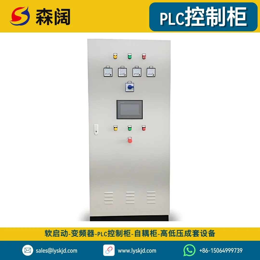
In real engineering, PLCs rarely “fight alone.” They typically serve as upper-level controllers, directing VFDs, soft starters, and other devices:
7.1 PLC + VFD
The PLC sends speed commands to the VFD Control Cabinet through analog signals (0-10V/4-20mA) or communication (Modbus/Profinet), and the VFD adjusts motor speed accordingly. Meanwhile, the PLC reads the VFD’s operating current and fault codes for closed-loop control and interlock protection.
Typical application: In a constant pressure water supply system, the PLC performs PID calculations based on pressure sensor feedback and outputs frequency commands to the VFD to maintain constant water pressure. For detailed principles, see How VFDs Achieve Constant Pressure Water Supply: Principles and Practice.
7.2 PLC + Soft Starter
For high-power motors that don’t need speed regulation but need smooth starting, the PLC controls the start/stop of the Online Soft Starter and receives its running/fault status signals. For soft starter selection methods, see Complete Soft Starter Selection Guide.
7.3 PLC + Distribution Cabinet
The PLC control cabinet itself requires a stable power supply, typically provided by Low-Voltage Distribution Cabinets or XL-21 Distribution Cabinets. The three form a complete “distribution — control — drive” hierarchy, which is the standard architecture of industrial electrical systems.
VIII. PLC Control Cabinet Selection Points
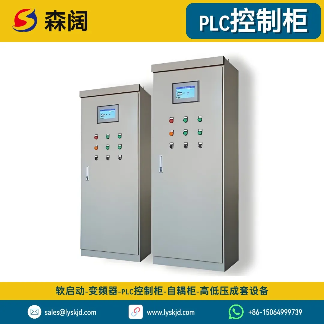
If you’re considering purchasing a PLC control cabinet, focus on the following:
8.1 I/O Points — Leave Sufficient Margin
Count all digital input/output and analog input/output points on site, and reserve 15%~20% expansion margin. Production lines may add inspection stations or actuators later; without margin, you’d have to replace the CPU or add racks, which costs more.
8.2 CPU Performance — Match the Process
Simple logic can use a small CPU; when PID closed-loop, high-speed counting, or motion control is involved, a mid-to-high-end CPU is needed. Don’t blindly pursue high performance — enough is good.
8.3 Communication Needs — Integration-Oriented
Clarify whether you need to connect to SCADA/MES systems, and whether you need to network with VFDs/instruments. Confirm communication protocols in advance to avoid “can’t talk to each other” later.
8.4 Protection Grade — Depends on Environment
IP20 is sufficient for clean control rooms; IP54 for dusty workshop environments; IP65 and above for outdoor or wash-down environments. Our OMNIMECH Series PLC Control Cabinet offers IP54/IP65 and other protection grades.
8.5 Brand and Ecosystem — Consider Maintenance
When choosing a PLC brand, consider the company’s existing equipment system (same brand facilitates spare parts sharing and personnel maintenance), local technical support capabilities, and ease of use of programming software. Mainstream brands include Siemens, Mitsubishi, Schneider, Omron, and domestic brands such as Inovance and Xinje.
IX. The Future of PLC: From “Island” to “Cloud”

With the advancement of Industry 4.0 and smart manufacturing, PLCs themselves are evolving:
9.1 Enhanced Edge Computing
New-generation PLCs have built-in web servers and database interfaces, enabling local data preprocessing to reduce reliance on the cloud and lower latency.
9.2 Deep Integration with IT Systems
Traditional PLCs were products of the OT (Operational Technology) world. Now they’re connecting with the IT world’s ERP, MES, and cloud platforms through protocols like OPC UA and MQTT, achieving “IT-OT convergence.”
9.3 More Open Programming
Structured text based on IEC 61131-3 is becoming increasingly popular. Some manufacturers also support Python and C programming, lowering the barrier for IT talent to enter the industrial field.
9.4 Safety and Cybersecurity
In the past, PLCs mostly ran in closed intranets. Now that they’re networked, they face cyber attack risks. Functional safety (SIL) and industrial cybersecurity have become new dimensions in PLC selection.
X. Conclusion
The PLC control cabinet is the “brain” of industrial automation. With reliable hardware, flexible software, and rich I/O, it turns complex process flows into lines of executable logic. From automotive production lines to sewage treatment plants, from central air conditioning to power monitoring, PLCs are everywhere, guarding the operation of modern industry.
If you’re planning an automation project, welcome to learn about our OMNIMECH Series PLC Control Cabinet — supporting multi-brand PLC integration including Siemens, Mitsubishi, and Schneider, providing full-process customized services from requirement research, program writing to on-site commissioning. We can also provide supporting equipment such as VFD Control Cabinets, Low-Voltage Distribution Cabinets, and Online Soft Starters to build a complete industrial automation solution.
📖 Further Reading
- Want to learn about motor speed control? Read Complete VFD Selection Guide
- Want to learn about motor start protection? Read Complete Soft Starter Selection Guide
- Want to learn about distribution system design? Read Industrial Low-Voltage Distribution Cabinet Selection Guide
- Want to learn about smart distribution trends? Read Application and Development of Smart Power Distribution Systems in Industrial Fields
Choosing the right PLC means installing a smart and reliable brain for your industrial system. We hope this article helps you build a complete understanding of PLC control systems.